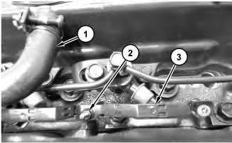
2. Use a deep socket to remove engine oil pressure sensor (1) from cylinder block (3).
i05243671
Installation Procedure
1. Install engine oil pressure sensor (1) in the reverse order of removal.
a. Use a deep socket to install engine oil pressure sensor (1) to the cylinder block. Tighten the engine oil pressure sensor to a torque of 15 to 19 N·m (134 to 169 lb in).
b. If necessary, replace engine oil pressure sensor (1) with new.
Copyright 1993 - 2024 Caterpillar Inc. All Rights Reserved.
Network For SIS Licensees. Tue Feb 27 19:13:57 UTC+0530 2024
This is the sample of the manual
Click on the download link for complete Manual
Product: MINI HYD EXCAVATOR
Model: 305E2 CR MINI HYD EXCAVATOR DJX
Configuration: 305E2 CR Mini Hydraulic Excavator DJX00001-UP (MACHINE) POWERED BY C2.4 Engine
Disassembly and Assembly
C1.7, C1.8 and C2.4 Tier 4 Interim and EU Stage 3A Engines for Caterpillar Built Machines
Media Number -UENR0128-12
Publication Date -01/08/2015
Date Updated -02/10/2019
Coolant Temperature Sensor - Remove and Install
SMCS - 1906-010
Removal Procedure
NOTICE
Keep all parts clean from contaminants.
Contaminants may cause rapid wear and shortened component life.
i05243665
NOTICE
Care must be taken to ensure that fluids are contained during performance of inspection, maintenance, testing, adjusting and repair of the product. Be prepared to collect the fluid with suitable containers before opening any compartment or disassembling any component containing fluids.
Dispose of all fluids according to local regulations and mandates.
1. Drain the coolant from the cooling system to a level below the coolant temperature sensor. Refer to Operation and Maintenance Manual, "Cooling System Coolant - Change" for the correct draining procedure.
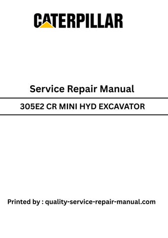
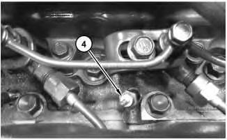
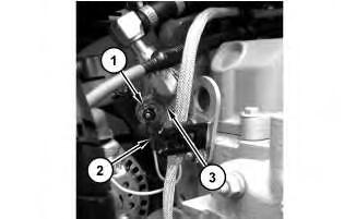
2. Disconnect harness assembly (2) from coolant temperature sensor (1).
3. Use a deep socket in order to remove coolant temperature sensor (1) from water temperature regulator (3).
Installation Procedure
1. Install coolant temperature sensor (1) in the reverse order of removal.
a. Use caution when tighten down harness assembly (2).
Copyright 1993 - 2024 Caterpillar Inc. All Rights Reserved. Private Network For SIS Licensees.
Tue Feb 27 19:13:45 UTC+0530 2024
Product: MINI HYD EXCAVATOR
Model: 305E2 CR MINI HYD EXCAVATOR DJX
Configuration: 305E2 CR Mini Hydraulic Excavator DJX00001-UP (MACHINE) POWERED BY C2.4 Engine
Disassembly and Assembly
C1.7, C1.8 and C2.4 Tier 4 Interim and EU Stage 3A Engines for Caterpillar Built Machines
Media Number -UENR0128-12 Publication Date -01/08/2015
Bearing Clearance - Check
SMCS - 1203-535; 1219-535
Measurement Procedure
Table 1
i05242994
198-9144
Plastic Gauge (Green)
to 0.076 mm (0.001 to 0.003 inch)
Plastic Gauge (Red) 0.051 to 0.152 mm (0.002 to 0.006 inch)
Plastic Gauge (Blue) 0.102 to 0.229 mm (0.004 to 0.009 inch)
Plastic Gauge (Yellow)
198-9145
0.230 to 0.510 mm (0.009 to 0.020 inch)
Note: Refer to Specification UENR0995 "Engine Design" for non-specified engine Torque Values.
Note: Plastic gauge may not be necessary when the engine is in the chassis.
Keep all parts clean from contaminants.
Contaminants may cause rapid wear and shortened component life.
Note: Caterpillar does not recommend the checking of the actual bearing clearances particularly on small engines. The checking can result in the possibility of obtaining inaccurate information and the possibility of damaging the bearing or the journal surfaces. Each Caterpillar engine bearing is quality checked for specific wall thickness.
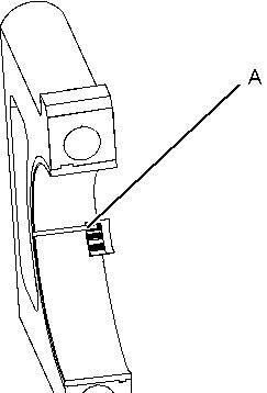
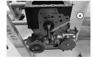
Note: The measurements should be within specifications and the correct bearings should be used. If the crankshaft journals and the bores for the block and the rods were measured during disassembly, no further checks are necessary. However, if the technician still wants to measure the bearing clearances, Tooling (A) is an acceptable method. Tooling (A) is less accurate on journals with small diameters if clearances are less than 0.10 mm (0.004 inch).
NOTICE
Lead wire, shim stock or a dial bore gauge can damage the bearing surfaces.
The technician must be careful to use Tooling (A) correctly. The following points must be remembered:
• Ensure that the backs of the bearings and the bores are clean and dry.
• Ensure that the bearing locking tabs are properly seated in the tab grooves.
• The crankshaft must be free of oil at the contact points of Tooling (A).
1. Put a piece of Tooling (A) on the crown of the bearing that is in the cap.
Note: Do not allow Tooling (A) to extend over the edge of the bearing.
2. Use the correct torque-turn specifications in order to install the bearing cap. Do not use an impact wrench. Be careful not to dislodge the bearing when the cap is installed.
Note: Do not turn the crankshaft when Tooling (A) is installed.
3. Carefully remove the cap, but do not remove Tooling (A). Measure the width of Tooling (A) while Tooling (A) is in the bearing cap or on the crankshaft journal. Refer to Illustration 1.
Illustration 1 g01152855
Typical Example
4. Remove all of Tooling (A) before you install the bearing cap.
Note: When Tooling (A) is used, the readings can sometimes be unclear. For example, all parts of Tooling (A) are not the same width. Measure the major width in order to ensure that the parts are within the specification range. Refer to Specifications Manual, "Connecting Rod Bearing Journal" and Specifications Manual, "Main Bearing Journal" for the correct clearances. Copyright 1993 - 2024 Caterpillar Inc. All Rights Reserved. Private Network For SIS Licensees. Tue Feb 27 19:13:33 UTC+0530 2024
Product: MINI HYD EXCAVATOR
Model: 305E2 CR MINI HYD EXCAVATOR DJX
Configuration: 305E2 CR Mini Hydraulic Excavator DJX00001-UP (MACHINE) POWERED BY C2.4 Engine
Disassembly and Assembly
C1.7, C1.8 and C2.4 Tier 4 Interim and EU Stage 3A Engines for Caterpillar Built Machines
Media Number -UENR0128-12
Publication Date -01/08/2015 Date Updated -02/10/2019
Crankshaft Gear - Remove and Install
SMCS - 1204-010-GE
Removal Procedure
Table 1
Required Tools
Tool Part Number
Part Description Qty
A 1P-2321 Puller Assembly 1
Start By:
a. Remove the idler gear.
NOTICE
Keep all parts clean from contaminants.
Contaminants may cause rapid wear and shortened component life.
i05243662
Illustration 1
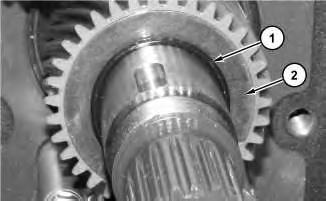
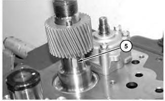
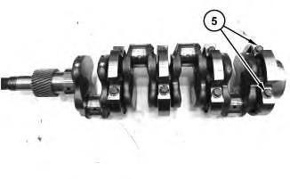
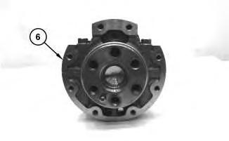
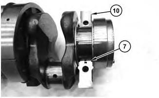
1. Remove o-ring (1) and collar (2).
Illustration 2
g02838697
Illustration 3
g02838698
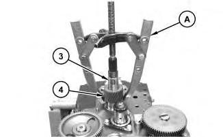
2. Use Tooling (A) in order to remove crankshaft gear (3) from crankshaft (4).
3. If necessary, remove key (5) from crankshaft (4).
Note: Do not remove the key from the crankshaft unless the key is damaged.
g02838617
Installation Procedure NOTICE
Keep all parts clean from contaminants.
Contaminants may cause rapid wear and shortened component life.
1. Ensure that all components are clean and free from wear and damage. If necessary, replace any components that are worn or damaged.
2. Install crankshaft gear (2) in the reverse order of the removal.
Note: The crankshaft gear (2) taper needs to face toward the cylinder block when installed. Copyright 1993 - 2024 Caterpillar Inc.
Product: MINI HYD EXCAVATOR
Model: 305E2 CR MINI HYD EXCAVATOR DJX
Configuration: 305E2 CR Mini Hydraulic Excavator DJX00001-UP (MACHINE) POWERED BY C2.4 Engine
Disassembly and Assembly
C1.7, C1.8 and C2.4 Tier 4 Interim and EU Stage 3A Engines for Caterpillar Built Machines
Media Number -UENR0128-12
Publication Date -01/08/2015
Crankshaft Main Bearings - Install
SMCS - 1203-012
Installation Procedure
Table 1
Required Tools
Tool Part Number
Part Description Qty
B 387-1351 Crankshaft Bearing Driver -
C 129-1967 Multipurpose White Grease 1
NOTICE
Keep all parts clean from contaminants.
Date Updated -02/10/2019
i05243660
Contaminants may cause rapid wear and shortened component life.
Note: Install the main bearings dry when the clearance checks are made.
Note: Install the crankshaft main bearings upper and lower halves, with the bearing tabs fitting into the notch of the crankshaft main bearing cases.
1
Illustration 2
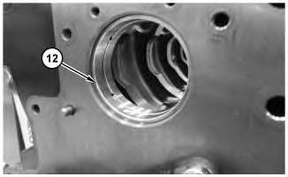
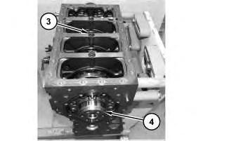
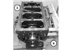
1. Use Tooling (B) and install crankshaft main bearing (12) into the front of the cylinder block. Install crankshaft main bearing (12) with the seam on the right or left side of the cylinder block.
Note: When the bearing clearance is checked, and the engine is in an upright position, or on the side. The crankshaft must be supported against the upper halves of the main bearings. Procedure is done in order to get a correct measurement with Tooling (B). If the crankshaft is not supported, the weight of the crankshaft will cause an incorrect reading. If the engine is not in an upright position or on the side, is not necessary to support the crankshaft.
Note: Refer to Guideline For Reusable Parts, SEBV0544, "Engine Bearings and Crankshafts" for complete details concerning the measurement of bearing clearances.
Illustration
g02715940
g02719957
3
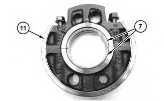
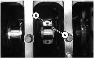
2. Apply Tooling (C) to crankshaft main bearings (7). Install crankshaft main bearings (7) in the upper and lower halves of crankshaft main bearing cases (11). Install three crankshaft main bearing cases (11).
Note: Be careful not to damage the bearings. Match each lower crankshaft main bearing case and the upper main bearing case in order to ensure installation in the original location. The three crankshaft main bearing cases are marked A-B-C with side markings FLYW and HEEL to face toward the flywheel. The rear crankshaft main bearing case to be installed with the bolt holes facing toward the rear of the cylinder block.
4
Illustration
g02715307
Illustration
g02715313
Illustration 5
3. Apply Tooling (C) to crankshaft main bearings (7). Install crankshaft main bearings (7) in the upper half of crankshaft main bearings case (10). Position crankshaft main bearings case (10) on the crankshaft.
4. Put Tooling (C) on thrust bearing (9) and install a new thrust bearing for the rear main bearing only. Install the new thrust bearing (9) with the flat surface against the crankshaft main bearing case (10). Apply Tooling (C) to crankshaft main bearings (7). Install crankshaft main bearings (7) in the lower half of crankshaft main bearings case (8). Position crankshaft main bearings case (8) on the crankshaft.
Illustration 6
g02715310
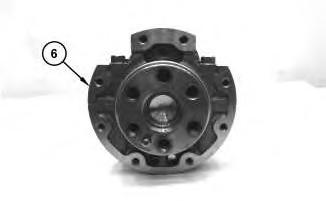
5. Install rear crankshaft main bearing case (6) onto the crankshaft.
Illustration 7
g02716456
6. Install bolts (5). Apply engine oil to threads and tighten bolts (5) to a torque of 46 to 50 N·m (34.0 to 37.0 lb ft).
Illustration 8
7. Install crankshaft (4). Install three bolts (3). Tighten bolts (3) to a torque of 69 to 73 N·m (51 to 54 lb ft).
Illustration 9
g02715938
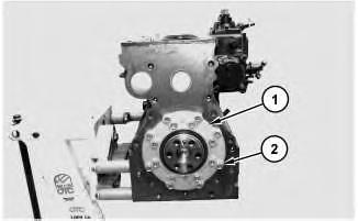
8. Position the gaskets and bearing case cover (1). Install bolts (2). Apply engine oil to threads and tighten bolts (2) to a torque of 24 to 27 N·m (18 to 20 lb ft).
End By:
a. Install the front housing.
b. Install the flywheel.
c. Install the piston and connecting rods.
Tue Feb 27 19:13:04 UTC+0530 2024
g02715301
Product: MINI HYD EXCAVATOR
Model: 305E2 CR MINI HYD EXCAVATOR DJX
Configuration: 305E2 CR Mini Hydraulic Excavator DJX00001-UP (MACHINE) POWERED BY C2.4 Engine
Disassembly and Assembly
C1.7, C1.8 and C2.4 Tier 4 Interim and EU Stage 3A Engines for Caterpillar Built Machines
Media Number -UENR0128-12
Publication Date -01/08/2015 Date Updated -02/10/2019
Crankshaft Main Bearings - Remove
SMCS - 1203-011
Removal Procedure
Table 1
Required Tools
Tool Part Number
Part Description Qty
A 387-1315 Crankshaft Bearing Driver 1
Start By:
a. Remove the piston and connecting rods.
b. Remove the flywheel.
c. Remove the front housing.
NOTICE
Keep all parts clean from contaminants.
Contaminants may cause rapid wear and shortened component life.
i05243655
Illustration 1
g02715938
1. Remove bolts (2), bearing case cover (1), and the gaskets.
Illustration 2
g02715301
2. Remove three bolts (3). Remove crankshaft (4).
Illustration 3
3. Remove bolts (5).
g02716456
Note: Be careful not to damage the bearings. Match each lower crankshaft main bearing case and the upper main bearing case in order to ensure installation in the original location.
The three crankshaft main bearing cases are marked A-B-C with side markings FLYW and HEEL to face toward the flywheel. The rear crankshaft main bearing case to be installed with the bolt holes facing toward the rear of the cylinder block.
4
4. Remove rear crankshaft main bearing case (6).
5
Illustration 6
Illustration
g02715310
Illustration
g02715314
g02715313
5. Remove lower half of crankshaft main bearing case (8), crankshaft main bearing (7), and thrust bearing (9).
6. Remove upper half of crankshaft main bearing case (10) and crankshaft main bearing (7).
7
7. Remove three crankshaft main bearing cases (11). Remove crankshaft main bearing (7) from the upper and lower halves of crankshaft main bearing case (11).
8
9
Illustration
g02715307
Illustration
g02715940
Illustration
g02715315
8. Remove crankshaft main bearing (12) from the front of the cylinder block with Tooling (A).
Note: Check the condition of the crankshaft main bearings. Refer to the Guideline For Reusable Parts, SEBF8009, "Main and Connecting Rod Bearings" or refer to the Guideline For Reusable Parts, SEBV0544, "Engine Bearings and Crankshafts". Copyright 1993 - 2024 Caterpillar Inc. All Rights Reserved. Private Network For SIS Licensees.
Product: MINI HYD EXCAVATOR
Model: 305E2 CR MINI HYD EXCAVATOR DJX
Configuration: 305E2 CR Mini Hydraulic Excavator DJX00001-UP (MACHINE) POWERED BY C2.4 Engine
Disassembly and Assembly
C1.7, C1.8 and C2.4 Tier 4 Interim and EU Stage 3A Engines for Caterpillar Built Machines
Media Number -UENR0128-12
Publication Date -01/08/2015 Date Updated -02/10/2019
Connecting Rod Bearings - Install
SMCS - 1219-012
Installation Procedure
NOTICE
Keep all parts clean from contaminants.
Contaminants may cause rapid wear and shortened component life.
i05399036
NOTICE
Discard all used Connecting Rod fasteners.
1. Ensure that the bearing shells are clean and free from wear and damage. If necessary, replace the bearing shells.
1
2. Install upper bearing shell (6) into connecting rod (5) . Ensure that the locating tab for the upper bearing shell is correctly seated in the slot in connecting rod (5) .
Note: The ends of the upper bearing shell must be centered in the connecting rod. The ends of the upper bearing shell are to be positioned equally in relation to the mating faces of the connecting rod.
3. Lubricate upper bearing shell (6) with clean engine oil.
2
4. Carefully pull connecting rod (5) against the crankshaft.
5. Clean connecting rod cap (4) . Install the lower bearing shell into connecting rod cap (4) . Ensure that the locating tab for the lower bearing shell is correctly seated in the slot in connecting rod cap (4) .
6. Lubricate the crankshaft and lubricate the lower bearing shell with clean engine oil.
7. Install connecting rod cap (4) to the connecting rod.
Note: Ensure that etched Number on connecting rod cap (4) matches etched Number on the connecting rod. Ensure the correct orientation of the connecting rod cap. The locating tab for the upper bearing shell and the lower bearing shell should be on the same side.
Illustration
g02720402
Illustration
g02720401
This is the sample of the manual
Click on the download link for complete Manual
8. Install new bolts (3) to the connecting rod. Apply engine oil to the threads and tighten the bolts evenly to a torque of 41 to 46 N·m (30 to 34 lb ft).
3
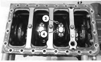
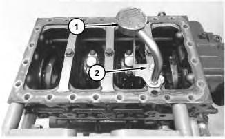
9. Position engine oil screen (1) and install the O-ring seal and bolt (2) .
10. Repeat Step 2 through Step 8 for the remaining connecting rod bearings.
Note: If all connecting rod bearings require replacement, the procedure can be carried out on two cylinders at the same time. The procedure can be carried out on the following pairs of cylinders. 1 with 4 and 2 with 3. Ensure that both pairs of the connecting rod bearings are installed before changing from one pair of cylinders to another pair of cylinders. Refer to Disassembly and Assembly, "Connecting Rod Bearings - Install" for the correct procedure.