Product: MINI HYD EXCAVATOR
Model: 305E2 CR MINI HYD EXCAVATOR R5C
Configuration: 305E2CR Mini Hydraulic Excavator R5C00001-UP (MACHINE) POWERED BY C2.4 Engine
Disassembly and Assembly
303.5E2, 304E2, 305E2 and 305.5E2 Mini Excavator Machine Systems
i06738351
Blade - Remove and Install
SMCS - 6060-010
Removal Procedure
Table 1
1
2
Illustration
g01226701
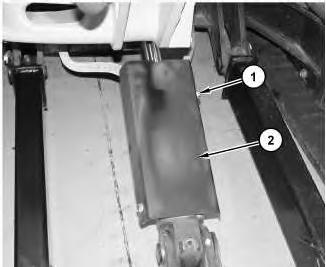
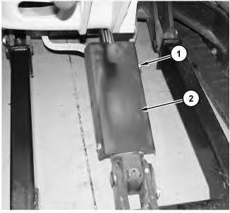
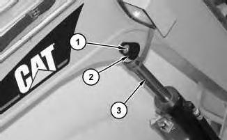
1. Remove bolts (1) and cover (2).
Illustration
g01226720
3
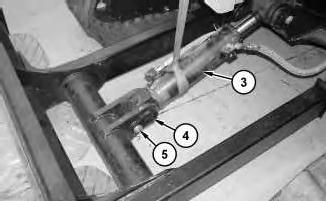
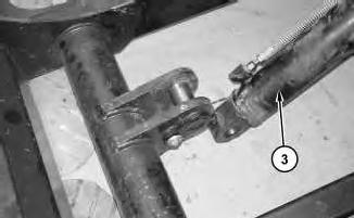
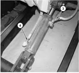
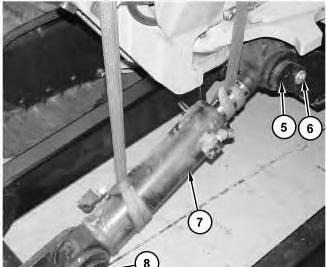
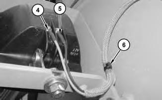
2. Attach a suitable lifting device to blade cylinder (3). The weight of blade cylinder (3) is approximately 18.1436 kg (40 lb). Remove bolt (5) and pin assembly (4). Lower the head end of blade cylinder (3) to the ground. Install pin assembly (4) and bolt (5).
4
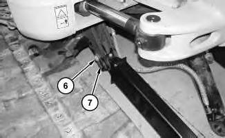
Illustration 5
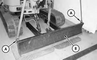
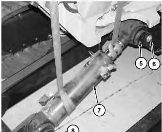
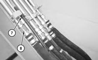
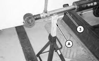
3. Attach Tooling (A) and a suitable lifting device to blade (8). The weight of blade (8) is approximately 192 kg (425 lb). Remove bolt (6) and pin assembly (7). Repeat for the other side.
Illustration
g01226721
Illustration
g01226749
g01226731
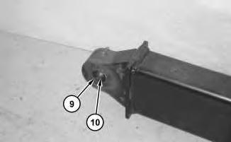
Illustration 6 g01226763
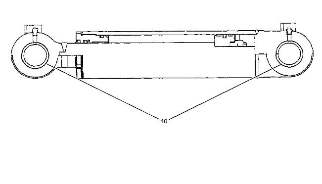
4. Remove lip seals (9). Use Tooling (B) to remove bushing (10). Repeat for the other side.
Installation Procedure
Table 2 Required Tools Tool Part Number Part Description Qty
A 189-0410 Shackle As 2
B 1P-0520 Driver Gp 1
Illustration 7 g01226763
1. Use Tooling (B) to install bushing (10). Repeat for the other side. Install lip seals (9).
Illustration 8
Illustration 9
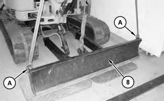
2. Attach Tooling (A) and a suitable lifting device to blade (8). The weight of blade (8) is approximately 192 kg (425 lb). Install pin assembly (7). Install bolt (6). Repeat for the other side.
Illustration 10
g01226749
g01226731
g01226721
This is the sample of the manual
Click on the download link for complete Manual
11
3. Remove bolt (5) and pin assembly (4). Attach a suitable lifting device to blade cylinder (3). The weight of blade cylinder (3) is approximately 18 kg (40 lb). Raise the head end of blade cylinder (3) into position. Install pin assembly (4) and bolt (5).
12
4. Install cover (2) and bolts (1). Copyright 1993 - 2020 Caterpillar Inc. All Rights Reserved. Private Network For SIS Licensees. Mon Nov 23 10:38:29 UTC+0530 2020
Illustration
g01226720
Illustration
g01226701
Product: MINI HYD EXCAVATOR
Model: 305E2 CR MINI HYD EXCAVATOR R5C
Configuration: 305E2CR Mini Hydraulic Excavator R5C00001-UP (MACHINE) POWERED BY C2.4 Engine
Disassembly and Assembly
303.5E2, 304E2, 305E2 and 305.5E2 Mini Excavator Machine Systems Media Number -M0074050-00
Blade Cylinder - Remove and Install
SMCS - 7562-010-BG
Removal Procedure
Start By:
a. Release the hydraulic system pressure.
i06732854
Cylinders equipped with lock valves can remain pressurized for very long periods of time, even with the hoses removed.
Failure to relieve pressure before removing a lock valve or disassembling a cylinder can result in personal injury or death.
Ensure all pressure is relieved before removing a lock valve or disassembling a cylinder.
Note: Put identification marks on all lines, on all hoses, on all wires, and on all tubes for installation purposes. Plug all lines, hoses, and tubes to prevent fluid loss and to keep contaminants from entering the system.
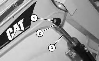
Illustration 1
1. Remove bolts (1) and cover (2).
2
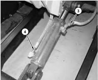
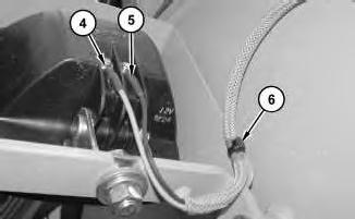
2. Disconnect hose assemblies (3) and (4).
g01226701
Illustration
g01226702
3
3. Attach a suitable lifting device to blade cylinder (7). The weight of blade cylinder (7) is approximately 34 kg (75 lb). Remove bolt (6) and pin assembly (5). Remove bolt (9) and pin assembly (8). Remove blade cylinder (7).
Disassembly and Assembly Information
When you are using hydraulic cylinders and puller studs, always ensure that the rated capacity of the puller stud meets or exceeds the rated capacity of the hydraulic cylinder. If the puller stud does not meet or
exceed the rated capacity of the hydraulic cylinder, a sudden failure of the puller stud could occur. The sudden failure of the puller stud could result in personal injury or death.
Cylinders equipped with lock valves can remain pressurized for very long periods of time, even with the hoses removed.
Failure to relieve pressure before removing a lock valve or disassembling a cylinder can result in personal injury or death.
Ensure all pressure is relieved before removing a lock valve or disassembling a cylinder.
Note: Tooling (A) is used for the installation of bearings (10) at the rod end and the head end of the blade cylinder. Tooling (B) is used for the removal of bearings (10) at the rod end and the head end of the blade cylinder.
Illustration 4
Installation Procedure
Illustration 5
1. Attach a suitable lifting device to blade cylinder (7). The weight of blade cylinder (7) is approximately 34 kg (75 lb). Install blade cylinder (7). Install pin assembly (5) and bolt (6). Install pin assembly (8) and bolt (9).
6 g01226702
2. Connect hose assemblies (3) and (4).
Illustration
Illustration 7
3. Install cover (2) and bolts (1).
Copyright 1993 - 2020 Caterpillar Inc. All Rights Reserved. Private Network For SIS Licensees.
Mon Nov 23 10:38:13 UTC+0530 2020
Product: MINI HYD EXCAVATOR
Model: 305E2 CR MINI HYD EXCAVATOR R5C
Configuration: 305E2CR Mini Hydraulic Excavator R5C00001-UP (MACHINE) POWERED BY C2.4 Engine
Disassembly and Assembly
303.5E2, 304E2, 305E2 and 305.5E2 Mini Excavator Machine Systems Media
i04777959
Blower Motor (Air Conditioner, Heater) - Remove and Install
SMCS - 7304-010-BW; 7309-010-BW; 7320-010-BW
Removal Procedure
Start By:
a. Remove the heating and air conditioning unit.
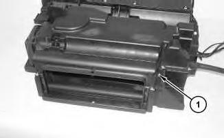
Illustration 1 g01226046
1. Remove screws (1).
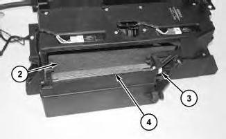
Illustration 2
2. Remove cab air filter (2). Remove cap (3) and louver (4).
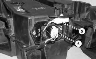
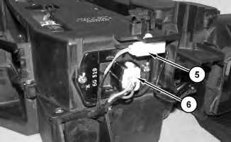
Illustration 3
g01226033
3. Disconnect harness assemblies (5) and (6).
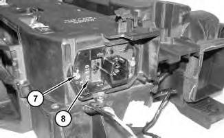
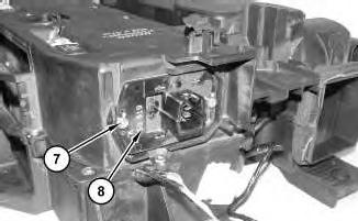
Illustration 4
g01225163
4. Remove screws (7) and switch assembly (8).
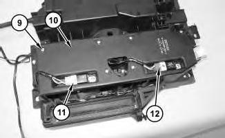
g01226042
Illustration 5
5. Disconnect relay assemblies (11) and (12). Remove screws (9) and cover (10).
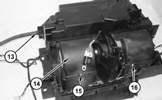
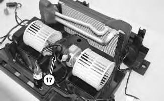
Illustration 6
6. Remove hose (13). Remove screws (15) and (16). Remove cover (14).
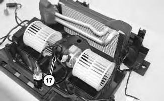
Illustration 7
g01226099
g01226109
g01226111
7. Remove blower motor (17).
Installation Procedure
Illustration 8
1. Install blower motor (17).
Illustration 9
2. Install cover (14). Install screws (15) and (16). Install hose (13).
g01226111
g01226109
Illustration 10
3. Install cover (10) and screws (9). Connect relay assemblies (11) and (12).
Illustration 11
4. Install switch assembly (8) and screws (7).
Illustration 12
5. Connect harness assemblies (5) and (6).
g01226099
g01225163
g01226033
13
Illustration 14
7. Install screws (1).
End By: a. Install the heating and air conditioning unit.
Mon Nov 23 10:45:38 UTC+0530 2020
Network For SIS
Illustration
g01226042
6. Install louver (4) and cap (3). Install cab air filter (2).
g01226046
Product: MINI HYD EXCAVATOR
Model: 305E2 CR MINI HYD EXCAVATOR R5C
Configuration: 305E2CR Mini Hydraulic Excavator R5C00001-UP (MACHINE) POWERED BY C2.4 Engine
Disassembly and Assembly
303.5E2, 304E2, 305E2 and 305.5E2 Mini Excavator Machine Systems Media
i06741160
Boom - Install
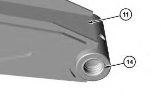
1. Use Tooling (C) to install bearings (14) into boom (11).
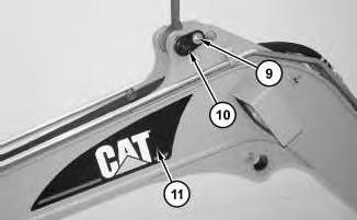
2. Install pin assembly (10) that is retained the head end of the stick cylinder. Install bolt (9). Attach a suitable lifting device to pin assembly (10). Pin assembly (10) will be used for the installation of boom assembly (11). The weight of boom assembly (11) is approximately 295 kg (650 lb).
Illustration 2
g01233290
Illustration 3
g01233293
Illustration 4
g01233291
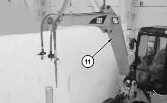
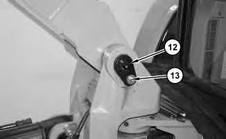
3. Install boom assembly (11). Install pin assembly (12) and bolt (13).
Connect hose assemblies (8). Install clip (7).
6
5. Connect harness assemblies (4) and (5). Install cable straps (6).
Illustration 5
g01233285
4.
Illustration
g01233224
Illustration 7
Illustration 8
6. Attach a suitable lifting device to the rod end of boom cylinder (3). The weight of the rod end of boom cylinder (3) is approximately 25 kg (55 lb). Raise the rod end of boom cylinder off Tooling (A) and into position. Install pin assembly (2) and bolt (1).
End By:
a. Install the stick.
b. Install the stick cylinder. Copyright 1993 - 2020 Caterpillar Inc. All Rights Reserved. Private Network For SIS Licensees.
Product: MINI HYD EXCAVATOR
Model: 305E2 CR MINI HYD EXCAVATOR R5C
Configuration: 305E2CR Mini Hydraulic Excavator R5C00001-UP (MACHINE) POWERED BY C2.4 Engine
Disassembly and Assembly
303.5E2, 304E2, 305E2 and 305.5E2 Mini Excavator Machine Systems
i06740977
Boom - Remove
Removal Procedure
Table 1 Required Tools
Start By:
a. Remove the stick cylinder.
b. Remove the stick.
When you are using hydraulic cylinders and puller studs, always ensure that the rated capacity of the puller stud meets or exceeds the rated capacity of the hydraulic cylinder. If the puller stud does not meet or exceed the rated capacity of the hydraulic cylinder, a sudden failure of the puller stud could occur. The sudden failure of the puller stud could result in personal injury or death.
Note: Put identification marks on all lines, on all hoses, on all wires, and on all tubes for installation purposes. Plug all lines, hoses, and tubes to prevent fluid loss and to keep contaminants from entering the system.
1
2
1. Attach a suitable lifting device to the rod end of boom cylinder (3). The weight of the rod end of boom cylinder (3) is approximately 25 kg (55 lb). Remove bolt (1) and pin assembly (2). Lower the rod end of boom cylinder (3) onto Tooling (A).
Illustration
g01233220
Illustration
g01233222
This is the sample of the manual
Click on the download link for complete Manual
Illustration 3
g01233224
2. Disconnect harness assemblies (4) and (5). Remove cable straps (6).
Illustration 4
g01233285
3. Remove clip (7). Disconnect hose assemblies (8).
Illustration 5
g01233290