

Product: MINI HYD EXCAVATOR
Model: 305C CR MINI HYD EXCAVATOR HWJ
Configuration: 305 C CR Mini Hydraulic Excavator HWJ00001-UP (MACHINE) POWERED BY S4Q2T Engine
Disassembly and Assembly
S4Q2-T Engine
Media Number -KENR6788-04
Publication Date -01/09/2013
Air Inlet and Exhaust System - Inspect
SMCS - 1050-040
Measuring exhaust manifold distortion
Date Updated -12/09/2013
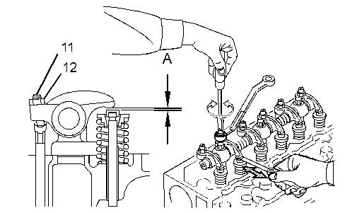
i04020373
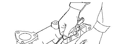

Illustration 1 g02239554
1. Check the flange for crack.
2. Check the flange surface for distortion. If the distortion exceeds the standard, retouch the surface.
Table 1 Item Standard
Exhaust manifold distortion Less than 0.150 mm (0.0059 inch)
Copyright 1993 - 2020 Caterpillar Inc. All Rights Reserved. Private Network For SIS Licensees. Fri Nov 6 12:02:06 UTC+0530 2020
Product: MINI HYD EXCAVATOR
Model: 305C CR MINI HYD EXCAVATOR HWJ
Configuration: 305 C CR Mini Hydraulic Excavator HWJ00001-UP (MACHINE) POWERED BY S4Q2T Engine
Disassembly and Assembly
S4Q2-T Engine
Media Number -KENR6788-04 Publication Date -01/09/2013 Date Updated -12/09/2013
Air Inlet and Exhaust System - Install
SMCS - 1050-012
Installing inlet and exhaust system
i04077149
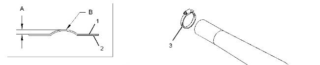
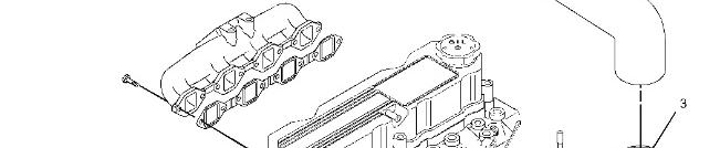
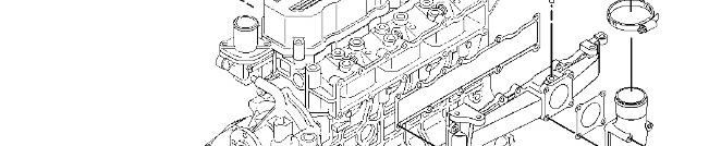

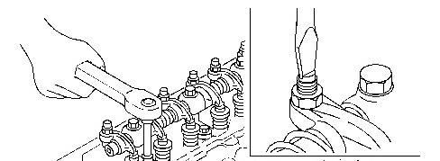
Illustration 1 g02285694
1. Replace all the inlet and exhaust system gaskets.
2. Exhaust gasket installing at exhaust manifold side (1) .
3. Exhaust gasket installing at cylinder head side (2) .
4. Tighten the clamps (3) to 7 ± 1 N·m (62 ± 9 lb in).
5. Dimension for (A) 1.0 mm (0.04 inch).
6. Radius for (B) 5.0 mm (0.20 inch).
Product: MINI HYD EXCAVATOR
Model: 305C CR MINI HYD EXCAVATOR HWJ
Configuration: 305 C CR Mini Hydraulic Excavator HWJ00001-UP (MACHINE) POWERED BY S4Q2T Engine
Disassembly and Assembly
S4Q2-T Engine
Media Number -KENR6788-04
Publication Date -01/09/2013 Date Updated -12/09/2013
Air Inlet and Exhaust System - Remove
SMCS - 1050-011
Removing inlet and exhaust system
i04077129
This is the sample of the manual
Click on the download link for complete Manual

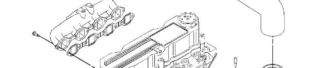
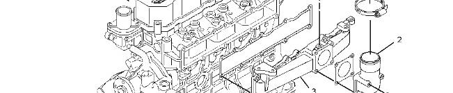

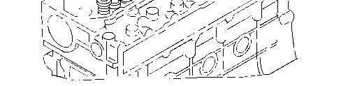
Illustration 1
Removing sequence
Air hose
Air inlet elbow
Inlet manifold
Exhaust manifold
Copyright 1993 - 2020 Caterpillar Inc. All Rights Reserved. Private Network For SIS Licensees. Fri Nov 6 12:01:51 UTC+0530 2020
Product: MINI HYD EXCAVATOR
Model: 305C CR MINI HYD EXCAVATOR HWJ
Configuration: 305 C CR Mini Hydraulic Excavator HWJ00001-UP (MACHINE) POWERED BY S4Q2T Engine
Disassembly and Assembly
S4Q2-T Engine
Media Number -KENR6788-04 Publication Date -01/09/2013 Date Updated -12/09/2013
i04020371
Cooling System - Disassemble/Inspect/Assemble
SMCS - 1350-017; 1350-040
Disassembling, inspecting, and reassembling water pump
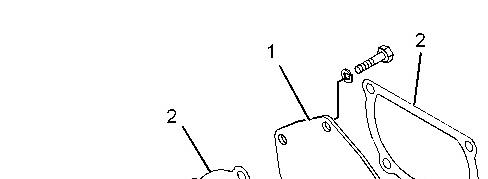
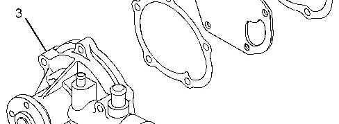

Illustration 1 g02239513
Disassembling sequence
(1) Water pump cover
(2) Gasket
(3) Water pump
Inspect the water pump cover (1) for crack, water leakage, and distortion. Replace both the gaskets (2) during assembly. Inspect the water pump (3) for crack, water leakage, damage, impeller, and shaft of rotation.
Inspecting water pump for smooth rotation
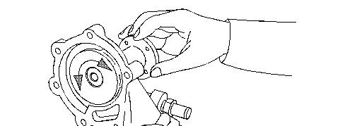

Illustration 2 g02239514
Check to make sure that the impeller and shaft of water pump rotate smoothly without noise and irregularities. If faulty, replace the water pump assembly.
Disassembling, inspecting, and reassembling thermostat
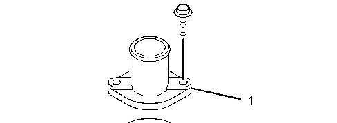
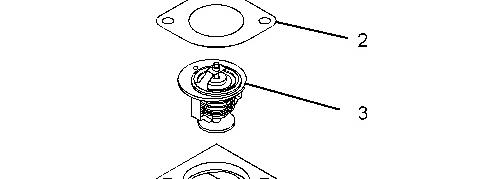

Illustration 3 g02239515
Disassembling sequence
(1) Thermostat cover
(2) Gasket
(3) Thermostat
(4) Thermostat case
Inspecting thermostat
Note: Be careful of burns or a fire when measuring temperature, as it involves a hightemperature and open flame.


Illustration 4 g02239516
To test the thermostat operation, immerse the thermostat in a container filled with water. Heat the water, while measuring the water temperature. Record the temperature at the conditions shown in the table below. If the temperatures are not within the standard range, replace the thermostat.
Note: Stir the water in the container with a stick to ensure uniform temperature distribution. Before installing the thermostat, be sure to check the valve opening temperature stamped on the thermostat valve side face.
Table 1
Item Standard
Temperature at which valve starts opening 75 to 78 °C (167 to 172 °F)
Temperature at which valve lift becomes 8.0 mm (0.31 inch) or more. 90 °C (194 °F)
Copyright 1993 - 2020 Caterpillar Inc.
Network For SIS Licensees. Fri Nov 6 12:01:23 UTC+0530 2020
Product: MINI HYD EXCAVATOR
Model: 305C CR MINI HYD EXCAVATOR HWJ
Configuration: 305 C CR Mini Hydraulic Excavator HWJ00001-UP (MACHINE) POWERED BY S4Q2T Engine
Disassembly and Assembly
S4Q2-T Engine
Media Number -KENR6788-04
Publication Date -01/09/2013 Date Updated -12/09/2013
Cooling System - Install
SMCS - 1350-012
Installation cooling system
i04023331
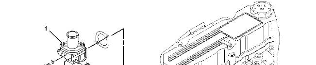
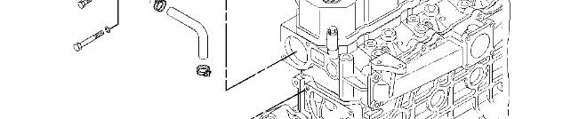

Illustration 1
1. Replace all the gaskets, O-rings, and rubber hoses.
2. Tighten the thermostat cover bolts (1) to 18 ± 2 N·m (159 ± 18 lb in).
3. Tighten the water pump bolts (2) to 10 ± 1 N·m (88 ± 9 lb in).
Copyright 1993 - 2020 Caterpillar Inc. All Rights Reserved. Private Network For SIS Licensees. Fri Nov 6 12:01:37 UTC+0530 2020
Product: MINI HYD EXCAVATOR
Model: 305C CR MINI HYD EXCAVATOR HWJ
Configuration: 305 C CR Mini Hydraulic Excavator HWJ00001-UP (MACHINE) POWERED BY S4Q2T Engine
Disassembly and Assembly
S4Q2-T Engine
Media Number -KENR6788-04
Publication Date -01/09/2013 Date Updated -12/09/2013
Cooling System - Remove
SMCS - 1350-011
Removing cooling system
i04037726
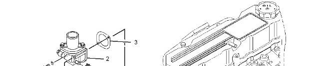
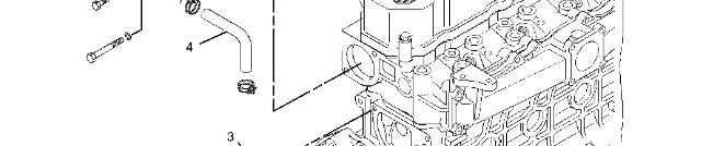

Illustration 1 g02239553
Removing sequence
(1) Water pump assembly
(2) Thermostat
Replace the gaskets (3) during installation.
Inspect the rubber hose (4) for cracked, distortion, and damage.
Inspect the thermostat (2) for crack and damage.
Inspect the water pump assembly (1) for crack, water leakage, and damage.
Copyright 1993 - 2020 Caterpillar Inc. All Rights Reserved. Private Network For SIS Licensees. Fri Nov 6 12:01:08 UTC+0530 2020
Product: MINI HYD EXCAVATOR
Model: 305C CR MINI HYD EXCAVATOR HWJ
Configuration: 305 C CR Mini Hydraulic Excavator HWJ00001-UP (MACHINE) POWERED BY S4Q2T Engine
Disassembly and Assembly
S4Q2-T Engine
Media Number -KENR6788-04 Publication Date -01/09/2013 Date Updated -12/09/2013
Cylinder Head and Valve Mechanism - Assemble
SMCS - 1100-016; 1102-016
Installing valve stem seal
i04020349
Note: Do not apply oil or liquid gasket to the inner side of stem seal that comes in contact with the valve guide.

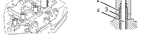
Illustration 1 g02237654 (1) Stem seal installer (P/N:32C91-10400)
(2) Valve stem seal
(3) Valve guide
(4) Valve
1. Apply engine oil to the lip of new valve stem seal.
2. Push the shoulder of the valve stem seal and fit the valve stem steal into the valve guide.
3. Insert the valve stem seal into the valve guide using the valve stem seal installer.
Installing valve and valve spring

Illustration 2 g02237675
1. Install the valve spring and retainer on the valve guide. Install the valve cotter using a valve spring pusher (5) .
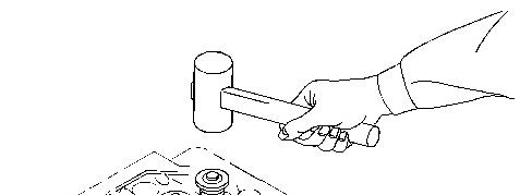

Illustration 3 g02237793
2. Tap the top of valve stem lightly several times with a soft hammer to make sure that the valve spring and valve cotter are properly installed and seated firmly.
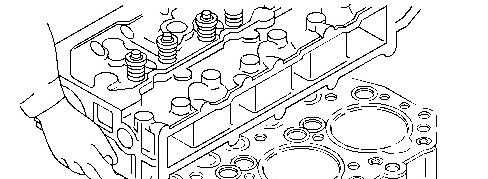
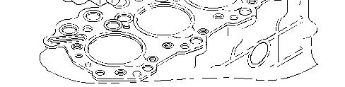
Installing cylinder head gasket
Note: Do not use liquid gasket.
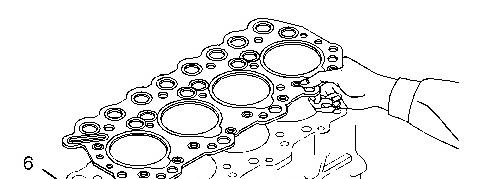

Illustration 4 g02237796
1. Wipe off oil, grease, and other stains from the cylinder head bottom surface and the crankcase upper surface with a shop towel.
2. Install the cylinder head gasket that has been coated with liquid gasket onto the crankcase with the dowel pin (6) and the hole in alignment.
Installing cylinder head assembly
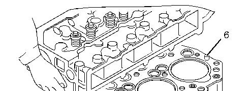
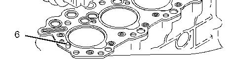
Illustration 5 g02237813
Install the cylinder head on the crankcase by aligning the cylinder head with the dowel pins (6) .
Note: Be careful not to displace the cylinder gasket when installing.
Tightening cylinder head bolts
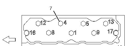
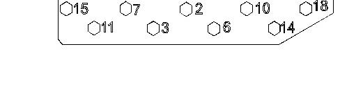
Illustration 6 g02237817
Tightening sequence of cylinder head bolts.
White arrow shows front of engine.
Tighten the cylinder head bolts (7) in the numerical sequence to 118 ± 5 N·m (87 ± 4 lb ft).
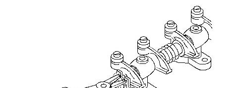
Reassembling rocker shaft assembly
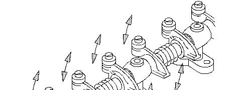

Illustration 7 g02237873 (8) Reassembling mark
1. Apply engine oil to the rocker shaft.
2. When reassembling, install the rocker shaft assembly in the original position.
Note: If the rocker shaft assembly is not installed in the original position, the clearance becomes different. The different may result in a defect such as wear increase.
3. After reassembling, make sure the rocker arm and oil pipe move freely.
Inserting push rod
1. Insert each push rod into hole in the cylinder head.
2. Make sure that the ball end of each push rod is placed correctly on the tappet cup.
Installing rocker shaft assembly
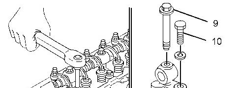
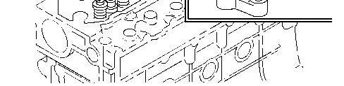
Illustration 8 g02237874
1. Install the valve caps to the valve heads.
2. Tighten the long bolts (9) of the rocker bracket to 15 ± 2 N·m (133 ± 18 lb in).
3. Tighten the short bolts (10) of the rocker bracket to 11.3 ± 1.5 N·m (100.0 ± 13.0 lb in)