Previous Screen
Product: MINI HYD EXCAVATOR
Model: 305.5 MINI HYD EXCAVATOR DCK
Configuration: 305.5 Mini Hydraulic Excavator DCK00001-UP (MACHINE) POWERED BY 4M40 Engine
Disassembly and Assembly 4M40 DIESEL ENGINE SHOP MANUAL
Shutdown SIS
Media Number -KENR5078-00 Publication Date -01/11/2007 Date Updated -01/12/2014
General
SMCS - 5051-012
Information Location
KENR50780012
This shop manual is published for the information and guidance of personnel responsible for maintenance of Mitsubishi 4M40 series diesel engine, and includes procedures for adjustment and maintenance services. We earnestly look forward to seeing that this manual is made full use of in order to perform correct services with no wastage.
Disassembly and Assembly information is located under General Service Information.
Copyright 1993 - 2020 Caterpillar Inc. All Rights Reserved. Private Network For SIS Licensees. Mon Oct 12 15:49:18 UTC+0530 2020
Previous Screen
Product: MINI HYD EXCAVATOR
Model: 305.5 MINI HYD EXCAVATOR DCK
Configuration: 305.5 Mini Hydraulic Excavator DCK00001-UP (MACHINE) POWERED BY 4M40 Engine
Disassembly and Assembly
305.5 and 306 Mini Hydraulic Excavators Machine Systems
i02336431
Blade - Remove and Install
SMCS - 6060-010
Removal Procedure Table 1
1. Position the blade on the ground. Rotate the machine to the side in order to gain access to the blade.
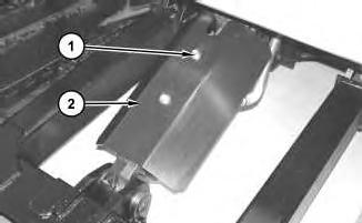
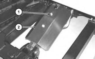
2. Remove bolts (1) and guard (2).
2
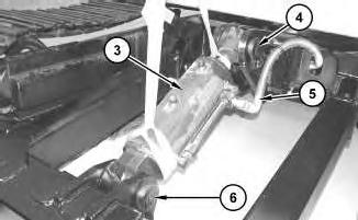
3. Attach a suitable lifting device to blade cylinder (3). The weight of blade cylinder (3) is approximately 36 kg (80 lb). Remove bolt (5) and pin assembly (4). Lower the rod end of blade cylinder (3) to the ground.
3
Illustration
g01166068
Illustration
g01166070
Illustration 4
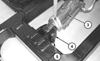
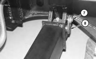
4. Install pin assembly (4) and install bolt (5) that was removed in the previous step. Attach Tooling (A) and a suitable lifting device to blade (6). The weight of blade (6) is approximately 227 kg (500 lb).
Remove bolt (7) and pin assembly (8). Repeat for the other side. Remove blade (6).
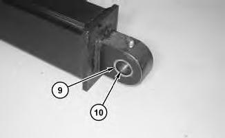
Illustration 5
5. Remove lip seals (9). Use Tooling (B) in order to remove bushing (10). Repeat for the other side.
Installation Procedure
1. Lower the temperature of bushing (10). Use Tooling (B) in order to install bushing (10) to a depth of 5.00 mm (0.1969 inch). Repeat for the other side. Use Tooling (B) in order to install lip seals (9).
Illustration 6
g01166080
Illustration 7
g01166070
Illustration 8
g01166073
2. Attach Tooling (A) and a suitable lifting device to blade (6). The weight of blade (6) is approximately 227 kg (500 lb).
Install blade (6). Install pin assembly (8) and bolt (7).
Illustration 9
3. Attach a suitable lifting device to the rod end of blade cylinder (3). The weight of blade cylinder (3) is approximately 36 kg (80 lb). Raise the rod end of blade cylinder (3) into position and install pin assembly (4) and bolt (5).
Illustration 10
4. Install guard (2) and bolts (1).
Copyright 1993 - 2020 Caterpillar Inc. All Rights Reserved. Private Network For SIS Licensees. Mon Oct 12 14:50:38 UTC+0530 2020
g01166068
g01166033
This is the sample of the manual
Click on the download link for complete Manual
Previous Screen
Product: MINI HYD EXCAVATOR
Model: 305.5 MINI HYD EXCAVATOR DCK
Configuration: 305.5 Mini Hydraulic Excavator DCK00001-UP (MACHINE) POWERED BY 4M40 Engine
Disassembly and Assembly
305.5 and 306 Mini Hydraulic Excavators Machine Systems
Blade Cylinder - Remove and Install
SMCS - 7562-010-BG
Removal Procedure
Start By:
a. Release the hydraulic system pressure. Refer to Disassembly and Assembly, "Hydraulic Sytem Pressure - Release".
Cylinders equipped with lock valves can remain pressurized for very long periods of time, even with the hoses removed.
Failure to relieve pressure before removing a lock valve or disassembling a cylinder can result in personal injury or death.
Ensure all pressure is relieved before removing a lock valve or disassembling a cylinder.
NOTICE
Care must be taken to ensure that fluids are contained during performance of inspection, maintenance, testing, adjusting, and repair of the product. Be prepared to collect the fluid with suitable containers
i02393831
before opening any compartment or disassembling any component containing fluids.
Refer to Special Publication, NENG2500, "Dealer Service Tool Catalog" for tools and supplies suitable to collect and contain fluids on Cat products.
Dispose of all fluids according to local regulations and mandates.
1. Position the blade on the ground. Rotate the machine to the side in order to gain access to the blade cylinder.
1
2. Remove bolts (1) and guard (2).
2
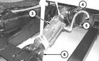
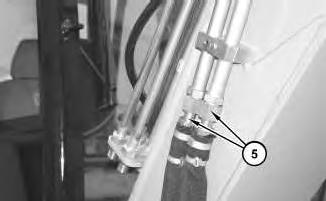
3. Attach a suitable lifting device to blade cylinder (3). The weight of blade cylinder (3) is approximately 68 kg (150 lb). Disconnect hose assemblies (5). Remove pin assemblies (4) and (6). Remove blade cylinder (3).
Illustration
g01166033
Illustration
g01166055
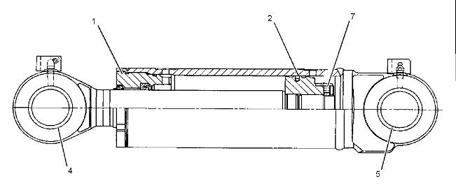
Disassembly and Assembly
Note: Tooling (A) is used for the removal and the installation of bearings (4) and (5). Tooling (B) is used for the removal and the installation of cylinder head (1).
(3) Torque for locknut ... 2210 N·m (1630 lb ft)
(2) Lubricate the sealing lip slightly with the lubricant that is being sealed.
(1) Torque for head ... 834 N·m (615 lb ft)
Installation Procedure
4
1. Attach a suitable lifting device to blade cylinder (3). The weight of blade cylinder (3) is approximately 68 kg (150 lb). Install blade cylinder (3). Install pin assemblies (4) and (6). Connect hose assemblies (5).
Illustration 5
2. Install guard (2) and bolts (1).
Illustration
g01166055
g01166033
Previous Screen
Product: MINI HYD EXCAVATOR
Model: 305.5 MINI HYD EXCAVATOR DCK
Configuration: 305.5 Mini Hydraulic Excavator DCK00001-UP (MACHINE) POWERED BY 4M40 Engine
Disassembly and Assembly
305.5 and 306 Mini Hydraulic Excavators Machine Systems
Blower Motor (Heater) - Remove and Install
SMCS - 7304-010-BW
Removal Procedure
Start By:
Shutdown SIS
a. Remove the cab heater. Refer to Disassembly and Assembly, "Cab Heater - Remove".
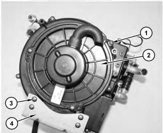
Illustration 1 g01162400
1. Remove bolts (3) and bracket (4). Remove bolts (1) and blower motor (2).
i02326982
Illustration 2
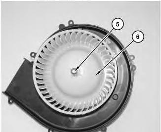
2. Remove clip (5) and cage (6).
Installation Procedure
g01162401
Illustration 3
1. Install cage (6) and install clip (5).
g01162401
Illustration 4
2. Install blower motor (2) and install bolts (1). Install bracket (4) and install bolts (3).
End By:
a. Install the cab heater. Refer to Disassembly and Assembly, "Cab Heater - Install".
Mon Oct 12 15:08:15 UTC+0530 2020
Previous Screen
Product: MINI HYD EXCAVATOR
Model: 305.5 MINI HYD EXCAVATOR DCK
Configuration: 305.5 Mini Hydraulic Excavator DCK00001-UP (MACHINE) POWERED BY 4M40 Engine
Disassembly and Assembly
305.5 and 306 Mini Hydraulic Excavators Machine Systems
Shutdown SIS
Boom - Install
SMCS - 6501-012
Installation Procedure Table 1
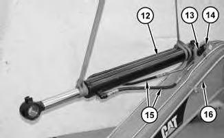
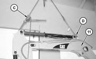
Illustration 1
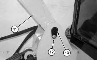
1. Attach a suitable lifting device to stick cylinder (12). The weight of stick cylinder (12) is approximately 68 kg (150 lb). Install stick cylinder (12).
i02335614
Install pin assembly (13) and bolt (14). Connect hose assemblies (15). Install hose assemblies (15) and tube assemblies (16), if necessary.
2
3
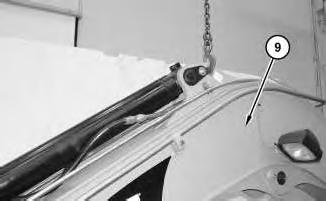
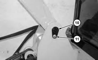
2. Attach a suitable lifting device to boom (9). The weight of boom (9) is approximately 363 kg (800 lb). Install boom (9). Install pin assembly (10) and bolt (11).
Illustration
g01165748
Illustration
g01165753
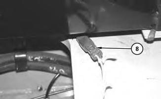
Illustration 4
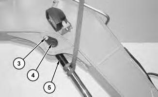
3. Install the cable straps. Connect harness assembly (8).
Illustration 5
4. Install panel (7) and bolts (6).
Illustration 6
5. Connect hose assemblies (5).
g01165744
g01165741
g01165740
Illustration 7 g01165738
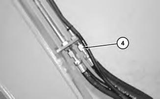
6. Connect hose assemblies (4).
Illustration 8
g01165735
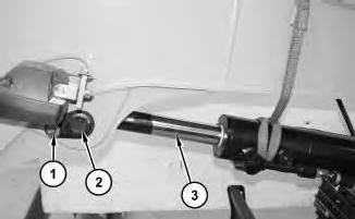
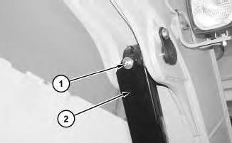
7. Attach a suitable lifting device to boom cylinder (3). The weight of boom cylinder (3) is approximately 36 kg (80 lb). Raise boom cylinder (3) into position. Install pin assembly (2) and install bolt (1) .
Illustration 9
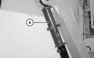
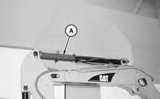
8. Install Tooling (A).
g01165729
Note: Tooling (A) will be used for the installation of the stick.
End By:
a. Install the stick. Refer to Disassembly and Assembly, "Stick - Install".
Previous Screen
Product: MINI HYD EXCAVATOR
Model: 305.5 MINI HYD EXCAVATOR DCK
Configuration: 305.5 Mini Hydraulic Excavator DCK00001-UP (MACHINE) POWERED BY 4M40 Engine
Disassembly and Assembly
305.5 and 306 Mini Hydraulic Excavators Machine Systems
Boom - Remove
SMCS - 6501-011
Removal Procedure
Start By:
a. Remove the stick. Refer to Disassembly and Assembly, "Stick - Remove".
Cylinders equipped with lock valves can remain pressurized for very long periods of time, even with the hoses removed.
Failure to relieve pressure before removing a lock valve or disassembling a cylinder can result in personal injury or death.
Ensure all pressure is relieved before removing a lock valve or disassembling a cylinder.
NOTICE
Care must be taken to ensure that fluids are contained during performance of inspection, maintenance, testing, adjusting, and repair of the product. Be prepared to collect the fluid with suitable containers
i02335473
before opening any compartment or disassembling any component containing fluids.
Refer to Special Publication, NENG2500, "Dealer Service Tool Catalog" for tools and supplies suitable to collect and contain fluids on Cat products.
Dispose of all fluids according to local regulations and mandates.
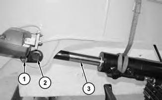
Illustration 1
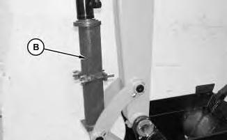
1. Remove Tooling (A). Position the boom on the ground.
Note: Tooling (A) was used in the removal of the stick.
2
2. Attach a suitable lifting device to boom cylinder (3). The weight of boom cylinder (3) is approximately 36 kg (80 lb). Remove bolt (1) and pin assembly (2). Lower boom cylinder (3) to the ground.
g01165729
Illustration
g01165735
3
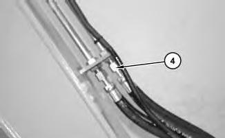
Illustration 4
Illustration 5
Illustration
g01165738
3. Disconnect hose assemblies (4).
g01165740
4. Disconnect hose assemblies (5).
g01165741
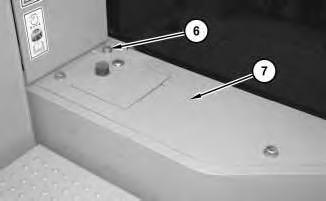
5. Remove bolts (6) and panel (7).
6
6. Disconnect harness assembly (8). Cut the cable straps.
7
Illustration 8
Illustration
g01165744
Illustration
g01165748
g01165753
7. Attach a suitable lifting device to boom (9). The weight of boom (9) is approximately 363 kg (800 lb). Remove bolt (11) and pin assembly (10). Remove boom (9).
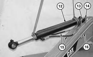
Illustration 9 g01165756
8. Attach a suitable lifting device to stick cylinder (12). The weight of stick cylinder (12) is approximately 68 kg (150 lb).
If necessary, remove hose assemblies (15) and tube assemblies (16). Disconnect hose assemblies (15). Remove bolt (14) and pin assembly (13). Remove stick cylinder (12). If necessary, remove hose assemblies (15) and tube assemblies (16). Copyright 1993 - 2020 Caterpillar Inc.
Rights Reserved.
Network For SIS Licensees. Mon Oct 12 14:57:34 UTC+0530 2020
Previous Screen
Product: MINI HYD EXCAVATOR
Model: 305.5 MINI HYD EXCAVATOR DCK
Configuration: 305.5 Mini Hydraulic Excavator DCK00001-UP (MACHINE) POWERED BY 4M40 Engine
Disassembly and Assembly
305.5 and 306 Mini Hydraulic Excavators Machine Systems
Boom Bearings and Seals - Remove and Install
SMCS - 6501-010-BD; 6501-010-SA
Removal Procedure
Table 1
Cylinders equipped with lock valves can remain pressurized for very long periods of time, even with the hoses removed.
Failure to relieve pressure before removing a lock valve or disassembling a cylinder can result in personal injury or death.
Ensure all pressure is relieved before removing a lock valve or disassembling a cylinder.
NOTICE
Care must be taken to ensure that fluids are contained during performance of inspection, maintenance, testing, adjusting, and repair of the product. Be prepared to collect the fluid with suitable containers before opening any compartment or disassembling any component containing fluids.
Refer to Special Publication, NENG2500, "Dealer Service Tool Catalog" for tools and supplies suitable to collect and contain fluids on Cat products.
Dispose of all fluids according to local regulations and mandates.
Illustration 1
2
1. Install Tooling (A) to the stick cylinder. Install Tooling (B) to the bucket cylinder.
Illustration 3
2. Remove bolt (1) and guard (2).
g01166412
Illustration 4
g01166424
Illustration
g01166380
3. Attach a suitable lifting device to boom cylinder (5). The weight of boom cylinder (5) is approximately 36 kg (80 lb). Remove bolt (3) and pin assembly (4). Lower boom cylinder (5) to the ground.
5
4. Disconnect hose assemblies (6).
Illustration 6
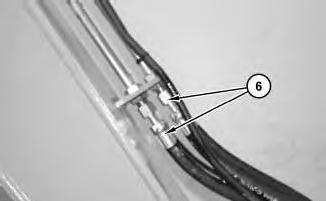
5. Disconnect hose assemblies (7).
Illustration
g01166429
g01166431
This is the sample of the manual
Click on the download link for complete Manual
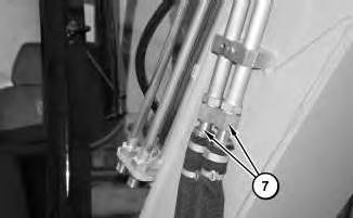
Illustration 7
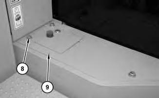
6. Remove bolts (8) and panel (9).
Illustration 8
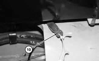
7. Disconnect harness assembly (10).
g01166433
Illustration 9
g01166435
g01166432