

Product: MINI HYD EXCAVATOR
Model: 304C CR MINI HYD EXCAVATOR FPK
Configuration: 304 C CR Mini Hydraulic Excavator FPK00001-UP (MACHINE) POWERED BY S4Q2T Engine
Disassembly and Assembly
S4Q2 Engine
Media Number -KENR6787-03 Publication Date -01/01/2013 Date Updated -29/01/2013
Electrical System - Install
SMCS - 1400-012
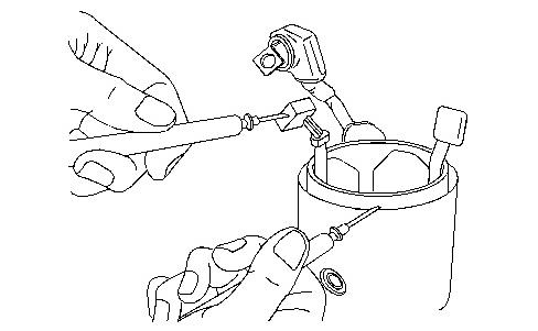
Installing glow plug
i04037734
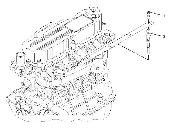
1
1. Tighten the nuts (1) to 1.3 ± 0.2 N·m (11.5 ± 1.8 lb in).
2. Tighten the glow plugs (2) to 18 ± 2 N·m (159 ± 18 lb in).
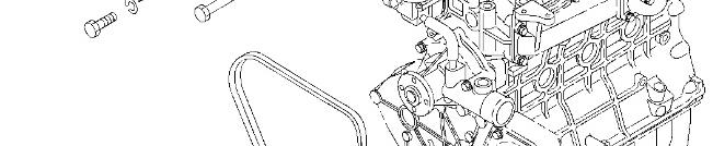
Installing alternator


Installing starter
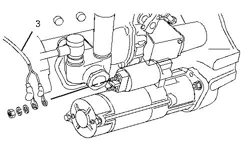
Illustration 3 g02241354
(3) Tighten the terminal B to ... 11 ± 1 N·m (97 ± 9 lb in.)
Copyright 1993 - 2021 Caterpillar Inc. All Rights Reserved. Private Network For SIS Licensees.
Tue Oct 19 10:53:51 UTC+0530 2021
Product: MINI HYD EXCAVATOR
Model: 304C CR MINI HYD EXCAVATOR FPK
Configuration: 304 C CR Mini Hydraulic Excavator FPK00001-UP (MACHINE) POWERED BY S4Q2T Engine
Disassembly and Assembly
S4Q2 Engine
Media Number -KENR6787-03 Publication Date -01/01/2013 Date Updated -29/01/2013
Electrical System - Disassemble/Inspect/Assemble
SMCS - 1400-040; 1400-017
Inspection before disassembling starter
Inspecting magnetic switch
i04021070
Perform the inspection as described below. If faulty, replace the magnetic switch with a new one.
Note: Do not apply current continuously for longer than 10 seconds.
1. Disconnect the connector of M terminal.
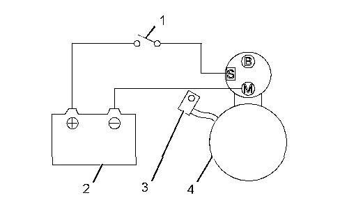
Illustration 1 g02241193
Pull-in test
(1) Switch
(2) Battery 24 V
(3) Disconnect connector
(4) Starter
2.
Connect the starter to the circuit as shown in the illustration. The magnetic switch is normal if the pinion springs out when the switch is turned ON.
Connect the starter to the circuit as shown in the Illustration. Pull out the pinion fully by hand. The magnetic switch is normal if the pinion does not return when it is released.
This is the sample of the manual
Click on the download link for complete Manual


3
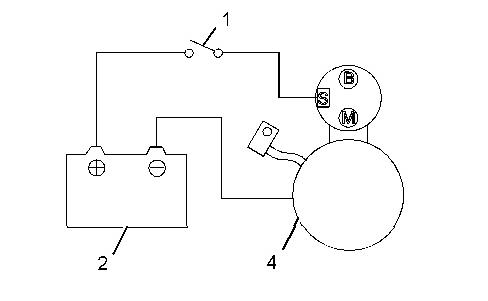
Return test
4. Return test
Connect the starter to the circuit as shown in the Illustration. Pull out the pinion fully by hand. The magnetic switch is normal if the pinion returns immediately when it is released.
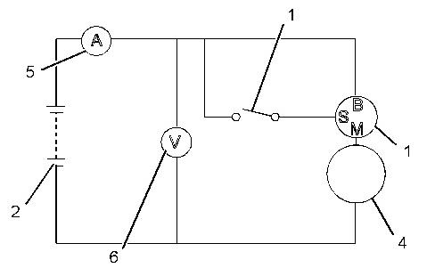
No load test
Note: Use as thick a wire as possible and firmly tighten each terminal. When detecting the rotation at the tip of the pinion, be careful, as the pinion pops out during operation.
4
(1) Switch
(2) Battery 24 V
(4) Starter
(5) Ammeter
(6) Voltmeter
1. Connect the starter to the circuit as shown in the Illustration.
2. In normal condition, the pinion pops out when the switch is turned ON, and the starter rotates at or more the specified rotation speed. If the terminal voltage, current or rotation speed does not meet the standard, disassemble, inspect, and repair the starter.
Table 1
Item Standard
No-load characteristics
Terminal voltage 11 V Current 130 A or less
Rotation speed 3600 rpm or more
Disassembling and inspecting starter
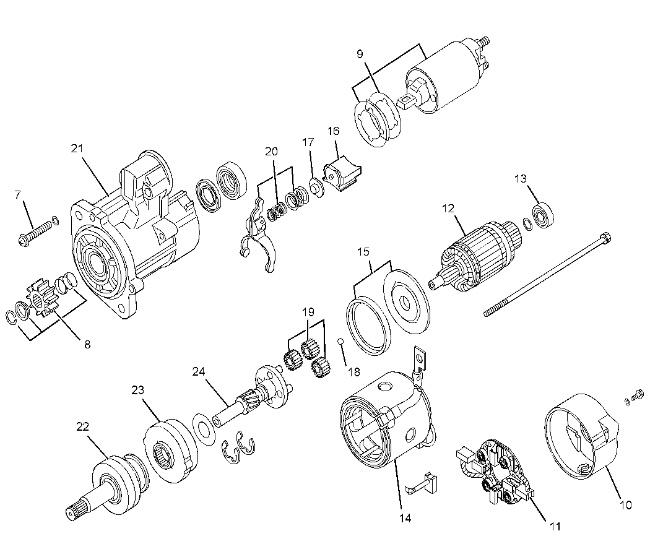
Illustration 5
Disassembling sequence
(7) Bolt
(8) Pinion set
(9) Magnet switch
(10) Rear bracket
(11) Brush holder
(12) Armature
(13) Bearing
(14) Yoke
(15) Packing
(16) Packing
(17) Plate
(18) Ball
(19) Planetary gear
(20) Lever
(21) Front bracket
(22) Overrunning clutch
(23) Internal gear
(24) Gear shaft
Inspect the following starter components:
Starter components Checks for
Pinion set (8) Pinion gear wear
Table 2
Remarks
Replace the lock rings.
Magnet switch (9) Open circuit or short circuit
Brush holder (11) Wear and insulation condition
Armature (12) Bend, deflection, open circuit, and short circuit of armature
Bearings (13) Looseness, abnormal noise, and rotation condition of bearings Replace
Yoke (14) Open circuit or short circuit
Planetary gear (19) Wear and damage of gear
Lever (20) Wear
Overrunning clutch (22) Proper function
Internal gear (23) Pinion gear wear
Gear shaft (24) Wear and damage of gear
Inspecting and repairing starter
Inspecting brushes for wear
Replace the lock rings.
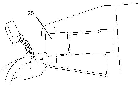
6 g02241213
Measure the length of the brushes (25). If the measured value is less than the limit, replace both the brush holder assembly and the brush assembly with new ones.
Table 3
mm (0.689 inch) 11.0 mm (0.43 inch)
Measuring brush spring load
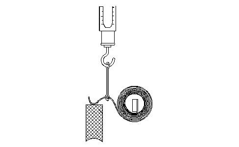
7 g02241214
Using a new brush, measure the spring load at which the spring lifts from the brush. If the measured value is less than the limit, replace the spring with a new one.
Table 4
load 26.70 to 36.10 N (6.00 to 8.11 lb) 14.7 N (3.3 lb)
Inspecting armature coil
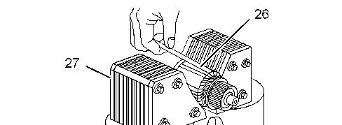

Illustration 8 g02241215
1. Inspect the armature coil using a growler tester (27). Hold a piece of iron plate against the armature core. If the iron plate (26) vibrates, replace the armature with a new one.
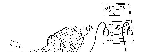
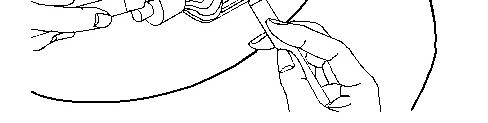
Illustration 9 g02241216
Inspecting insulation between commutator and shaft
2. Check that there is no continuity between the commutator and the shaft (core). If any continuity is observed, replace the armature with a new one.
Measuring commutator radial runout
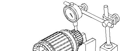
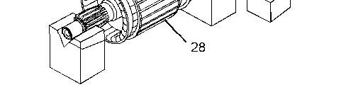
Illustration 10 g02241218
1. Inspect the commutator (28) surface. If the surface is rough, polish it using a 400 to 600 grit sandpaper.
2. Measure the commutator radial runout with a dial gauge. If the measured value exceeds the limit, replace the armature with a new one.
Measuring commutator outside diameter
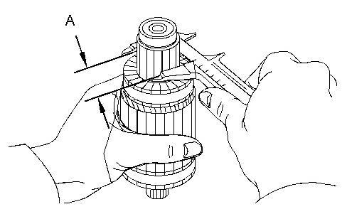
Illustration 11 g02241219
Measure the commutator outside diameter. If the measured value is less than the limit, replace the armature with a new one.
Table 5
Inspecting brush holder for insulation
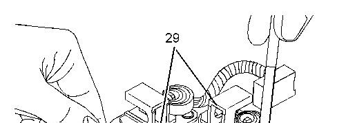
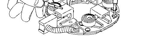
Illustration 12 g02241220 (29) Brush holder
Check that there is no continuity between each brush holder and the brush holder base. If continuity is observed, replace the whole brush holder assembly. Check the brush holders for looseness.
Measuring undercut depth
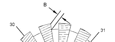
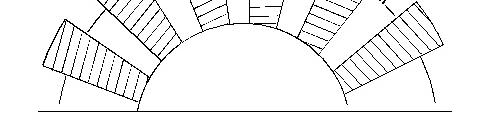
Illustration 13 g02241233
Measuring commutator mica depth (31) Mica
Measure the depth of undercutting between the commutator segments (30). If the measured value is less than the limit, repair or replace with a new part.
Table 6
Item Standard Limit
Undercutting depth (B)
Inspecting overrunning clutch
mm (0.020 inch)
Note: Do not clean the overrunning clutch in wash oil.
mm (0.008 inch)
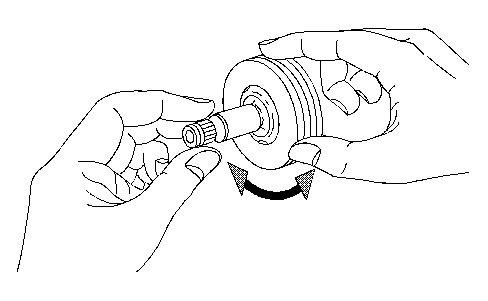
Illustration 14 g02241234
Make sure that, when attempting to turn the overrunning clutch, it locks in one direction and rotates smoothly in the opposite direction.
Inspecting continuity of magnetic switch (between M terminal and case)
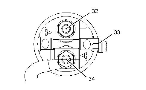
Illustration 15 g02241235
(32) Terminal B
(33) Terminal S
(34) Terminal M
Check that there is continuity between M terminal and case. If no continuity is observed, replace the magnetic switch with a new one.
Inspecting insulation of magnetic switch (between M terminal and B terminal)
Check that there is no continuity between M terminal and B terminal. If continuity is observed, replace the magnetic switch with a new one.
Inspecting continuity of yoke assembly
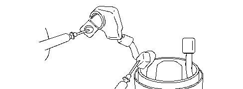
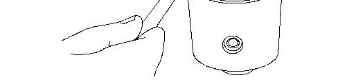
Illustration 16 g02241237
Check that there is continuity between M terminal of field coil and the lead wire for the brush. If no continuity is observed, replace the yoke assembly with a new one.
Inspecting insulation between yoke body and brush
17 g02241238
Check that there is no continuity between yoke body and brush. If continuity is observed, replace the yoke assembly with a new one.
Reassembling starter
Applying grease
Note: To avoid mixing of different greases, remove old grease before applying new grease. Make sure that the starter mounting surface, brushes, commutator, and other electric current conducting components are free from grease.
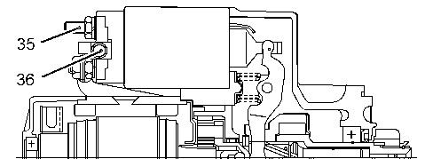
Illustration 18 g02241239
1. When overhauling the starter, apply grease to the following sliding surfaces, gears, and bearings.
2. Tighten the nut (35) to 10.8 ± 1.0 N·m (95.0 ± 9.0 lb in).
3. Tighten the bolt (36) to 3.32 ± 0.77 N·m (29.00 ± 7.00 lb in).
Inspecting and adjusting after reassembling
Inspecting pinion clearance
Note: Do not apply current continuously for longer than 10 seconds.
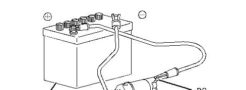
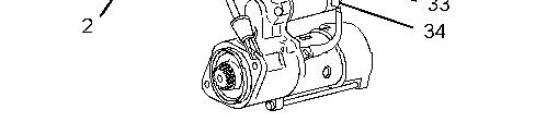
Illustration 19 g02241253
Adjusting pinion gap
(2) Battery
(33) Terminal S
(34) Terminal M
1. Since, connecting the wires of the reassembled starter as shown that in the diagram causes the pinion to extends and rotate slowly. Disconnect the connector from terminal M to stop the rotation.


Illustration 20 g02241254
2. Lightly push the tip of the extended pinion shaft with a finger. Measure the distance of the shaft movement to obtain the pinion gap measurement. Adjust the pinion gap by varying the number of packings installed at the magnetic switch section so that it conforms to the standard value. When the number of packings is increased, the pinion gap decreases. If proper adjustment cannot be achieved by varying the number of packings, replace the lever.
Table 7
Pinion gap (C)
No load test
0.50 to 2.00 mm (0.020 to 0.079 inch)
Note: Use as thick a wire as possible and firmly tighten each terminal. When detecting the rotation at the tip of the pinion, be careful, as the pinion pops out during operation.
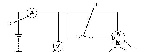
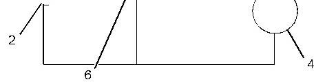
Illustration 21 g02241196
Test at no load
(1) Switch
(2) Battery 24 V
(4) Starter
(5) Ammeter
(6) Voltmeter
1. Connect the starter to the circuit as shown in the Illustration.
2. In normal condition, the pinion pops out when the switch is turned ON, and the starter rotates at or more the specified rotation speed. If the terminal voltage, current or rotation speed does not meet the standard, disassemble, inspect, and repair the starter.
Disassembling, inspecting, and reassembling alternator
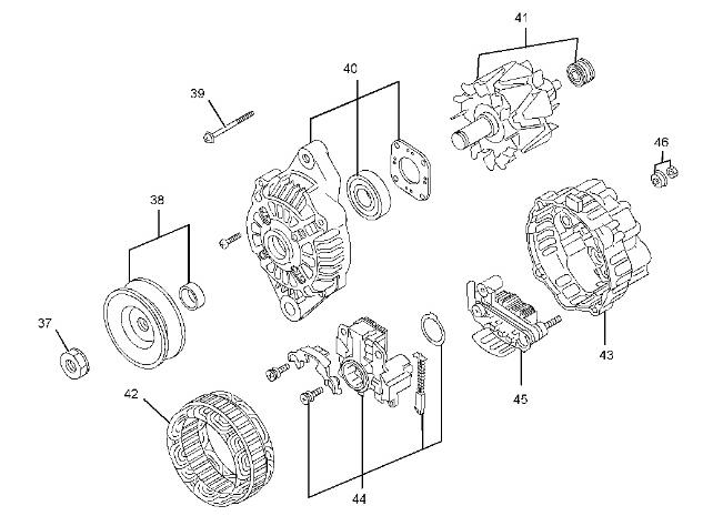
Illustration 22
Disassembling sequence
(37) Nut
(38) Pulley, spacer
(39) Through bolt
(40) Front bracket, bearing
(41) Rotor, bearing
(42) Stator
(43) Rear bracket
(44) Regulator
(45) Rectifier
(46) Nut set
Inspect the following alternator components:
Table 8
Alternator components Checks for Remarks
Pulley, spacer (38) Deformation and damage
Front bracket, bearing (40)
Rotor, bearing (41)
Crack, damage of front bracket, and rotation of bearing
Dirt, damage, seizure of slip ring, coil resistance, and rotation of bearing
Stator (42) Broken wire and ground of coil
Rear bracket (43) Crack and damage
Regulator (44) Sliding state and wear of brushes
Rectifier (45) Short circuit and open circuit
Separating front bracket from stator
Note: Do not disassemble the alternator unless the repair is necessary. Do not insert the screwdrivers too deep, as it can damage the stator.
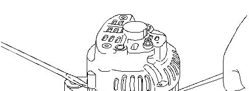

Illustration 23 g02241274
1. Remove the through bolts.
2. With two flat-head screwdrivers inserted between the front bracket and stator, pry apart.
Removing pulley
Note: When setting the rotor in a vise, be sure to hold the base of the rotor claw. Do not hold the rotor claw, as damage the claw.
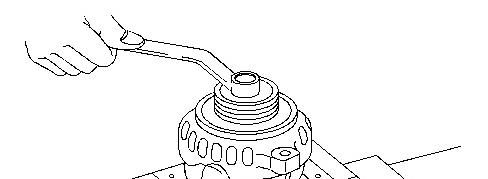
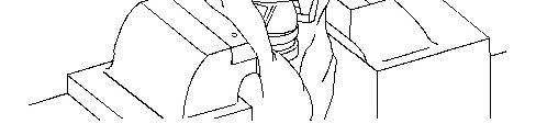
Illustration 24 g02241275
1. Apply a cloth to the rotor and set it in a vise.
2. Remove the pulley nut and then pull out the pulley and spacer.
3. Remove the rotor from the front bracket.
Removing stator
Note: Unsoldering must be finished as quickly as possible. Extended heating will damage the diodes.
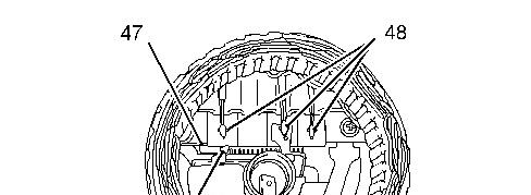

25 g02241277
(47) Rectifier
(48) Soldering
1. Cut off the joint of the stator and remove the stator from the rectifier.
2. Unscrew the rectifier mounting screws, and dismount the rectifier.
Inspecting rectifier
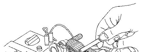
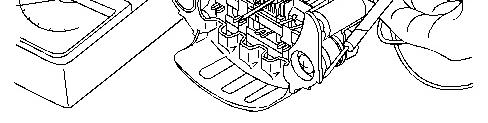
Illustration 26 g02241278
Check that diodes in a rectifier function properly. To check, measure both negative (-) and positive (+) resistance alternately twice. If both infinite negative and infinite positive resistances are observed, case, replace the rectifier with a new one.

Note: Use a wide measuring range as much as possible. The current flow during test is much lower than the current that normally flows in the rectifier, by which the accurate resistance may not be measured using a tester. This tendency is noticeable if the measuring range is small.
Inspecting rotor

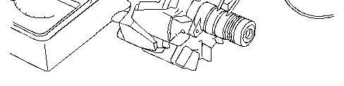
Illustration 27 g02241279
1. Check that there is continuity between slip rings. If no continuity is observed, replace the rotor with a new one.
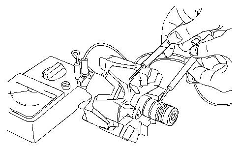
Illustration 28 g02241280
2. Check that there is no continuity between the slip ring and the shaft (or the core). If continuity is observed, replace the rotor with a new one.
Inspecting stator
This is the sample of the manual
Click on the download link for complete Manual

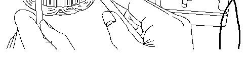
Illustration 29 g02241281
1. Checking continuity between lead wires Check that there is continuity between a pair of lead wires. Also check that there is no continuity between a pair of lead wires and other pair of lead wires. If defective, replace the stator.
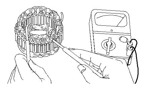
Illustration 30 g02241282
2. Checking insulation between lead wire and core Check that there is no continuity between each lead wire and the stator core. If continuity is observed, replace the stator.
Note: The core cannot be replaced as a single item.
Inspecting brushes for wear