

Product: MINI HYD EXCAVATOR
Model: 304.5 MINI HYD EXCAVATOR WAK
Configuration: 304.5 Mini Hydraulic Excavator WAK00001-UP (MACHINE) POWERED BY 3024 Engine
Disassembly and Assembly
304.5 Mini Hydraulic Excavator
Media Number -RENR3543-01 Publication Date -01/09/2001 Date Updated -16/11/2001
i01324145
Air Cleaner - Remove and Install
SMCS - 1051-010; 1054-010
Removal Procedure
1
2
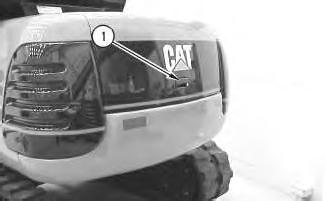
2. Disconnect electrical connector (2) .
3. Loosen clamps (3) and (5) .
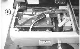
4. Disconnect hoses (4) and (6) .
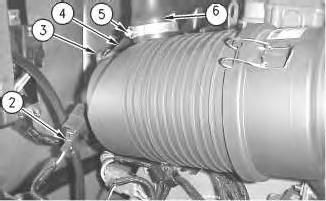
Illustration 3
5. Remove two bolts (8) and washers.
6. Remove air cleaner (7) .
Installation Procedure
4
1. Position air cleaner (7) .
2. Install washers and two bolts (8) to the air cleaner. Tighten the bolts.
5
3. Connect electrical connector (2) .
4. Connect hoses (4) and (6) to the air cleaner.
5. Tighten clamps (3) and (5) .

Copyright 1993 - 2020 Caterpillar Inc. All Rights Reserved. Private Network For SIS Licensees. Tue Sep 15 14:39:38 UTC+0530 2020
Product: MINI HYD EXCAVATOR
Model: 304.5 MINI HYD EXCAVATOR WAK
Configuration: 304.5 Mini Hydraulic Excavator WAK00001-UP (MACHINE) POWERED BY 3024 Engine
Disassembly and Assembly
304.5 Mini Hydraulic Excavator
i01337927
Alternator - Remove and Install
SMCS - 1405-010
Removal Procedure
Start By:
A. Remove the battery and battery cable. Refer to Disassembly and Assembly, "Battery and Battery Cable - Remove and Install".
B. Remove the seat. Refer to Disassembly and Assembly, RENR 3548, "Seat - Remove and Install".
Note: Put identification marks on all wires for installation purposes.

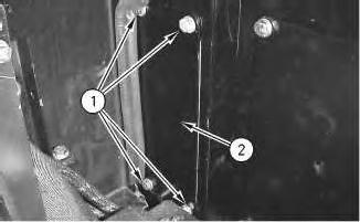
Illustration 1 g00676426
1. Remove four bolts (1) and washers.
This is the sample of the manual
Click on the download link for complete Manual
2. Remove access panel (2) .
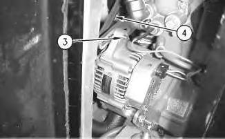
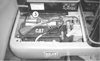
Illustration 2
3. Remove bolt (3) and the washer.
4. Move the alternator toward the engine in order to relieve tension on the V-Belt (4) .
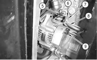
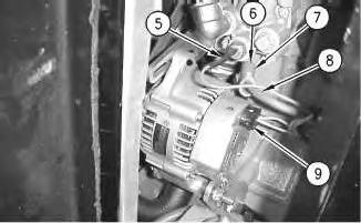
Illustration 3
5. Disconnect wires (5) and (9) .
6. Move rubber cover (6) aside .
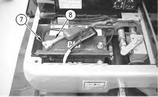
7. Remove locknut (7) .
8. Disconnect cable (8) from the alternator.
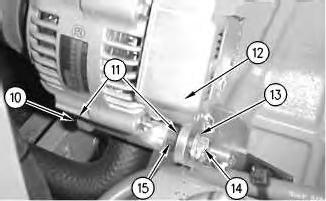
Illustration 4
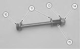
Illustration 5
9. Remove nut (15) and washer (13) .
10. Remove bolt (10) and washers (11) .
11. Remove alternator (12) and spacer (14) through the access panel.
Installation Procedure
Illustration 6
Illustration 7
1. Install spacer (14) to the alternator bracket and place alternator (12) through the access panel.
2. Install washers (11) and bolt (10) .
3. Install washer (13) and nut (14) .
4. Tighten the nut and the bolt.
8
5. Connect wires (5) and (9) .
6. Connect cable (8) to the alternator with locknut (7). Tighten the locknut.
7. Place the rubber cover (6) onto the cable.

Illustration 9
8. Place V-Belt (4) on the alternator pulley.
9. Install the washer and bolt (3). Do not tighten the bolt at this time. Pull the alternator away from the engine in order to tension the V-Belt. Tighten the bolt to a torque of 28 ± 7 N·m (21 ± 5 lb ft).
10. Place access panel (2) in position.
11. Install washers and bolts (1). Tighten the bolts.
, End By:
a. Install the seat. Refer to Disassembly and AssemblyRENR 3548, "Seat - Remove and Install".
b. Install the battery and battery cable. Refer to Disassembly and Assembly, "Battery and Battery Cable - Remove and Install".
Product: MINI HYD EXCAVATOR
Model: 304.5 MINI HYD EXCAVATOR WAK
Configuration: 304.5 Mini Hydraulic Excavator WAK00001-UP (MACHINE) POWERED BY 3024 Engine
Disassembly and Assembly
304.5 Mini Hydraulic Excavator
Media Number -RENR3543-01
Date -01/09/2001
Battery and Battery Cable - Separate and Connect
SMCS - 1401-029
Removal Procedure

Illustration 1 g00703233
1. Remove bolt (2) and the washer.
2. Remove battery cover (1) .
Updated -16/11/2001
i01328261
2
3. Move rubber battery cover (3) aside.
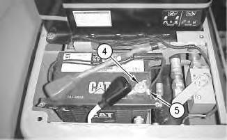
Illustration 3
4. Loosen nut (5) and disconnect battery cable (4) on the negative terminal of the battery.
Note: Do not allow the disconnected battery cable to contact the frame of the machine.
4
5. Move rubber battery cover (6) aside.
5
6. Loosen nut (7) and disconnect battery cable (8) on the positive terminal of the battery.
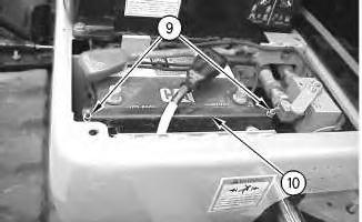
Illustration 6 g00706233
7. Remove two nuts (9) and washers.
8. Remove bracket (10) from the battery.

Illustration 7
9. Remove battery (11) from the machine.
Installation Procedure
g00706238
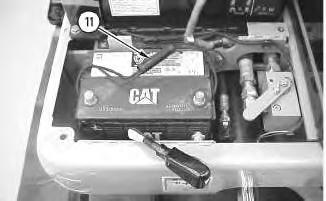
Illustration 8
1. Place battery (11) in position.
g00706238

9
2. Install bracket (10) to the battery.
3. Install washers and two nuts (9) to the bracket. Tighten the nuts.
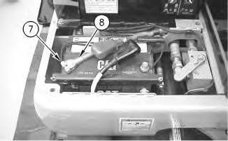
Illustration 10
g00706224
4. Connect battery cable (8) onto the positive terminal of the battery and tighten the nut (7) .
11
5. Install rubber battery cover (6) onto the battery terminal.
Note: Do not allow the disconnected battery cable to contact the frame of the machine.
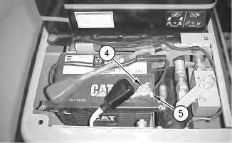
Illustration 12
g00703239
6. Connect battery cable (4) onto the negative terminal of the battery and tighten the nut (5) .
13
7. Install rubber battery cover (3) onto the battery terminal.
Illustration 14
8. Install battery cover (1) .
9. Install the washer and bolt (2). Tighten the bolt.
Copyright 1993 - 2020 Caterpillar Inc. All Rights Reserved. Private Network For SIS Licensees. Tue Sep 15 14:36:32 UTC+0530 2020
Product: MINI HYD EXCAVATOR
Model: 304.5 MINI HYD EXCAVATOR WAK
Configuration: 304.5 Mini Hydraulic Excavator WAK00001-UP (MACHINE) POWERED BY 3024 Engine
Disassembly and Assembly
304.5 Mini Hydraulic Excavator Media
i01328262
Bottom Guard - Remove and Install
SMCS - 7153-010
Removal Procedure

Illustration 1 g00666707
1. Remove four bolts (1) and washers.
2. Remove the bottom guard (2) .
Installation Procedure
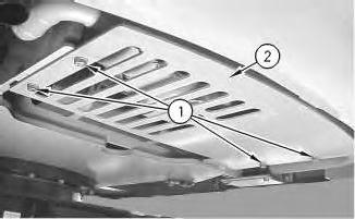
Illustration 2 g00666707
1. Place bottom guard (2) in position.
2. Install washers and four bolts (1) to the bottom guard. Tighten the bolts.
Copyright 1993 - 2020 Caterpillar Inc. All Rights Reserved. Private Network For SIS Licensees.
Product: MINI HYD EXCAVATOR
Model: 304.5 MINI HYD EXCAVATOR WAK
Configuration: 304.5 Mini Hydraulic Excavator WAK00001-UP (MACHINE) POWERED BY 3024 Engine
Disassembly and Assembly
304.5 Mini Hydraulic Excavator
i01337928
Electric Starting Motor - Remove and Install
SMCS - 1453-010
Removal Procedure
Start By:
A. Remove the battery and battery cable. Refer to Disassembly and Assembly, "Battery and Battery Cable - Remove and Install".
B. Remove the seat. Refer to Disassembly and Assembly, RENR 3548, "Seat - Remove and Install".
Note: Put identification marks on all wires for installation purposes.
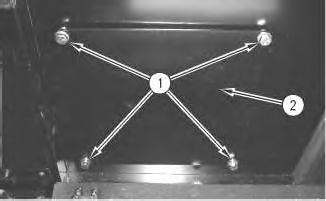
Illustration 1 g00707569
1. Remove four bolts (1) and washers.
2. Remove access panel (2) .
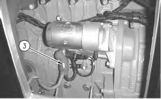
Illustration 2
3. Move rubber cover (3) aside.

Illustration 3
4. Remove nut (4) .
5. Disconnect two electrical wires (5) and (6) .
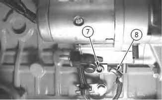
Illustration 4
6. Remove screw (7) and disconnect wire (8) .
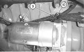
Illustration 5
g00707575
7. Cut straps (9) and move wire (10) aside in order to gain access to the bolt.

Illustration 6
8. Remove two bolts (11) and washers.
9. Remove electric starting motor (12) through the access panel.
Installation Procedure
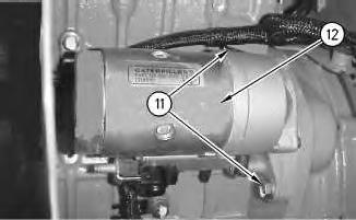
Illustration 7
g00707579
1. Place electric starting motor (12) through the access panel.
2. Install washers and bolts (11) to the electric starting motor. Tighten the bolts.
Illustration 8
3. Secure wire (10) with new straps (9) .
Illustration 9
4. Connect wire (8) to the electric starting motor by tightening screw (7) .
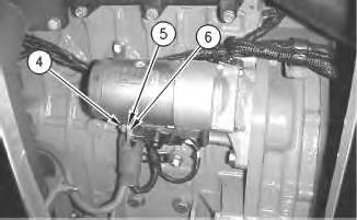
Illustration 10
5. Connect two electrical wires (5) and (6) to the electric starting motor.
6. Install nut (4). Tighten the nut.

11
7. Place rubber cover (3) onto the electrical wires.
12
8. Place access panel (2) in position.
9. Install washers and four bolts (1) to the access panel. Tighten the bolts.
, End By:
a. Install the seat. Refer to Disassembly and AssemblyRENR 3548, "Seat - Remove and Install".
b. Install the battery and battery cable. Refer to Disassembly and Assembly, "Battery and Battery Cable - Remove and Install".
This is the sample of the manual
Click on the download link for complete Manual
Product: MINI HYD EXCAVATOR
Model: 304.5 MINI HYD EXCAVATOR WAK
Configuration: 304.5 Mini Hydraulic Excavator WAK00001-UP (MACHINE) POWERED BY 3024 Engine
Disassembly and Assembly
304.5 Mini Hydraulic Excavator Media Number -RENR3543-01
i01345830
Engine - Install
SMCS - 1000-012
Installation Procedure
Table 1 Required Tools
A 138-7575 Link Bracket 2

Illustration 1 g00710718
1. Use Tooling (A) and a suitable lifting device to place engine (50) into position. Weight of the engine is 227 kg (500 lb).