

PreviousScreen
Product: MINI HYD EXCAVATOR
Model: 301.6 MINI HYD EXCAVATOR BDH
Shutdown SIS
Configuration: 301.5 301.6 301.8 Mini Hydraulic Excavator BDH00001-UP (MACHINE) POWERED BY 3003 Engine
Disassembly and Assembly
301.5, 301.6 and 301.8 Mini-Hydraulic Excavator Engine Supplement
Air Cleaner - Remove and Install
SMCS - 1051-010; 1054-010
Removal Procedure
i00796496
Note: Put identification marks on all lines, on all hoses, on all wires, and on all tubes for installation purposes. Plug all lines, all hoses and all tubes. This helps to prevent fluid loss and this helps to keep contaminants from entering the system.
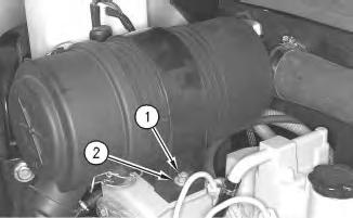
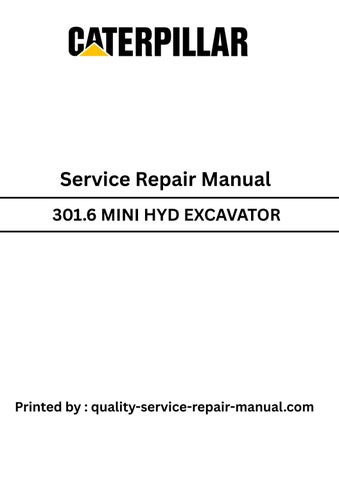
Illustration 1 g00374292
1. Remove two nuts (1) and remove two washers (2) .

2
2. Remove electrical plug (3) .
3. Loosen hose clamp (4) .
4. Remove air cleaner (5) .
Installation Procedure
3
1. Install air cleaner (5) .
2. Install hose clamp (4) and tighten.
3. Install electrical plug (5) .
4
4. Install washers (2) and install two nuts (1) .
Copyright 1993 - 2020 Caterpillar Inc. All Rights Reserved. Private Network For SIS Licensees.
Fri May 1 10:18:49 UTC+0530 2020
PreviousScreen
Product: MINI HYD EXCAVATOR
Model: 301.6 MINI HYD EXCAVATOR BDH
Configuration: 301.5 301.6 301.8 Mini Hydraulic Excavator BDH00001-UP (MACHINE) POWERED BY 3003 Engine
Disassembly and Assembly
301.5, 301.6 and 301.8 Mini-Hydraulic Excavator Engine Supplement Media
-RENR2803-01
Alternator - Remove and Install
SMCS - 1405-010
Removal Procedure
Start By:
A. Remove the seat. Refer to Disassembly and Assembly, RENR2808, "Seat - Remove and Install" .
B. Drain the coolant. Refer to Operation and Maintenance, SEBU7152, "Cooling System Coolant (DEAC) - Change" .
NOTICE
Care must be taken to ensure that fluidsare contained during performance of inspection, maintenance, testing, adjusting and repair of the machine. Be prepared to collect the fluidwith suitable containers before opening any compartment or disassembling any component containing fluids.
Refer to Special Publication, NENG2500, "Caterpillar Tools and Shop Products Guide", for tools and supplies suitable to collect and contain fluids in Caterpillar machines.
Dispose of all fluids according to local regulationsand mandates.
Note: Remove the negative lead of the battery.
1
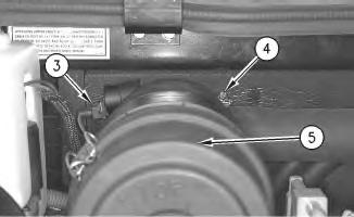
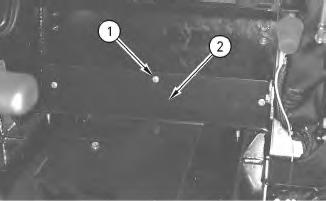
1. Remove six bolts and washers (1) .
2. Remove panel (2) .

2
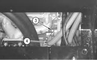
3. Remove electrical plug (3) .
4. Remove electrical plug (4) .
5. Remove the bolt and washer (5) .
3
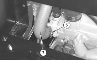
6. Loosen hose clamp (6) and position hose (7) away from the work area.

Illustration 4
7. Remove the washer and bolt (8) .
8. Remove the washer and bolt (9) .
9. Remove bracket assembly (10) .
This is the sample of the manual
Click on the download link for complete Manual
5
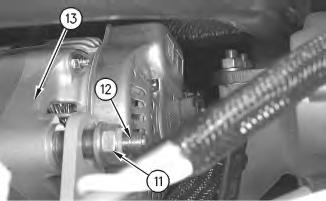
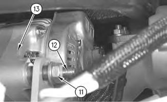
10. Remove nut (11) .
11. Remove bolt (12) .
12. Remove alternator (13) .
Installation Procedure
6
1. Install alternator (13) .
2. Install bolt (12) .
3. Install nut (11) .

7
4. Install bracket assembly (10) .
5. Install the washer and bolt (9) .
6. Install the washer and bolt (8) .

Illustration 8
g00465585
7. Install hose (7) and tighten hose clamp (6) to a torque of 3.5 ± 0.5 N·m (31 ± 4.5 lb in) .
Illustration 9
8. Install the bolt and washer (5) .
9. Install electrical plug (4) .
10. Install electrical plug (3) .
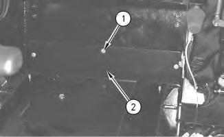
Illustration 10
11. Install panel (2) .
12. Install six bolts and washers (1) .
13. Install the negative lead on the battery. ,,
End By:
a. Install the seat. Refer to Disassembly and AssemblyRENR2808, "Seat - Remove and Install" . b. Fill with coolant. Refer to Operation and MaintenanceSEBU7152, "Cooling System Coolant (DEAC) - Change" .
Copyright 1993 - 2020 Caterpillar Inc.
PreviousScreen
Product: MINI HYD EXCAVATOR
Model: 301.6 MINI HYD EXCAVATOR BDH
Shutdown SIS
Configuration: 301.5 301.6 301.8 Mini Hydraulic Excavator BDH00001-UP (MACHINE) POWERED BY 3003 Engine
Disassembly and Assembly
301.5, 301.6 and 301.8 Mini-Hydraulic Excavator Engine Supplement Media
Electric Starting Motor - Remove and Install
SMCS - 1453-010
Removal Procedure
Start By:
A. Remove the seat. Refer to Disassembly and Assembly, RENR2808, "Seat - Remove and Install" .
Note: Disconnect the negative lead on the battery before you work on the machine.
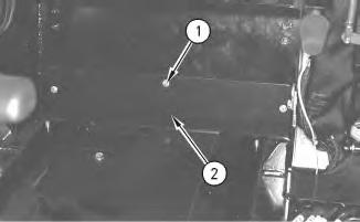
1. Remove six bolts and six washers (1) and remove access panel (2) .
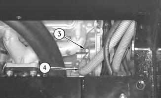
2
2. Remove one bolt and one washer (3) and remove battery cable (4) .
Note: Perform the following three steps from the underside of the machine.
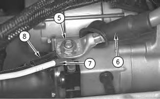
3
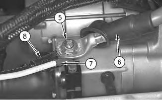
3. Remove nut (5) .
4. Remove electrical wires (6) , (7) , and (8) .
4
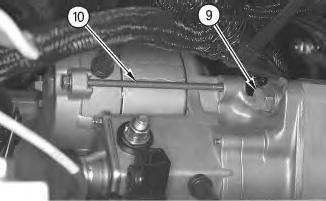
5. Remove one bolt and one washer (9) .
6. Remove electric starting motor (10) through the access panel.
Installation Procedure
Illustration 5
g00441908
1. Install electric starting motor (10) through the access panel.
Note: Perform the following three steps from the underside of the machine.
2. Install the bolt and washer (9) .
6
7
8
6. Install access panel (2) and install six bolts and six washers (1) .
7. Connect the negative lead on the battery. , End By: Install the seat. Refer to Disassembly and AssemblyRENR2808, "Seat - Remove and Install".
PreviousScreen
Product: MINI HYD EXCAVATOR
Model: 301.6 MINI HYD EXCAVATOR BDH
Shutdown SIS
Configuration: 301.5 301.6 301.8 Mini Hydraulic Excavator BDH00001-UP (MACHINE) POWERED BY 3003 Engine
Disassembly and Assembly
301.5, 301.6 and 301.8 Mini-Hydraulic Excavator Engine Supplement Media
Engine and Pumps - Install
SMCS - 1017-012; 1024-012
Installation Procedure Table 1
A 6V-2157 Link Bracket 2
Personal injury canresult from hydraulic oil pressure and hot oil.
Hydraulic oil pressure can remain in the hydraulic system after the engine hasbeen stopped. Seriousinjury canbe caused if this pressure is not released before any service is done onthe hydraulic system.
Make sure all of the attachmentshave beenlowered, oil is cool before removing any componentsor lines. Remove the oil filler cap only when the engine is stopped, andthe filler cap is cool enough to touch with your bare hand.
At operating temperature, the engine coolant ishot andunder pressure.
Steam can cause personal injury.
Check the coolant level only after the engine hasbeen stopped and the fill cap is cool enough to touch with your bare hand.
Remove the fill cap slowly to relieve pressure.
Cooling system conditioner contains alkali. Avoid contact with the skin and eyes to prevent personal injury.
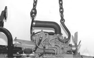
1. Apply suitable lifting chains to the lifting pointson the engine. Apply enough tension on the chains in order to support the weight of the engine.
2. Lower the engine and pumps into position in the engine compartment. The weight of the engine and pumps is 125 kg (275 lb) .
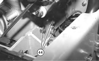
2
3. Install six bolts and washers (44) . The other three boltsare located on the rear of the engine.

3
4. Install two nutsand two washers (43) .
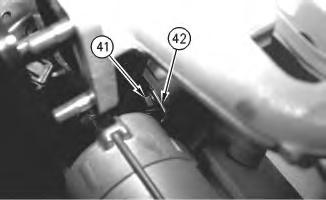
Illustration 4
5. Install electrical clip (42) .
6. Install the bolt and washer (41) .
g00489579
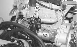
Illustration 5
g00489577
7. Install the exhaust manifold and install four nuts (40) .
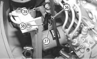
Illustration 6
8. Install ground cable (39) .
9. Install clip (38) .
10. Install the bolt and washer (37) .
11. Install nut (36) .
g00489569
7
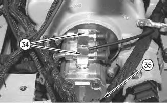
12. Install hose (35) and tighten the hose clamp.
13. Install two hoses (34) .
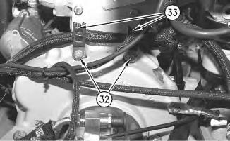
8
14. Install two electrical clips (33) .
15. Install the two boltsand washers (32) .
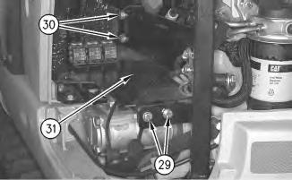
9
16. Install plate assembly (31) .
17. Install the wires. Install two boltsand washers(30) .
18. Install two bolts and washers (29) .
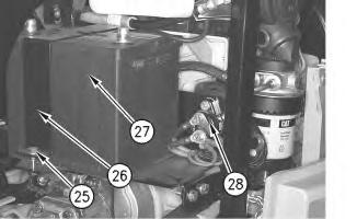
Illustration 10
19. Install electrical reset (28) and install two bolts.
20. Install battery (27) .
21. Install battery bracket (26) .
22. Install the bolt and washer (25) .
23. Connect the battery cables.
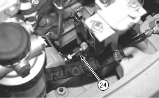
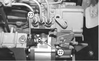

13
27. Place the engine throttle cable in position and tighten nut (21) .
28. Install pin (20) and install clip (19) .
14
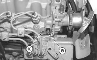
15
30. Install wire (16) and install bolt (15) .
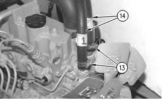
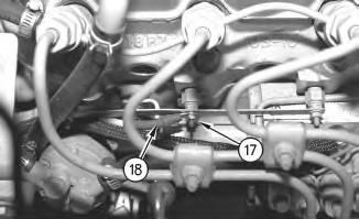
16
31. Install two hoses (14) and tighten two hose clamps (13) .
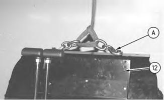
Illustration 17 g00489258
Note: The seat is removed for photographic purposes.
32. Install tooling (A) and apply suitable lifting straps.
33. Install wall plate assembly (12) .
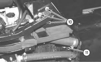
Illustration 18
34. Install two bolts and washers (11) .
35. Install three bolts and washers (10) .

Illustration 19
36. Install two bolts and washers (9) .
37. Install three bolts and washers (8) .
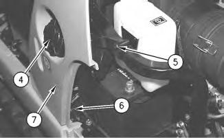
Illustration 20
38. Remove fuel tank cap (4) and install side panel (7) .
39. Install the bolt and washer (6) .
40. Install bolt (5) .
41. Install fuel tank cap (4) .
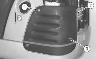
Illustration 21 g00465682
42. Install left side corner protector (3) .
43. Tighten two bolts (2) .
44. Install the two boltsand washers (1) .
End By:
a. Install the cab. Refer to Disassembly and AssemblyRENR2808, "Cab - Install".
b. Install the alternator. Refer to Disassembly and AssemblyRENR2803, "Alternator - Remove and Install" .
c. Install the electric starting motor. Refer to Disassembly and AssemblyRENR2803, "Electric Starting Motor - Remove and Install" .
d. Install the radiator. Refer to Disassembly and AssemblyRENR2803, "Radiator and FanRemove and Install" .
e. Install the hood. Refer to Disassembly and AssemblyRENR2803, "Hood - Remove and Install" .
1993 - 2020 Caterpillar Inc.
Network For SIS Licensees. Fri May 1 10:21:21 UTC+0530 2020
PreviousScreen
Product: MINI HYD EXCAVATOR
Model: 301.6 MINI HYD EXCAVATOR BDH
Configuration: 301.5 301.6 301.8 Mini Hydraulic Excavator BDH00001-UP (MACHINE) POWERED BY 3003 Engine
Disassembly and Assembly
301.5, 301.6 and 301.8 Mini-Hydraulic Excavator Engine Supplement
Engine and Pumps - Remove
SMCS - 1017-011; 1024-011
Removal Procedure
Table 1
A 6V-2157 Link Bracket 2
Start By:
A. Remove the hood. Refer to Disassembly and Assembly, RENR2803, "Hood - Remove and Install" .
B. Remove the radiator. Refer to Disassembly and Assembly, RENR2803, "Radiator and FanRemove and Install" .
C. Remove the electric starting motor. Refer to Disassembly and Assembly, RENR2803, "Electric Starting Motor - Remove and Install" .
D. Remove the alternator. Refer to Disassembly and Assembly, RENR2803, "Alternator - Remove and Install" .
E. Remove the cab. Disassembly and Assembly, RENR2808, "Cab - Remove" .
Personal injury canresult from hydraulic oil pressure and hot oil.
This is the sample of the manual
Click on the download link for complete Manual
Hydraulic oil pressure can remain in the hydraulic system after the engine hasbeen stopped. Seriousinjury canbe caused if this pressure is not released before any service is done onthe hydraulic system.
Make sure all of the attachmentshave beenlowered, oil is cool before removing any componentsor lines. Remove the oil filler cap only when the engine is stopped, andthe filler cap is cool enough to touch with your bare hand.
At operating temperature, the engine coolant ishot andunder pressure.
Steam can cause personal injury.
Check the coolant level only after the engine hasbeen stopped and the fill cap is cool enough to touch with your bare hand.
Remove the fill cap slowly to relieve pressure.
Cooling system conditioner contains alkali. Avoid contact with the skin and eyes to prevent personal injury.
NOTICE
Care must be taken to ensure that fluidsare contained during performance of inspection, maintenance, testing, adjusting and repair of the machine. Be prepared to collect the fluidwith suitable containers before opening any compartment or disassembling any component containing fluids.
Refer to Special Publication, NENG2500, "Caterpillar Tools and Shop Products Guide", for tools and supplies suitable to collect and contain fluids in Caterpillar machines.
Dispose of all fluids according to local regulationsand mandates.
Note: Put identification marks on all lines, on all hoses, on all wires, and on all tubes for installation purposes. Plug all lines, all hoses and all tubes. This helps to prevent fluid loss and this helpsto keep contaminantsfrom entering the system.