

Product: SKID STEER LOADER
Model: 272C SKID STEER LOADER RED
Configuration: 272C Skid Steer Loader RED00001-UP (MACHINE) POWERED BY 3044C Engine
Disassembly and Assembly
236B, 246B, 246C, 252B, 256C, 262B, 262C, 262C2 and 272C
Skid Steer Loaders Engine Supplement
Media Number -KENR5114-03
Publication Date -01/04/2011
Aftercooler - Remove and Install
SMCS - 1063-010
S/N- RED1-UP
S/N- TMW1-UP
Removal Procedure
Start By:
Date Updated -19/04/2011
i02667442
A. Remove the hydraulic tank. Refer to Disassembly and Assembly, "Hydraulic Tank - Remove".
NOTICE
Keep all parts clean from contaminants.
Contaminants may cause rapid wear andshortened component life.
NOTICE
Care must be taken to ensure that fluids are containedduring performance of inspection, maintenance, testing, adjusting and repair of the product. Be preparedto collect the fluid with suitable containers
before opening any compartment or disassembling any component containing fluids.
Refer to Special Publication, NENG2500, "Caterpillar Dealer Service Tool Catalog" for toolsand supplies suitable to collect and contain fluids on Caterpillar products.
Dispose of all fluids according to local regulations and mandates.
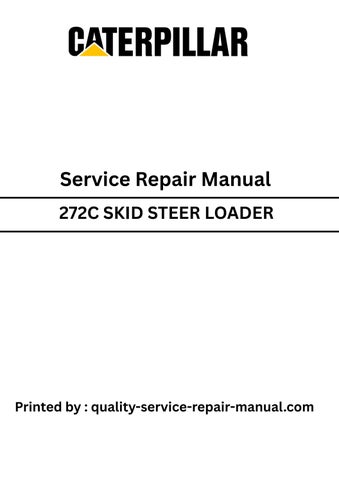
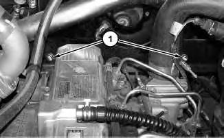
1
1. Remove bolts (1) and bolts(2) .
2. Lower the cab. Refer to Operation and Maintenance Manual, "Cab Tilting".
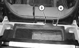
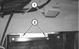
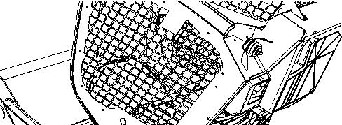
Illustration 2
3. Remove pin assembly (3) and raise grill assembly (4) .

4. Raise radiator (7). Refer to Operation and Maintenance Manual, "Radiator Tilting".
5. Loosen hose clamps (6) and remove tube (5) and the hosesasone.
Note: Note the position of hose clamps (6) for assembly purposes.
6. Loosen hose clamps (10) and remove hose (11) .
Note: Note the position of hose clamps (10) for assembly purposes.
7. Remove bolts (9) and duct assembly (8) .
8. Disconnect clips (13) and move hose (12) out of the way.
9. Remove aftercooler (14) from the machine.
Installation Procedure NOTICE
Keep all parts clean from contaminants.
Contaminants may cause rapid wear andshortened component life.
NOTICE
Care must be taken to ensure that fluids are containedduring performance of inspection, maintenance, testing, adjusting and repair of the product. Be preparedto collect the fluid with suitable containers before opening any compartment or disassembling any component containing fluids.
Refer to Special Publication, NENG2500, "Caterpillar Dealer Service Tool Catalog" for toolsand supplies suitable to collect and contain fluids on Caterpillar products.
Dispose of all fluids according to local regulations and mandates.
4 g01340465
Illustration 5
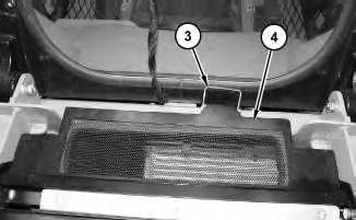
Illustration 6
1. Position aftercooler (14) to the machine.
2. Raise the cab. Refer to Operation and Maintenance Manual, "Cab Tilting".
3. Install bolts (2). Install bolts (1). Tighten bolts (1) to a torque of 15 ± 3 N·m (11 ± 2 lb ft).
4. Lower the cab. Refer to Operation and Maintenance Manual, "Cab Tilting".
5. Position duct assembly (8) and install bolts (9) .
6. Lower grill assembly (4) and install pin assembly (3) .
7. Position hose (12) and connect clips (13) .
8. Position hose (11) .
Note: Make sure that hose (11) is pushed onto the connections as far aspossible prior to tightening hose clamps(10) .
9. Tighten hose clamps (10) to a torque of 7.5 ± 1.0 N·m (66 ±9 lb in).
This is the sample of the manual
Click on the download link for complete Manual
Note: Make sure that hose clamps (10) are oriented in the correct position.
10. Position tube (5) and the hoses.
11. Tighten hose clamps (6) to a torque of 7.5 ± 1.0 N·m (66 ±9 lb in).
Note: Make sure that hose clamps (6) are oriented in the correct position.
12. Lower radiator (7). Refer to Operation and Maintenance Manual, "Radiator Tilting".
End By: Install the hydraulic tank. Refer to Disassembly and Assembly, "Hydraulic Tank - Install".
Product: SKID STEER LOADER
Model: 272C SKID STEER LOADER RED
Configuration: 272C Skid Steer Loader RED00001-UP (MACHINE) POWERED BY 3044C Engine
Disassembly and Assembly
236B, 246B, 246C, 252B, 256C, 262B, 262C, 262C2 and 272C
Skid Steer Loaders Engine Supplement
Media Number -KENR5114-03
Publication Date -01/04/2011
Aftercooler Fan and Mounting - Remove and Install
SMCS - 1063-010-HFN; 1063-010-MT
S/N- RED1-UP
S/N- TMW1-UP
Removal Procedure
Start By:
Date Updated -19/04/2011
i02672921
A. Remove the aftercooler fan motor. Refer to Disassembly and Assembly, "Gear Motor (Fan, Aftercooler) - Remove".
B. Remove the aftercooler. Refer to Disassembly and Assembly, "Aftercooler - Remove and Install".
C. Remove the refrigerant condenser. Refer to Disassembly and Assembly, "Refrigerant CondenserRemove and Install".
NOTICE
Keep all parts clean from contaminants.
Contaminants may cause rapid wear andshortened component life.
Care must be taken to ensure that fluids are containedduring performance of inspection, maintenance, testing, adjusting and repair of the product. Be preparedto collect the fluid with suitable containers before opening any compartment or disassembling any component containing fluids.
Refer to Special Publication, NENG2500, "Caterpillar Dealer Service Tool Catalog" for toolsand supplies suitable to collect and contain fluids on Caterpillar products.
Dispose of all fluids according to local regulations and mandates.
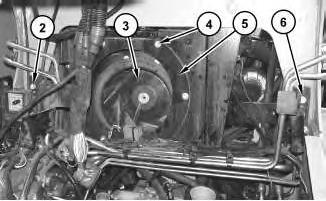
2. Remove bolts (4) and the washers. Remove seal (5) .
3. Remove fan assembly (3) .
4. Remove bolts (2) and the washers. Remove bolts (6) and the washers.

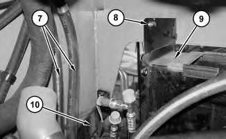
3
5. Remove nuts(8) and the washers. Remove shroud assembly (9) .
6. Disconnect hose assemblies(7) from bracket assembly (10) and remove bracket assembly (10) .
Installation Procedure
4
1. Position bracket assembly (10) to the machine and connect hose assemblies (7) to bracket assembly (10) .
2. Position shroud assembly (9) and install the washers and nuts (8) .
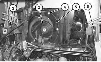
Illustration 5
3. Install the washers and bolts(6). Install the washers and bolts(2) .
4. Install fan assembly (3) .
5. Position seal (5) and install the washersand bolts (4) .
Note: Be sure that fan assembly (3) does not interfere with seal (5) through a complete revolution of fan assembly (3) .
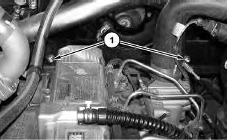
Illustration 6
6. Install the washers and bolts(1) .
End By:
a. Install the refrigerant condenser. Refer to Disassembly and Assembly, "Refrigerant CondenserRemove and Install".
b. Install the aftercooler. Refer to Disassembly and Assembly, "Aftercooler - Remove and Install".
c. Install the aftercooler fan motor. Refer to Disassembly and Assembly, "Gear Motor (Fan, Aftercooler) - Install".
Product: SKID STEER LOADER
Model: 272C SKID STEER LOADER RED
Configuration: 272C Skid Steer Loader RED00001-UP (MACHINE) POWERED BY 3044C Engine
Disassembly and Assembly
236B, 246B, 246C, 252B, 256C, 262B, 262C, 262C2 and 272C
Skid Steer Loaders Engine Supplement
Media Number -KENR5114-03
Publication Date -01/04/2011
Air Cleaner - Remove and Install
SMCS - 1051-010
Removal Procedure
Date Updated -19/04/2011
1. Tilt the radiator. Refer to Operation and Maintenance Manual, "Radiator Tilting".
1
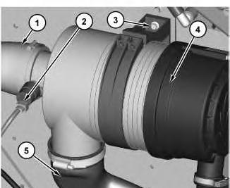
2. Disconnect harnessassembly (2). Disconnect hoses (1) and (5). Remove bolts (3) and air cleaner (4) .
Installation Procedure
1. Tilt the radiator. Refer to Operation and Maintenance Manual, "Radiator Tilting".
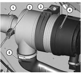
Illustration 2
g01340815
2. Position air cleaner (4) and install bolts (3). Connect hoses (1) and (5). Connect harness assembly (2) .
3. Tilt the radiator back to the original position. Refer to Operation and Maintenance Manual, "Radiator Tilting".
Copyright 1993 - 2020 Caterpillar Inc. All Rights Reserved. Private Network For SIS Licensees. Tue Sep 1 21:08:59 UTC+0530 2020
Product: SKID STEER LOADER
Model: 272C SKID STEER LOADER RED
Configuration: 272C Skid Steer Loader RED00001-UP (MACHINE) POWERED BY 3044C Engine
Disassembly and Assembly
236B, 246B, 246C, 252B, 256C, 262B, 262C, 262C2 and 272C
Skid Steer Loaders Engine Supplement
Media Number -KENR5114-03
Publication Date -01/04/2011
Alternator - Remove and Install
SMCS - 1405-010
S/N- DWS1-UP
S/N- JAY1-UP
S/N- MST1-UP
S/N- RED1-UP
S/N- TMW1-UP
Removal Procedure
Start By:
Date Updated -19/04/2011
A. Disconnect the battery. Refer to Disassembly and Assembly, "Battery and Battery Cable - Separate and Connect".
Note: Put identification marks on all hoses, on all hose assemblies, on all wires, and on all tube assemblies for installation purposes. Plug all hose assembliesand all tube assemblies. This helps to prevent fluid loss, and this helpsto keep contaminantsfrom entering the system.

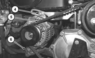
Illustration 1
2
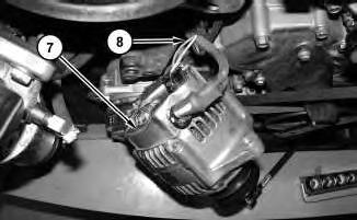
3
3. Position alternator (7) in order to accessharnessassembly (8) . Disconnect harness assembly (8) and remove alternator (7) .
Installation Procedure
Table 1
Required Tools
Tool Part Number Part Description Qty
A 155-0695 Thread Lock Compound 1
Illustration 4 g01336097

5
1. Position alternator (7) in order to allowaccess to connect harness assembly (8) . Connect harness assembly (8) .
2. Install alternator (7) . Install belt (5) . Install bolts (4) and (6) . Refer to Operation and Maintenance Manual, "Belt - Inspect/Adjust/Replace" for the proper belt tension.
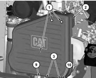
Illustration 6
3. Position cover (2) between the bracket assembly (9) and plate (10) . Apply Tooling (A) onto screws(1) and install screws (1) . Tighten screws (1) to a torque of 12 ± 3 N·m (9 ± 2 lb ft).
4. Apply Tooling (A) onto bolts (3) and install bolts (3) . Tighten bolts(3) to a torque of 15 ± 3 N·m (11 ± 2 lb ft).
End By: Connect the battery. Refer to Disassembly and Assembly, "Battery and Battery Cable - Separate and Connect". Copyright 1993 - 2020 Caterpillar Inc. All Rights Reserved. Private Network For SIS Licensees. Tue Sep 1 21:04:44 UTC+0530 2020
Product: SKID STEER LOADER
Model: 272C SKID STEER LOADER RED
Configuration: 272C Skid Steer Loader RED00001-UP (MACHINE) POWERED BY 3044C Engine
Disassembly and Assembly
236B, 246B, 246C, 252B, 256C, 262B, 262C, 262C2 and 272C
Skid Steer Loaders Engine Supplement
Media Number -KENR5114-03
Publication Date -01/04/2011
Battery and Battery Cable - Separate and Connect
SMCS - 1401-029-KA
S/N- DWS1-UP
S/N- JAY1-UP
S/N- MST1-UP
S/N- RED1-UP
S/N- TMW1-UP
Removal Procedure
Start By:
A. Tilt the cab. Refer to Disassembly and Assembly, "Cab - Tilt".
Date Updated -19/04/2011 i02636401
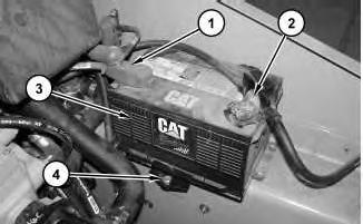
Illustration 1
1. Disconnect negative battery cable (2) .
2. Disconnect positive battery cable (1) .
3. Remove bolt (4) and the clamp. Remove battery (3). The weight of the battery is approximately 18 kg (40 lb).
Installation Procedure
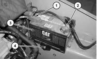
Illustration 2
g01321826
1. Install battery (3). The weight of the battery is approximately 18 kg (40 lb). Position the clamp and install bolt (4) .
2. Connect positive battery cable (1) .
3. Connect negative battery cable (2) .
End By: Lower the cab. Refer to Disassembly and Assembly, "Cab - Tilt".
Product: SKID STEER LOADER
Model: 272C SKID STEER LOADER RED
Configuration: 272C Skid Steer Loader RED00001-UP (MACHINE) POWERED BY 3044C Engine
Disassembly and Assembly
236B, 246B, 246C, 252B, 256C, 262B, 262C, 262C2 and 272C
Skid Steer Loaders Engine Supplement
Media Number -KENR5114-03
Cab - Tilt
SMCS - 7301-084
S/N- DWS1-UP
S/N- JAY1-UP
S/N- MST1-UP
S/N- RED1-UP
S/N- TMW1-UP
Raising the Cab
Publication Date -01/04/2011
Date Updated -19/04/2011
i02674905
Do not go beneath cab unlesscab isempty and support lever is engaged.
Failure to follow the instructionsor heed the warnings could result in injury or death.
Do not tilt the cab using an open door. The door must be closed and latched when lifting the cab. The door may become dislodged from its hinges and may cause serious personal injury or death.
1. Park the machine on level ground.
Note: Empty the water tank (if equipped) before you tilt the cab.
2. Lower the loader arms. If you tilt the cab upward with the loader lift arms in the RAISED position, you must engage the brace for the loader lift arms. See Operation and Maintenance Manual, "Loader Lift Arm Brace Operation" for the process for engaging the brace for the loader lift arms.
3. Release the hydraulic system pressure. Refer to Disassembly and Assembly, "Hydraulic System Pressure - Release".
4. Close the cab door and ensure that the door islatched.
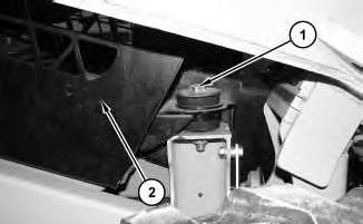
Illustration 1
5. Remove bolts (1) .
g01344027
Note: Note the location of the rubber mountsand the spacers for assembly purposes.
6. Raise cab (2) .
2 g01210136

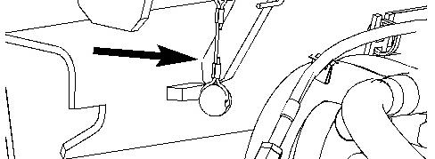
Illustration 3 g01210140
Cabsupportlever
7. Raise the cab until the cab support lever is in the ENGAGED position.
Lowering the Cab
Illustration 4 g01210140
Cabsupportlever
1. Raise the cab. With the help of another person, release the cab support lever.

5 g01344027
This is the sample of the manual
Click on the download link for complete Manual
2. Lower cab (2) .
3. Install bolts (1). Tighten bolts(1) to a torque of 125 ±10 N·m (92 ± 7 lb ft).
Copyright 1993 - 2020 Caterpillar Inc. All Rights Reserved. Private Network For SIS Licensees. Tue Sep 1 21:10:00 UTC+0530 2020