

Product: SKID STEER LOADER
Model: 268B SKID STEER LOADER LBA
Configuration: 248B 268B SKID STEER LOADER LBA00001-UP (MACHINE) POWERED BY 3044C Engine
Disassembly and Assembly
3044C Industrial Engine and Engines for Caterpillar Built Machines Media
Bearing Clearance - Check
SMCS - 1203-535; 1219-535
Measurement Procedure Table 1
Required Tools
Plastic Gauge (Green)
to
Plastic Gauge (Red)
to 0.152 mm (0.002 to 0.006 inch)
Plastic Gauge (Blue) 0.102 to 0.229 mm (0.004 to 0.009 inch)
Plastic Gauge (Yellow) 0.230 to 0.510 mm (0.009 to 0.020 inch)
Note: Plastic gauge may not be necessary when the engine is in the chassis.
NOTICE
Keep all parts clean from contaminants.
Contaminants may cause rapid wear and shortened component life.
i05977048
Note: Cat does not recommend the checking of the actual bearing clearances particularly on small engines. This is because of the possibility of obtaining inaccurate results and the possibility of damaging the bearing or the journal surfaces. Each Cat engine bearing is quality checked for specific wall thickness.
Note: The measurements should be within specifications and the correct bearings should be used. If the crankshaft journals and the bores for the block and the rods were measured during disassembly, no further checks are necessary. However, if the technician still wants to measure the bearing clearances, Tooling (A) is an acceptable method. Tooling (A) is less accurate on journals with small diameters if clearances are less than 0.10 mm (0.004 inch).
NOTICE
Lead wire, shim stock or a dial bore gauge can damage the bearing surfaces.
The technician must be very careful to use Tooling (A) correctly. The following points must be remembered:
• Ensure that the backs of the bearings and the bores are clean and dry.
• Ensure that the bearing locking tabs are properly seated in the tab grooves.
• The crankshaft must be free of oil at the contact points of Tooling (A).
1. Put a piece of Tooling (A) on the crown of the bearing that is in the cap.
Note: Do not allow Tooling (A) to extend over the edge of the bearing.
2. Use the correct torque-turn specifications in order to install the bearing cap. Do not use an impact wrench. Be careful not to dislodge the bearing when the cap is installed.
Note: Do not turn the crankshaft when Tooling (A) is installed.
3. Carefully remove the cap, but do not remove Tooling (A). Measure the width of Tooling (A) while Tooling (A) is in the bearing cap or on the crankshaft journal. Refer to Illustration 1.
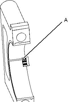

Illustration 1 g01152855
Typical Example
4. Remove all of Tooling (A) before you install the bearing cap.
Note: When Tooling (A) is used, the readings can sometimes be unclear. For example, all parts of Tooling (A) are not the same width. Measure the major width in order to ensure that the parts are within the specification range. Refer to Specifications Manual, "Connecting Rod Bearing Journal" and Specifications Manual, "Main Bearing Journal" for the correct clearances. Copyright 1993 - 2019 Caterpillar Inc. All Rights Reserved.
Product: SKID STEER LOADER
Model: 268B SKID STEER LOADER LBA
Configuration: 248B 268B SKID STEER LOADER LBA00001-UP (MACHINE) POWERED BY 3044C Engine
Disassembly and Assembly
3044C Industrial Engine and Engines for Caterpillar Built Machines
Media Number -RENR7582-07 Publication Date -01/01/2010 Date Updated -26/02/2010
Camshaft - Remove and Install
SMCS - 1210-010
Removal Procedure
Start By:
A. Remove the rocker shaft and pushrods. Refer to Disassembly and Assembly, "Rocker Shaft and Pushrod - Remove".
B. Remove the front housing. Refer to Disassembly and Assembly, "Housing (Front)Remove".
NOTICE
Keep all parts clean from contaminants.
Contaminants may cause rapid wear and shortened component life.
1. Turn the engine upside-down so the valve lifters are held in a position away from the camshaft.
This is the sample of the manual
Click on the download link for complete Manual
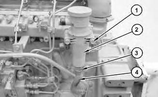
1
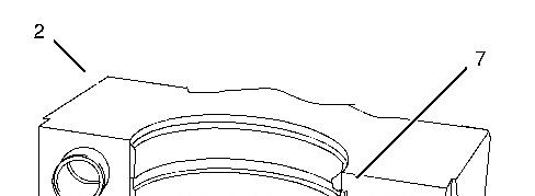
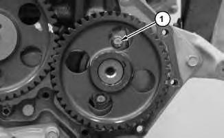
2. Remove bolts (1) .
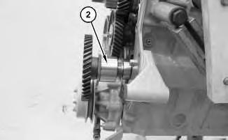
Illustration 2
NOTICE
Do not damage the lobes or the bearings when the camshaft is removed or installed.
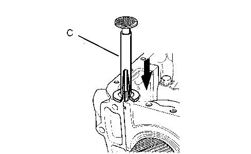
3. Carefully remove camshaft (2) .
Installation Procedure
NOTICE
Keep all parts clean from contaminants.
Contaminants may cause rapid wear and shortened component life.
1. Ensure that the camshaft is clean. Lubricate the camshaft with clean engine oil prior to installation.
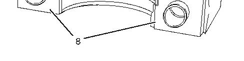
Illustration 3
NOTICE
Do not damage the lobes or the bearings when the camshaft is removed or installed.
2. Carefully install camshaft (2) .
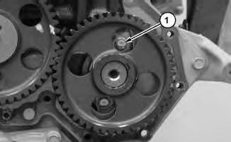
Illustration 4
3. Install bolts (1). Tighten bolts (1) to a torque of 10 to 13 N·m (7 to 10 lb ft).
End By:
a. Install the front housing. Refer to Disassembly and Assembly, "Housing (Front) - Install".
b. Install the rocker shaft and pushrods. Refer to Disassembly and Assembly, "Rocker Shaft and Pushrod - Install". Copyright 1993 - 2019 Caterpillar Inc.
Network For SIS Licensees. Fri Dec 20 09:36:13 UTC+0530 2019
Product: SKID STEER LOADER
Model: 268B SKID STEER LOADER LBA
Configuration: 248B 268B SKID STEER LOADER LBA00001-UP (MACHINE) POWERED BY 3044C Engine
Disassembly and Assembly
3044C Industrial Engine and Engines for Caterpillar Built Machines
i03702890
Camshaft Gear - Remove and Install
SMCS - 1210-010-GE
Removal Procedure Table 1
Required Tools
Start By:
A. Remove the camshaft. Refer to Disassembly and Assembly, "Camshaft - Remove and Install".
NOTICE
Keep all parts clean from contaminants.
Contaminants may cause rapid wear and shortened component life.
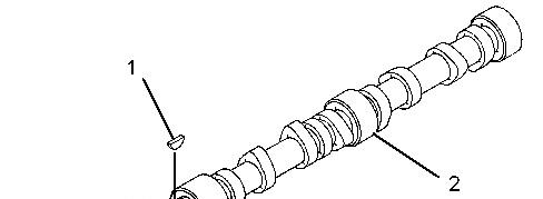

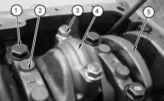
Illustration 1 g01993021
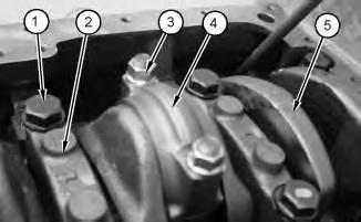
1. Use Tooling (A) to remove camshaft gear (4) from camshaft (2) . Remove key (1) and thrust plate (3) .
Note: Do not lose the key from the camshaft gear.
Installation Procedure NOTICE
Keep all parts clean from contaminants.
Contaminants may cause rapid wear and shortened component life.
1. Inspect the camshaft gear, the key, and the thrust plate for wear or damage.
Illustration 2 g01993021
2. Install key (1) and thrust plate (3) . Raise the temperature of camshaft gear (4) and install camshaft gear (4) on camshaft (2) .
Note: Ensure that the key is installed on the camshaft. When you install the camshaft gear, ensure that the marked teeth are facing toward the front. If necessary, tap the gear with a soft hammer in order to seat the key in the keyway.
End By: Install the camshaft. Refer to Disassembly and Assembly, "Camshaft - Remove and Install".
1993 - 2019 Caterpillar Inc.
Product: SKID STEER LOADER
Model: 268B SKID STEER LOADER LBA
Configuration: 248B 268B SKID STEER LOADER LBA00001-UP (MACHINE) POWERED BY 3044C Engine
Disassembly and Assembly
3044C Industrial Engine and Engines for Caterpillar Built Machines
Media Number -RENR7582-07 Publication Date -01/01/2010 Date Updated -26/02/2010
Connecting Rod Bearings - Install
SMCS - 1219-012
Installation Procedure NOTICE
Keep all parts clean from contaminants.
Contaminants may cause rapid wear and shortened component life.
i01996564
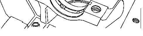
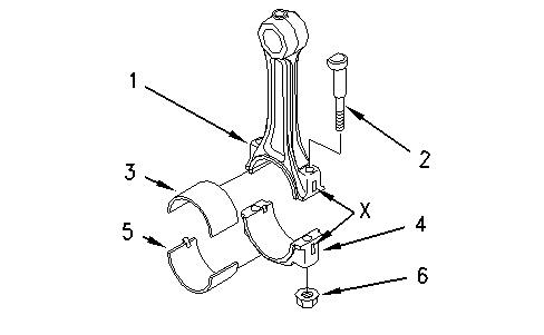
1. Install upper connecting rod bearing (3) in connecting rod (1). The upper connecting rod bearing must be centered in the connecting rod. Lubricate the bearing face with clean engine oil.
2. Pull connecting rod (1) into position against the crankshaft.
3. Install lower connecting rod bearing (5) in connecting rod cap (4). The lower connecting rod bearing must be centered in the connecting rod cap. Lubricate the bearing face with clean engine oil.
Note: Do not mix the connecting rod caps and the connecting rods.
4. Install connecting rod cap (4) .
Note: The connecting rod and the connecting rod cap should have matching Numbers (X) on the side. Ensure that the marks are on the same side.
5. Install nuts (6) on connecting rod bolts (2). Tighten the nuts evenly to a torque of 49 to 59 N·m (36 to 44 lb ft).
6. Repeat Steps 1 through 5 for the remaining connecting rod bearings.
7. Rotate the crankshaft in order to ensure that there is no binding.
End By: Install the engine oil pan. Refer to Disassembly and Assembly, "Engine Oil PanRemove and Install".
1993 - 2019 Caterpillar Inc.
Dec 20 09:38:55 UTC+0530 2019
Product: SKID STEER LOADER
Model: 268B SKID STEER LOADER LBA
Configuration: 248B 268B SKID STEER LOADER LBA00001-UP (MACHINE) POWERED BY 3044C Engine
Disassembly and Assembly
3044C Industrial Engine and Engines for Caterpillar Built Machines
Media Number -RENR7582-07 Publication Date -01/01/2010 Date Updated -26/02/2010
Connecting Rod Bearings - Remove
SMCS - 1219-011
Removal Procedure
Start By:
A. Remove the engine oil pan. Refer to Disassembly and Assembly, "Engine Oil Pan - Remove and Install".
NOTICE
Keep all parts clean from contaminants.
Contaminants may cause rapid wear and shortened component life.
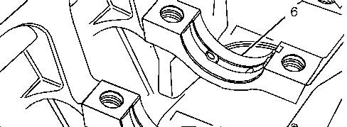
1. In order to remove the connecting rod caps, rotate the crankshaft in a clockwise direction until the piston is at the bottom center position.
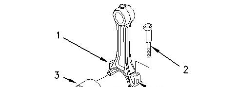

Illustration 1 g01001625
2. Inspect connecting rod (1) and connecting rod cap (4) for the proper identification mark. Note: The connecting rod and the connecting rod cap should have matching Numbers (X) on the side. Mark the connecting rod and the connecting rod cap, if necessary.
3. Remove nuts (6) from connecting rod bolts (2). Remove connecting rod cap (4). Remove lower connecting rod bearing (5) from connecting rod cap (4) .
4. Carefully push connecting rod (1) into the cylinder bore. Remove upper connecting rod bearing (3) from connecting rod (1) .
5. Repeat Steps 1 through 4 for the remaining connecting rod bearings.
1993 - 2019 Caterpillar Inc.
Fri Dec 20 09:38:37 UTC+0530 2019
Product: SKID STEER LOADER
Model: 268B SKID STEER LOADER LBA
Configuration: 248B 268B SKID STEER LOADER LBA00001-UP (MACHINE) POWERED BY 3044C Engine
Disassembly and Assembly
3044C Industrial Engine and Engines for Caterpillar Built Machines
Media Number -RENR7582-07 Publication Date -01/01/2010 Date Updated -26/02/2010
Crankcase Breather - Remove and Install
SMCS - 1317-010
Removal Procedure NOTICE
Keep all parts clean from contaminants.
Contaminants may cause rapid wear and shortened component life.

i02001086