

Product: SKID STEER LOADER
Model: 262C2 SKID STEER LOADER TMW
Configuration: 262C2 Skid Steer Loader TMW00001-UP (MACHINE) POWERED BY C3.4 Engine
Disassembly and Assembly
236B, 246B, 246C, 252B, 256C, 262B, 262C, 262C2 and 272C
Skid Steer Loaders Engine Supplement
Media Number -KENR5114-03
Engine - Install
SMCS - 1000-012
S/N - RED1-UP
S/N - TMW1-UP
Installation Procedure
Table 1
NOTICE
Care must be taken to ensure that fluids are contained during performance of inspection, maintenance, testing, adjusting and repair of the product. Be prepared to collect the fluid with suitable containers before opening any compartment or disassembling any component containing fluids.
Refer to Special Publication, NENG2500, "Caterpillar Dealer Service Tool Catalog" for tools and supplies suitable to collect and contain fluids on Caterpillar products.
Dispose of all fluids according to local regulations and mandates.
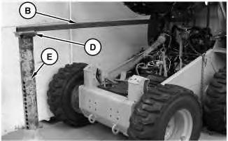
1. Install trolley (C) onto tube assembly (B). Attach tube assembly (B) to the machine. Tube assembly (B) will attach to the machine at the location of the bracket for the hydraulic tank. Position the other end of tube assembly (B) and base (D) onto Tooling (E) .
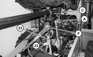
2. Attach Tooling (A) to trolley (C) and to piston pump (22). Attach Tooling (F) to tube assembly (B) and to gear pump (23). The combined weight of the pumps is approximately 118 kg (260 lb). Apply a slight lifting tension.
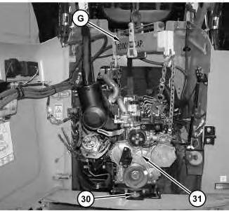
3. Attach Tooling (G) and a suitable lifting device to engine (31). The weight of engine (31) is approximately 340 kg (750 lb).
4. Use Tooling (G) and the suitable lifting device in order to position engine (31) into the machine.
Note: Ensure that the splines for the pump drive coupling and the pumps are aligned.
5. A nylon rod is assembled into the mounting bracket. The rod will prevent the mounting bolts from turning when the nuts are tightened.
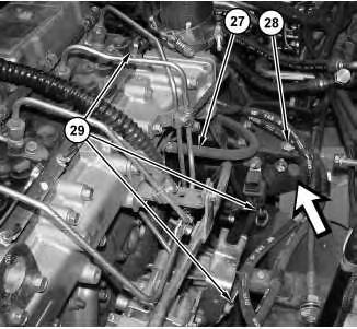
6. Install bolts (28) and nuts to each side of engine (31) .
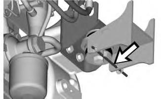
7. Install bolt (30). Tighten bolt (30) to a torque of 90 ± 10 N·m (66 ± 7 lb ft).
8. Connect harness assemblies (29) .
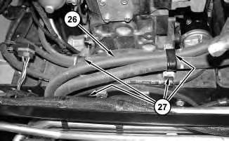
9. Connect hose (27) .
6
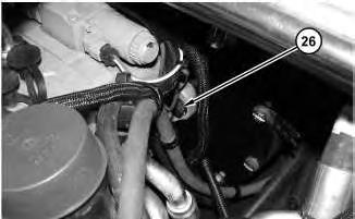
10. Install pump mounting bolts (26).
11. Remove all of the Tooling that was used to support the pumps.
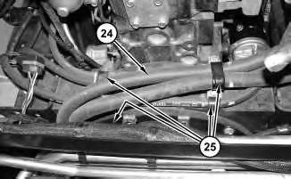
12. Position hoses (24). Install all clamps (25) that are securing hoses (24) to the engine.

8
13. Install bracket (21) .
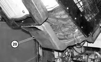
Illustration 9
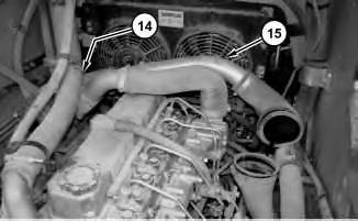
14. Install duct (20) .

Illustration 10
15. Connect hose (19) .
g01343110
16. Connect cable assembly (16) and install clip (18). Tighten nut (17) .
17. Connect clips (15) .
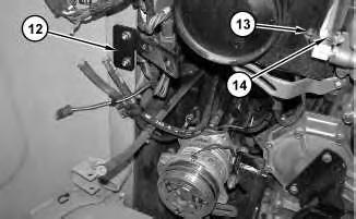
Illustration 11
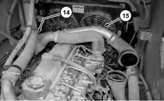
18. Connect hose (14) .
19. Connect harness assembly (13) .
20. Install bracket (12) .
g01343105
This is the sample of the manual
Click on the download link for complete Manual
12
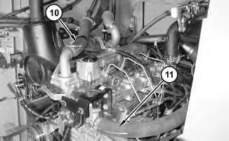
21. Connect hoses (10) and (11) .
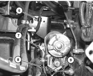
Illustration 13
22. Connect harness assemblies (9) .
23. Connect cable assemblies (8) .
24. Connect cable assembly (7) .
25. Connect clip (6) .
14
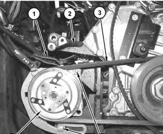
26. Position air conditioner compressor (4). Install belt (3) and install bolts (5). Refer to Operation and Maintenance Manual, "Belts - Inspect/Adjust/Replace".
27. Install alternator bracket (2). Tighten the bolts that hold alternator (2) to a torque of 13 N·m (115 lb in).
28. Connect harness assembly (1) .
End By:
a. Install the aftercooler and mounting. Refer to Disassembly and Assembly, "Aftercooler Fan and Mounting - Remove and Install".
b. Install the radiator. Refer to Disassembly and Assembly, "Radiator and Hydraulic Oil Cooler - Install".
c. Install the alternator. Refer to Disassembly and Assembly, "Alternator - Remove and Install".
d. Install the air cleaner. Refer to Disassembly and Assembly, "Air Cleaner - Remove and Install".
e. Install the fuel priming pump and primary filter. Refer to Disassembly and Assembly, "Fuel Priming Pump and Primary Filter (Water Separator) - Remove and Install".
f. Connect the battery. Refer to Disassembly and Assembly, "Battery and Battery CableSeparate and Connect".
Product: SKID STEER LOADER
Model: 262C2 SKID STEER LOADER TMW
Configuration: 262C2 Skid Steer Loader TMW00001-UP (MACHINE) POWERED BY C3.4 Engine
Disassembly and Assembly
236B, 246B, 246C, 252B, 256C, 262B, 262C, 262C2 and 272C
Skid Steer Loaders Engine Supplement
Media Number -KENR5114-03
Engine - Install
SMCS - 1000-012
S/N - DWS1-UP
S/N - JAY1-UP
S/N - MST1-UP
S/N - RED1-UP
S/N - TMW1-UP
Installation Procedure
1
A 1U-9200 Lever Puller Hoist 1
B 138-7575 Link Bracket 4
C 368-0005 C-Frame Assembly 1
D 138-7573 Link Bracket 1
i04351954
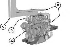
Illustration 1
Typical Example of Tooling (C) .
g02024556
1. Attach Tooling (B) , Tooling (C) , Tooling (D) , and a suitable lifting device to engine (32) . The weight of engine (34) is approximately 340 kg (750 lb).
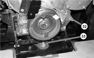
Illustration 2
g02024435
2. Position engine (32) in the machine. Install bolt (33) . Tighten bolt (33) to a torque of 90 ± 10 N·m (66 ± 7 lb ft).
3
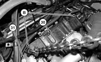
3. Install nuts (31) . Remove Tooling (B) from housing (30) .
Note: Nylon rods are installed at the factory in order to support the bolts for nuts (31) during the installation process.
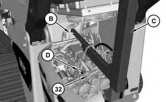
Illustration 4
Typical Example of Tooling (C) .
4. Remove Tooling (B) , Tooling (C) , Tooling (D) , and the suitable lifting device from engine (32) .
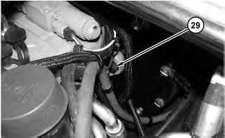
Illustration 5
5. Install bolts (29) .
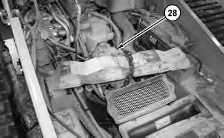
Illustration 6
7
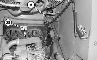
6. Remove the suitable cribbing and the suitable lifting device from pumps (28) . Remove Tooling (A) from pumps (28) .
8
7. Position hoses (26) . Install all clamps (27) that secure hoses (26) to the engine.
9
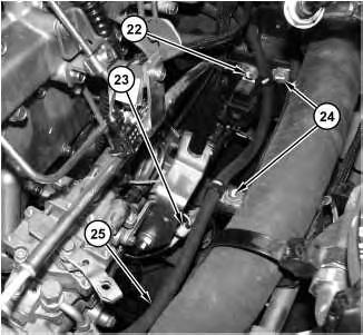
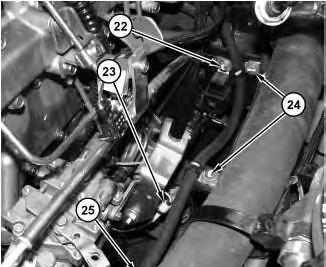
8. Connect hose (25) . Install bolts (22) and (24) .
9. Connect harness assembly (23) . Install all mounting hardware that retains harness assembly (23) to the engine.
12
12. Install tube assembly (15) and tighten hose clamp (14) .

Illustration 13
13. Connect hoses (12) and install bolts (13) .
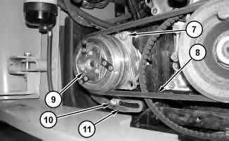
Illustration 14
14. Position refrigerant compressor (9) . Install bracket (11) , bolts (10) , belt (8) , and nut (7) . Refer to Operation and Maintenance Manual, "Belts - Inspect/Replace" for the proper belt tension.
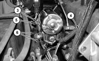
Illustration 15
g01367020
15. Connect cable assembly (5) and install nut (3) . Connect harness assembly (4) and cable assemblies (6) . Install all mounting hardware.
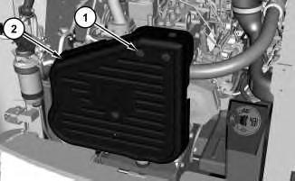
Illustration 16
16. Install guard (2) and bolts (1) .
End By:
g02023198
a. Tilt the cab. Refer to Disassembly and Assembly, "Cab - Tilt".
b. Remove the muffler. Refer to Disassembly and Assembly, "Muffler - Remove and Install".
c. Install the air cleaner. Refer to Disassembly and Assembly, "Air Cleaner - Remove and Install".
Wed Oct 27 21:19:06 UTC+0530 2021
Product: SKID STEER LOADER
Model: 262C2 SKID STEER LOADER TMW
Configuration: 262C2 Skid Steer Loader TMW00001-UP (MACHINE) POWERED BY C3.4 Engine
Disassembly and Assembly
236B, 246B, 246C, 252B, 256C, 262B, 262C, 262C2 and 272C
Skid Steer Loaders Engine Supplement
Media Number -KENR5114-03
Pump Mounting - Remove and Install
SMCS - 3203-010-MT; 5062-010; 5070-010-MT
S/N - DWS1-UP
S/N - JAY1-UP
S/N - MST1-UP
S/N - RED1-UP
S/N - TMW1-UP
Removal Procedure
Start By:
a. Remove the engine. Refer to Disassembly and Assembly, "Engine - Remove".
i06648889
Illustration 1
g01342637
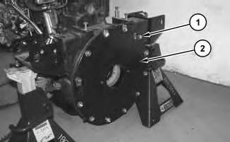
1. Remove bolts (1). Remove adapter plate (2).

Illustration 2
g03844324
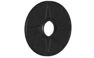
Illustration 3
Pump side of nylon flange (4).
g03844331

Illustration 4
Engine side of nylon flange (4).
g03844336
Note: Note the orientation of flange for installation.
2. Remove bolts (3). Remove nylon flange (4).
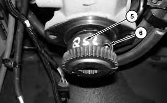
Illustration 5
3. Loosen bolt (6). Remove hub (5).
Installation Procedure
Table 1
Required Tools
g01342642
Tool Part Number Part Description Qty
A 9S-3263 Thread Lock Compound 1
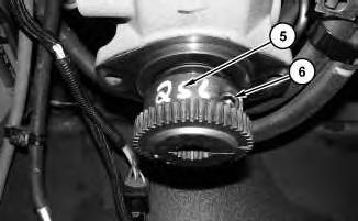
Illustration 6
g01342642
1. Apply Tooling (A) to bolt (6). Install hub (5). Tighten bolt (6) to a torque of 102 ± 5 N·m (75 ± 4 lb ft).
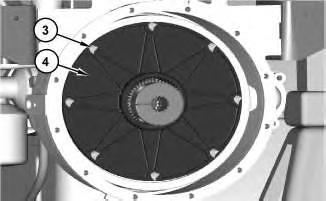
Illustration 7
g03844324
Note: Refer to note in removal procedure as to orientation of flange.
2. Install nylon flange (4). Install bolts (3).
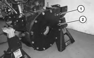
Illustration 8
3. Install adapter plate (2). Install bolts (1).
g01342637
End By:
a. Install the engine. Refer to Disassembly and Assembly, "Engine - Install".
Copyright 1993 - 2021 Caterpillar Inc. All Rights Reserved. Private Network For SIS Licensees. Wed Oct 27 21:18:52 UTC+0530 2021
Product: SKID STEER LOADER
Model: 262C2 SKID STEER LOADER TMW
Configuration: 262C2 Skid Steer Loader TMW00001-UP (MACHINE) POWERED BY C3.4 Engine
Disassembly and Assembly
236B, 246B, 246C, 252B, 256C, 262B, 262C, 262C2 and 272C
Skid Steer Loaders Engine Supplement
Media Number -KENR5114-03
Engine - Remove
SMCS - 1000-011
S/N - DWS1-UP
S/N - JAY1-UP
S/N - MST1-UP
S/N - RED1-UP
S/N - TMW1-UP
Removal Procedure
Table 1
Required Tools
A 1U-9200 Lever Puller Hoist 1
B 138-7575 Link Bracket 4
C 368-0005 C-Frame Assembly 1
D 138-7573 Link Bracket 1
Start By:
i04351955
A. Remove the air cleaner. Refer to Disassembly and Assembly, "Air Cleaner - Remove and Install".
B. Remove the muffler. Refer to Disassembly and Assembly, "Muffler - Remove and Install".
C. Tilt the cab. Refer to Disassembly and Assembly, "Cab - Tilt".
1
1. Remove bolts (1) and guard (2) .
Illustration 2
2. Disconnect harness assembly (4) and cable assemblies (6) . Remove all mounting hardware. Remove nut (3) and disconnect cable assembly (5) .
3
3. Remove nut (7) , bolts (10) , belt (8) , and bracket (11) . Position refrigerant compressor (9) out of the way.
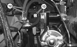
Illustration 4
g01367022
4. Disconnect hoses (12) and remove bolts (13) .
5 g02023232
5. Loosen hose clamp (14) and remove tube assembly (15) .
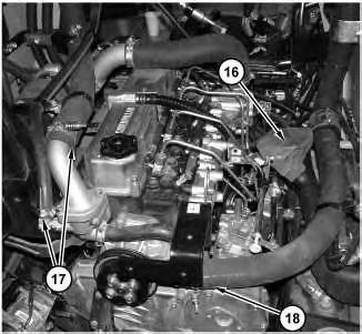
Illustration 6
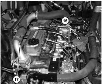
6. Disconnect hoses (17) and (18) . Remove duct (16) .
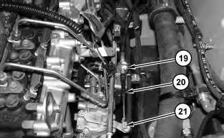
Illustration 7
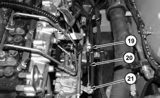
7. Loosen nut (19) . Remove pin assembly (21) and disconnect cable assembly (20) .
8
8. Disconnect harness assembly (23) . Remove all mounting hardware that is retaining harness assembly (23) to the engine.
9. Remove bolts (22) and (24) . Disconnect hose (25) .
Illustration 9
10. Remove all clamps (27) that are securing hoses (26) to the engine. Position hoses (26) out of the way.
This is the sample of the manual
Click on the download link for complete Manual
10
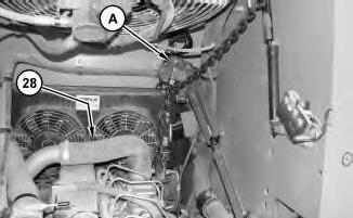
Illustration 11
11. Support pumps (28) with suitable cribbing and a suitable lifting device. Support pumps (28) with Tooling (A) .
12
12. Remove bolts (29) .