

Previous Screen
Product: MOTOR GRADER
Model: 24M MOTOR GRADER B93
Configuration: 24M Motor Grader B9300001-UP (MACHINE) POWERED BY C18 Engine
Troubleshooting
Cat® Grade Control Cross Slope System for Motor Graders
Media Number -M0068530-00
Publication Date -01/06/2016 Date Updated -29/06/2016
Symptom Troubleshooting
i06676145
SMCS - 1250; 1400-035; 3000-035; 4000-035; 4800-035; 4810-035; 5000-035; 5050-035; 7000035; 7008-035; 7569-035; 7569; 7600-035; 775E-035
Use the following practices and general knowledge as a guideline to troubleshoot the system:
Know the Machine
Understand the operation of the machine. Know if the symptom is a characteristic of normal operation or if the symptom is a failure.
Read the systems operation information to understand the systems of the machine. Understand the interaction of the machine systems.
Understand the Symptom
Speak with the operator about the symptom. Acquire the following Information:
• The performance of the machine prior to the failure
• First occurrence of the symptom
• The operating conditions at the time of the failure
• The sequence of events prior to the failure (order of the occurrences)
• The troubleshooting steps that have been taken
• The history of repairs of the machine
• The preventive maintenance of the machine
• Related service information about current problems that affect the serial number of the machine
• Perform visual check of the Cross Slope System (sensors harness, connectors).
Verify the Symptom
When possible, attempt to duplicate the symptom. Operate the machine and repeat the conditions that caused the failure. Check the gauges inside the cab. Notice any unusual odors in the cab. Listen for unusual noises.
Determine if the ECM has detected any faults. A diagnostic code is used to specify each detected fault.
Determine Possible Causes
Use the information from the operator and your inspection. Attempt to identify a common cause if there is more than one symptom.
If you troubleshoot diagnostic codes and the problem is not resolved, continue troubleshooting using the "Symptom Troubleshooting" section of this manual. Identify the component that is the most probable cause of the symptom.
Test and Repair the System
Use the tests and procedures in this manual to verify the cause of the symptom. Once the cause has been identified, repair the failure. Then, test the system again to verify that the symptom is resolved.
Provide Feedback to Caterpillar
Share your troubleshooting information. After the correct repair has been performed, use the form in "SIS" or "CBT" feedback to write a brief description about the symptom, testing, and repair of the machine. Include your phone number or your e-mail address so that you can be contacted. This feedback information helps Caterpillar improve service information.
Copyright 1993 - 2025 Caterpillar Inc. All Rights Reserved.
Network For SIS Licensees. Tue May 13 00:48:12 UTC+0530 2025
Previous Screen
Product: MOTOR GRADER
Model: 24M MOTOR GRADER B93
Configuration: 24M Motor Grader B9300001-UP (MACHINE) POWERED BY C18 Engine
Troubleshooting
Cat® Grade Control Cross Slope System for Motor Graders
-M0068530-00
Operational Problems
SMCS - 7220-035
Operational practice for the best accuracy
Follow the below practices for best accuracy and smooth grade flow:
• Run the machine smoothly without any abrupt starts or stops.
• If operating on a rough surface, drive slow enough to prevent tire bounce.
-29/06/2016
i06676188
• Operating at slower speeds provides more precise cross slope control. Experimentation may be necessary to find the right speed at your site.
• Operate with no wheel lean, articulation, blade cushion feature, or circle side shift. These conditions will cause cross slope error.
Note: The blade cushion feature will affect the quality of the grade, when it is enabled.
• Maintain the proper and correct tiers pressure, refer to the manufacturing specification and maintenance manual of the machine.
• Calibrate the Cross Slope system properly if needed, ensure that there is no active (FMI13) failure mode of any of the Cross Slope Sensors (system out of calibration).
Refer to Calibration section of this document for more details.
Note: The inactive automatic control state may occur when the operator attempts to enable the automatic controls by pressing and releasing the auto/manual switch. The auto icon will flash at a rate of times two per second which indicate inactive automatic state (Cross Slope System control temporary unavailable).
Condition for the Cat Grade Control Cross Slope System to be operational
Before operating the Cross Slope sensor, check that the following conditions is true:
• Operator is seated.
Note: The implement ECM monitors the input of the machine seat switch and implement will disable the cross slope system, if the operator is not seated
• Engine is running.
• Parking break is disengaged.
• Implement lock switch is disabled.
Note: Implement ECM monitors the implement lock out switch output, if the lock out switch is enabled the Cross Slope System will be disabled.
• Display must be in one of the two cross slope screens.
• No active diagnostic on a required input or output is present.
• System has no active codes or events.
Refer to Diagnostic Trouble Codes section of this document if any code or event is active.
Operation problems
Unstable grade
The factors which affect the quality of the grade are given below:
• Soil Type
• Machine Speed
• Amount of cut
The operator can accomplish the desired grade by adjusting the valve speed (by slowing or speeding up the response of the automatic control system). By adjusting the valve speed, the operator can overcome the three factors that are listed above.
This is the sample of the manual
Click on the download link for complete Manual
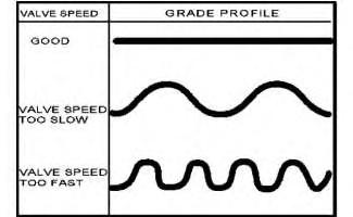
Illustration 1
Grade profile
The unstable grade may be a result of improper blade reaction time of the valve speed. Unstable grade may cause short waves in the materials, if the valve speed is too high (over correcting the blade movements) or long rolling waves in the materials, if the valve speed is too slow (not correcting the blade movement fast enough) as shown in Illustration 1.
Blade reaction time adjustment
Use the machine display "valve speed" menu to adjust the response time of the valve to reach the desire grade. Decrease the valve speed if the Cross Slope is over correcting (short wave in the material). Increase the valve speed if the valve speed is too slow or not correcting fast enough (long rolling material or grades). Refer to Illustration 1. The procedure to adjust the valve speed on the different types of display are explained below:
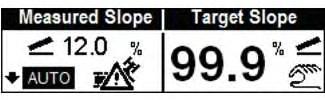
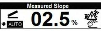
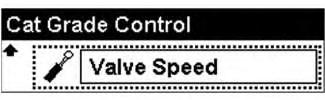
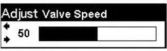
Illustration 5
g06067819
Go to "performance screen" menu, select "cross slope" > "Target slope" > press the arrow down or up, select "valve speed" adjust the valve speed. Refer Illustration 2, Illustration 3, Illustration 4, and Illustration 5.

Illustration 6
g06067824
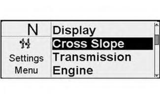
Illustration 7
g06067826
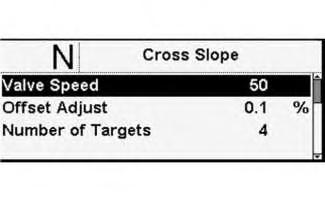
Illustration 8
g06067829
Go to "setting menu 2", select "Cross Slope" > "valve speed" > adjust the valve speed. Illustration 6, Illustration 7, and Illustration 8.
9 g06067833
Illustration 10 g06067842

Illustration 11 g06067846
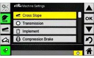
Go to "machine menu" > "machine setting" > "cross slope" > "valve speed" > used the increment/decrement bar to adjust the valve speed percentage. Press the (+) button on the right end of the bar to increase the percentage. Press the (-) button on the left end of the bar to decrease the percentage. Refer to Illustration 9, Illustration 10, Illustration 11.
Note: The number will appear in yellow text while setting. The newly set number will appear in white text. Press "ok" button to set and the "back" button to return to the pervious menu.
Refer to media System Operation Troubleshooting Testing and Adjusting, UENR5919, "16M3 and 18M3 Motor Graders Information Display" for step by step procedure on how to adjust the valve speed on the machine display.
Note: The Valve Speed setting is used to adjust the responsiveness of the Cross Slope System when controlling the blade. A higher value will cause the system to react faster. A lower number will cause the system to react slower.
Grade accuracy
The probable causes for the failure of grade accuracy are given below:
Blade
An accuracy problems or uneven grade could be the result of excessive wear to the cutting edge of the Blade.
To check the cutting edge of the blade for excessive wear or uneven edges. Use a string line, by running it from one end of the blade tip to the other end, you can tell if the cutting edges are uneven. The string should be relatively level with the cutting edge. Check the moldboard for straightness. The line of bolts that hold the cutting edge to the blade or moldboard should be straight.
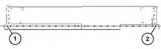
Illustration 12
(1) Outermost hole
(2) Outermost hole
g06069744
Run a string line across the moldboard holes. The string line should go from Point (1) to Point (2) or the two outermost holes. The tolerance for the holes is 1.8 mm (0.07 inch), above or below the center line.
Shims
Excessive play of the blade and circle could cause an accuracy problems or uneven grade. Check the blade and circle for worn shims. Replace the worn shims.
Refer to the System Operation Troubleshooting Testing and Adjusting, UENR1797, "Cat® Grade Control Cross Slope for Motor Graders".
Cross Slope System Sensors out of calibration
Visually inspect the sensors to ensure that all the bolts used to secure the Cross Slope System sensors are in place and the sensors are secured to the mounting brackets.
Cutting and rewelding or relocating the Blade rotation sensor bracket may cause accuracy issues.
Realign the Cross Slope System sensor that was not secured or relocated. Secure the Cross Slope System sensor to the machine bracket and perform sensor calibration, refer to the Testing and Adjusting manual for more details. Copyright 1993 - 2025 Caterpillar Inc.
Previous Screen
Product: MOTOR GRADER
Model: 24M MOTOR GRADER B93
Configuration: 24M Motor Grader B9300001-UP (MACHINE) POWERED BY C18 Engine
Troubleshooting
Cat® Grade Control Cross Slope System for Motor Graders
Media Number -M0068530-00
Determining Diagnostic Trouble Codes
SMCS - 0785-UE; 7490; 7569
The following are the diagnostic codes for the Cat® Grade control Cross Slope System:
CID - Component Identifier
FMI - Failure Mode Identifier
WCI - Warning Category Identifier
Warning Level
-29/06/2016
i06684353
The ECM will assign warning level to an active code. The warning level is based on the severity of the abnormal system condition. Each warning level requires a specific response from the operator. The warning levels and required operator response are listed below:
Level 1
Warning level one alert the operator that a machine system requires attention. The operator should check the involved system condition or perform maintenance on the involved system at earliest possible time.
Level 2
Warning level two requires changing the operation of the machine or preforming maintenance procedure. Failure to correct the problem that causes this warning, may damage the components from the machine system that are involved.
Level 2S
Warning level 2S requires an immediate change in machine operation to avoid possible damage to the system of the machine.
Level 3
Warning level 3 requires an immediate safe shutdown of the machine to avoid damage to the machine or injury to personal around the machine. Problem that causes the event must be corrected before machine operation can resume.
Cat® Grade Control Cross Slope System Codes
Table 1
Diagnostic Code List
Inclination sensor power supply
Refer to Systems Operation, Troubleshooting, Testing and Adjusting, KENR9041, "120M Series 2, 120M2, 12M Series 2, 12M Series II, 140M Series 2 and 160M Series 2 Motor Graders Implement Electronic Control System" for more information on diagnostic codes.
Failure Mode Identifier (FMI) General Description
There are five different failure mode identifiers related to the cross slope system FMI 2, 3, 4, 9, and 13.
FMI 02 - Data erratic, intermittent, or incorrect
The signal from a component is present. The control ECM that reads the diagnostic information cannot read the signal properly. The signal appears to be gone, unstable, or invalid. The data can be correct or incorrect intermittently. Also, this condition relates to communication between ECM controls. This is an example of communication between controls. When the monitoring system is looking for the engine speed from the Engine ECM over the Cat® Data Link. Some of the conditions that cause the FMI 02 diagnostic code to be activated are:
• There is a poor connection in the circuit.
• The signal is intermittent or erratic.
• The signal is receiving interference from another circuit.
• An ECM has failed. This is unlikely.
FMI 03 - Voltage above normal
The component or system voltage is higher than the limit. An FMI 03 most often relates to a signal circuit. Some of the conditions that cause an FMI 03 diagnostic code to be activated are listed below:
• Power supply failure
• An open circuit or a bad connection
• A short to another voltage source
• The sensor or the switch has failed
• An ECM has failed. This is unlikely
FMI 04 - Voltage below Normal
The component or system voltage is lower than the limit. An FMI 04 diagnostic code most often relates to a power supply circuit. Some of the conditions that could cause an FMI 04 diagnostic code are listed below:
• The circuit is shorted to a ground source.
• The circuit is open or has a poor connection.
• The ground circuit has failed.
• A component has failed.
• An ECM has failed. This is unlikely.
FMI 09 - Abnormal Update
This relates to communications on the data link. FMI 09 occurs when a control is not able to get information from another control. Conditions that could cause an FMI 09 diagnostic code are listed below:
• The control module is not communicating on the data link correctly.
• The rate of data transmission is abnormal.
• An ECM has failed. This is unlikely.
FMI 13 - Out of Calibration
The electrical signal is not within limits for a specific mechanical condition. Some of the conditions that could cause an FMI 13 diagnostic code are listed below:
• Calibration is required.
• The component has failed.
• An ECM has failed. This is unlikely.
1993 - 2025 Caterpillar Inc.
Rights Reserved.
Network For SIS Licensees. Tue May 13 00:48:38 UTC+0530 2025
Previous Screen
Product: MOTOR GRADER
Model: 24M MOTOR GRADER B93
Configuration: 24M Motor Grader B9300001-UP (MACHINE) POWERED BY C18 Engine
Troubleshooting
Cat® Grade Control Cross Slope System for Motor Graders
Media Number -M0068530-00
Publication Date -01/06/2016
Diagnostic Trouble Codes
SMCS - 1900; 7006; 7490; 7569; 7610
Date Updated -29/06/2016
i06679272
The following is a list of Diagnostic Trouble Codes (DTCs). When a diagnostic code becomes active, refer to the Troubleshooting section of this manual for a specific troubleshooting procedure.
Troubleshooting the Cat® Grade Control System (Cross Slope)
Note: Before performing maintenance, ensure the following:
• The blade is fully rested on the ground
• The parking break is engaged
• The key switch on the OFF position and the master disconnect switch is disconnected
• Machine is in a safe condition and away from any working personal
• All the safety steps to perform the maintenance procedure on the machine has been implemented.
Troubleshooting
the
Cat Grade Control System Sensors
The following is the list of codes that are associated to the Cat® Grade Control Sensors Data link and calibrations.
Table 1
Implement ECM 1 (MID 82) DTC Failure Mode (FMI)
871 09
Sensor / Abnormal Update
908 09 Blade Rotation Position Sensor / Abnormal Update
3634 09 Blade Slope Sensor / Abnormal Update
Code 871 is related to the Inclination (Main-Fall) Sensor.
Code 908 is related to the Blade Rotation Sensor.
Code 3694 is related to the Blade Slope Sensor.
Probable Causes
• Intermittent wires connection with CAN data link.
• CAN Data link wires shorted to the machine ground, machine power circuit or both CAN wires are shorted together.
Note: When CAN Wires Shorted to the machine ground or to each other, the entire CAN Data Link Bus and every component connected to it will be impacted and there will be more codes and failure modes related to each of this component.
• Sensor has no power supply.
• Defective sensor
• Defective Implement ECM
Note: Machine ECM failure is unlikely.
Steps to Isolate the Problem and Solution
Perform the below steps to troubleshoot the sensors:
Note: After completing the troubleshooting step, ensure that the step is checked correctly and then move to the next troubleshooting step. If any of the steps is incorrectly checked, stop and investigate it, then correct it.
1. Measure the power supply to the sensor, ensure that there is a 24 volts between Pin A+ and Pin B ground, Refer to the Table 2 below or the machine schematic for more information.
2. Visually check the harness wires and the connectors from the sensors to the implement ECM, ensure that there is no damages or broken wires.
3. Perform resistance (Ohm) check between the CAN high and CAN low wires. Ensure that there is a 60 Ω (Ohms) between them.
4. Perform resistance (Ohm) check between the CAN wires from the sensor connector and the machine ground. Ensure that there is no conductivity between them.
5. Perform a resistance (Ohm) check between the CAN wires from the sensor connector and the machine power supply circuit. Ensure that there is no conductivity between them.
6. Perform a resistance (Ohm) check between the CAN wires from the sensor connector to the machine Implement ECM Connector. Ensure that there is a conductivity between the sensor connector pins and the ECM connector pin. Refer to the Table 2 or the machine schematic for more information.
7. Replace the sensor that is related to the diagnostic code.
8. Replace the Machine Implement ECM.
Note: Failure of machine ECM is highly unlikely.
Note: Refer to the Table 2 and the machine schematic or the connector contact descriptions section of this manual.
Cross Slope System Sensor Connectors
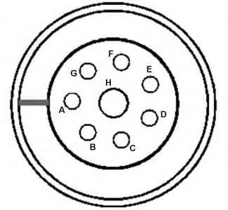
Illustration 1 g06071963 Connector contact
Table 2 Pin Contact Description
Connector/Pin
switched power return (AWAKE RTN)
switched power return (AWAKE RTN)
or
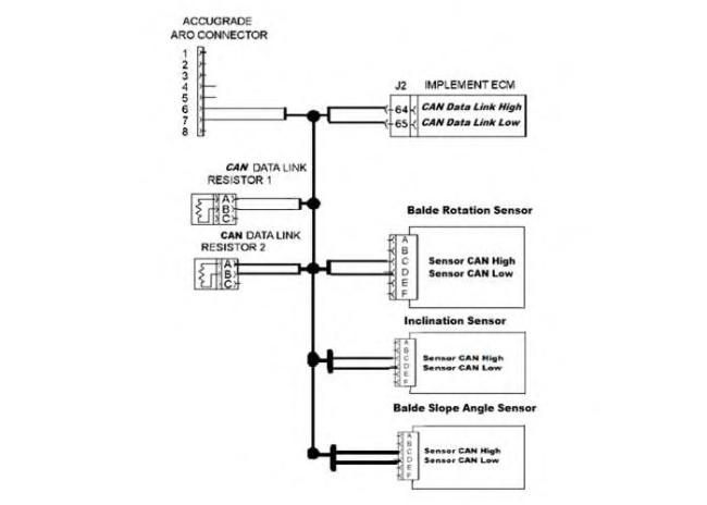
Illustration 2
CAN Data Link
Table 3
Implement ECM 1 (MID 82)
DTC Failure Mode (FMI)
871 13
908 13
3634 13
g06089533
Description
Inclination Sensor / Out of Calibration
Blade Rotation Position Sensor / Out of Calibration
Blade Slope Sensor / Out of Calibration
Code 871 is related to the Inclination (Main-fall) Sensor.
Code 908 is related to the Blade Rotation Sensor.
Code 3694 is related to the Blade Slope Sensor.
When any of the Sensors become loose from the mounting bracket, reinstalled or replaced the Cat Grade control System requires that sensor to be realigned and recalibrated in order for the system to be accurate. Refer to Testing and Adjusting Manual for instructions on aligning and calibrating the Cat Grade Control Sensors.
• The sensor is not secured to the bracket
• The sensor has been removed, reinstalled, or replaced
• Sensors that related to the diagnostic code requires calibration
• Sensor failure
1. Ensure that the sensor related to the diagnostic code is secured to the mounting bracket.
2. Measure the power supply to the sensor connector between Pin A Positive and Pin B RTN GND, ensure that there is close to 24 volt present. Correct any problem.
3. Ensure that the sensor is aligned properly and recalibrate it. Refer to the realigning and calibration section on this manual.
4. Replace the sensor that related to the diagnostic code, align it and then calibrate it.
Table 4
Implement ECM 1 (MID 82)
Blade Slope Sensor Power Supply / voltage above normal 04 Blade Slope Sensor Power Supply / voltage below normal
Blade Rotation Angle Sensor Power Supply / voltage above normal 04
Blade Rotation Angle Sensor Power Supply / voltage below normal
Inclination (Main fall) Sensor Power Supply / voltage above normal 04
Inclination (Main fall) Sensor Power Supply / voltage below normal
Code 3695 with FMI 03 or 04 is related to the Blade Slope Sensor power supply circuit.
Code 3696 with FMI 03 or 04 is related to the Blade Rotation Sensor power supply circuit.
Code 3699 with FMI 03 or 04 is related to the Inclination (Main-fall) Sensor power supply circuit.
Note: The System will generate a Level 2 warning when any of the diagnostic codes in the above table with FMI 03 and FMI 04 become active.
• Intermittent or damages to harness wires connection to the sensor from the Power Module PM400.
• The out power supply from the power module PM400 to the sensor is missing.
• The power module PM400 input power supply is missing.
Note: When the power model power supply is missing, all the system sensors will generate the same failure mode indicating that there is no power supply to them.
• An open circuit
• A component failure of the sensor or the power module PM400.
• Machine implement ECM failure.
Note: Failure of machine ECM is highly unlikely.
1. Visually check the wires and the connectors from the sensors to the implement ECM, ensure that there is no damages or broken wires. Correct any problems.
2. Disconnect the sensor from the machine harness connector and while the machine key switch is in the ON position measure the power supply between Pin A + and Pin B ground ensure that there is a proper power supply (close to 24 volts) from the power model PM400. Correct any problems.
Refer to the Table 5 and 6 or the machine schematic.
3. If there is a power supply present while the sensor is disconnected from the machine harness, measure the power supply to the sensor while it is connected to machine by inserting needle group described in service tool section from the back of the sensor connector to measure the power supply between Pin A + and Pin B ground, ensure that there is sufficient power supply present (close to 24 volts) from the power module PM400 and there is no disappearance or significant drop of the voltage to ensure that there is no internal shortages inside the sensor circuit. Replace the sensor if significant drops of the voltage happened while it is connected to the machine harness.
4. If the power supply is missing to the sensor while the connector is disconnected, ensure that there is a power supply present to the input and the output of the power module PM400 and also the awake and awake RTN is present. Refer to the Table 5 and 6 or the machine schematic for more information.
5. Replace the sensor or the power model PM400 if failure occurs.
6. Replace the Implement ECM.
Note: Failure of machine ECM is highly unlikely.
Illustration 3
Connector contact
Table 5
Pin Description
A + BATT 1
B GND
C + BATT 2
D GND
E -
F -
G + BATT 3
H GND
g06071963
Illustration 4
Connector contact
Table 6
Pin Description
A Switched power 1
B Switched power RTN 1
C Switch power 2
D Switched power RTN 2
E Awake
g06071963
G Switched power 3
H Switched power RTN 3
Troubleshooting the Cat Grade Control System Operator Control (Automatic/Manual) Switches
Table 7 Implement ECM 1 (MID 82)
Left Blade Control Mode (Automatic/Manual) Switch / voltage above normal
Left Blade Control Mode (Automatic/Manual) Switch / voltage below normal
Right Blade Control Mode (Automatic/Manual) Switch / voltage above normal
Right Blade Control Mode (Automatic/Manual) Switch / voltage below normal
Code 2258 with FMI 03 and 04 is related to the Left Blade Control Mode (Automatic/Manuel) Switches circuit.
Code 2259 with FMI 03 and 04 is related to the Right Blade Control Mode (Automatic/Manuel) Switches circuit.
Note: The System will generate a Level 2 warning when any of the diagnostic codes in the above table with FMI 03 and FMI 04 become active.
Probable Causes
• Intermittent or damages to the switch wiring circuit.
• A component has failed (Switch).
• A component has failed (Machine Implement ECM).
Note: Failure of the ECM is highly unlikely.
Steps to Isolate the Problem and Solution
1. Visually check the wires and the connectors from the switch connector to the implement ECM, ensure that there is no damages or broken wires. Correct any problems.
2. Perform contact connections check using an Ohm meter to the switch pins while it is disconnected from the machine harness and replace it, if it is not working properly. Refer to the Table 9.
3. Perform a resistance (Ohm) check of the circuit wires to the machine Implements ECM Connector. Refer to the Table8 or the machine schematic for more information.
4. Replace the Implement ECM if all conditions and steps above are correct and functioning in a proper way.
Note: Failure of machine Implement ECM is highly unlikely.
5. To troubleshoot the automatic/manual switches on the machine equipped with Advance Joystick, refer to machine schematic.
Right and Left Blade Control Mode Switch (Auto/Man Switch)
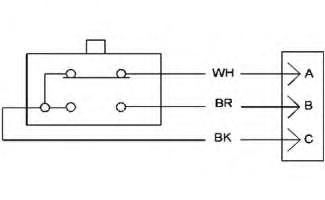
Illustration 5
Wiring Table
g06076493
Table 8
LH/ RH Switch ECM Input Signal LH/ RH Switch Implement ECM Input Signal Pin Circuit Color
A N/C White
B N/O Brown
C Common Black
J2/53 (N/C)
J2/52 (N/O)
J2/22 Digital Return
J2/60 (N/C)
J2/59 (N/O)
J2/22 Digital Return (GND)
Ohm checking the RH/LH Side Blade Control Mode Switches (Auto/Man switches) using ohm meter.
Disconnect the Auto/Man Switch from the machine harness and perform the following contact connection check using the ohm meter
Table 9
RH/LH Auto/Manual Switch
Contact Connections Between When Switch Not Pressed When Switch Pressed
PIN B and PIN A
PIN B and PIN C
PIN A and PIN B
Closed Circuit Opened Circuit
Opened Circuit Closed Circuit
Opened Circuit
Opened Circuit
Table 10
Implement ECM 1 (MID 82)
DTC Failure Mode (FMI)
Diagnostic Code Procedure 2261
03
Left Desired Grade Offset (Increment/Decrement) Switch / voltage above Normal 04
Left Desired Grade Offset (Increment/Decrement) Switch / voltage below Normal
03
Right Desired Grade Offset (Increment/Decrement) Switch / voltage above Normal 04
Right Desired Grade Offset (Increment/Decrement) Switch / voltage below Normal
Code 2261 with FMI 03 or 04 is related to the Left Desired Grade Offset (Increment/decrement) Switch power circuit.
Code 2262 with FMI 03 and 04 is related to the Right Desired Grade Offset (Increment/Decrement) Switch power circuit.
Note: The System will generate a Level 2 warning when any of the diagnostic codes in the above table with FMI 03 and FMI 04 become active.
• Intermittent or damages to the switch wiring circuit.
• A component has failed (Switch).
• A component has failed (Machine Implement ECM).
Note: Failure of ECM is highly unlikely.
1. Visually check the machine harness from the switch connector to the implement ECM connector, ensure that there is no damages or broken wires. Correct any problem.
2. Perform contact connections check using an Ohm Meter to the switch pins while it is disconnected from the machine harness and replace it, if it is not working properly. Refer to the Table 13 or the machine schematic for more information.
3. Disconnect the sensor connector and the machine Implement ECM connector and perform a resistance (Ohm) check of the wires circuit from the Switch Connector to the machine Implements ECM Connector, correct any problem. Refer to the Table 12 and 13 or the machine schematic for more information.
4. Replace the Implement ECM.
Note: Failure of the machine Implement ECM is unlikely.
5. For troubleshooting the RH/LH Increment/Decrement Switches on machine equipped with advanced Joystick, refer to machine schematic.
Table 11
DTC Failure Mode (FMI) Description
2261 02
2262 02
Left Desired Grade Offset (Increment/Decrement) Switch / Data Erratic Intermittent or incorrect
Right Desired Grade Offset (Increment/Decrement) Switch / Data Erratic Intermittent or incorrect
Code 2261 with FMI 02 is related to the Left Desired Grade Offset (Increment/Decrement) Switch data.
Code 2262 with FMI 02 is related to the Right Desired Grade Offset (Increment/Decrement) Switch data.
Note: The System will generate a Level 2 warning when any of the diagnostic codes in the above table with FMI 02 become active.
• The switch digital Input signal to the Implement ECM is intermittent or missing.
1. Visually perform a check to the machine harness from the switch connector wires to the implement ECM connector ensure that there is no damages or broken wires, correct any problem that found.
2. Perform contact connection test of the switch while it is disconnected form the switch. Refer to the Table 13 or the machine schematic.
3. Perform a resistance check from the switch connector to the Implement ECM connector.
4. Disconnect the sensor connector and the machine Implement ECM connector and perform a resistance (Ohm) check of the wires circuit from the Switch Connector to the machine Implements ECM Connector, correct any problem. Refer to the Table 12 and 13 or the machine schematic for more information.
5. Replace the Switch if it is not working properly.
6. Replace the Implement ECM.
Note: Failure of Implement ECM is highly unlikely.
This is the sample of the manual
Click on the download link for complete Manual
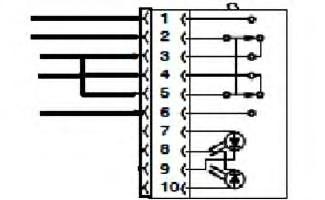
Table 12
To check the switch with an ohm meter, refer to the Table 13 contact connection between the switch pins.
Disconnect the switch connector form the machine harness and perform the following checks using an ohm meter.
Table 13 Contact Connection Between
PIN 2 to PIN 1 Open Connected Open
PIN 2 to PIN 3 Connected Open Connected
PIN 2 to PIN 4 Connected Open Open
PIN 2 to PIN 5 Connected Open Connected
PIN 2 to PIN 6 Open Open Connected
PIN 5 to PIN 1 Open Open Open
PIN 5 to PIN 2 Connected Open Connected
PIN 5 to PIN 3 Connected Connected Connected
PIN 5 to PIN 4 Connected Connected Open
PIN 5 to PIN 6 Open Open Connected
1993 - 2025 Caterpillar Inc.
SIS
Tue May 13 00:48:53 UTC+0530 2025