

Product: SKID STEER LOADER
Model: 248 SKID STEER LOADER 6LZ
Configuration: 236, 246, 248 Skid Steer Loader 6LZ00001-00999 (MACHINE) POWERED BY 3034 Engine
Disassembly and Assembly
236, 246, 248, 252 and 262 Skid Steer Loaders Engine Supplement
Media Number -RENR2868-03 Publication Date -01/08/2004 Date Updated -10/08/2004
Air Cleaner - Remove and Install
SMCS - 1051-010
Removal Procedure
236 and 252 Skid Steer Loaders
1. Lower the work tool to the ground.
2. Turn the engine start switch to the OFF position.
3. Open the engine access door.
4. Release the latch on the radiator. Raise the radiator. This will allow access to the air cleaner.
Note: The 236 and 252 are not equipped with a turbocharger.

Illustration 1 g00766191
5. Disconnect three clamps(3). Remove air cleaner cover (2) from air cleaner housing (1) .
6. Remove the primary air filter and the secondary air filter from inside air cleaner housing (1) .

Illustration 2
g00595258
7. Loosen two clamps (4). Disconnect hose (5) .

Illustration 3
g00595271
8. Remove two bolts (6). Remove air cleaner housing (1) .
9. Remove service indicator (7) .
Removal Procedure
246, 248 and 262 Skid Steer Loaders
1. Lower the work tool to the ground.
2. Turn the engine start switch to the OFF position.
3. Open the engine access door.
4. Release the latch on the radiator. Raise the radiator. This will allow access to the air cleaner.
Note: The 246, 248 and 262are equipped with a turbocharger.
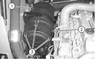
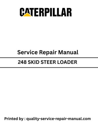
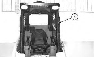
Illustration 4
g00766044
5. Disconnect three clamps(3). Remove air cleaner cover (2) from air cleaner housing (1) .
6. Remove the primary air filter and the secondary air filter from inside air cleaner housing (1) .
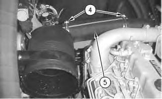
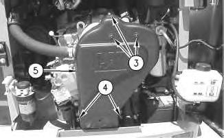
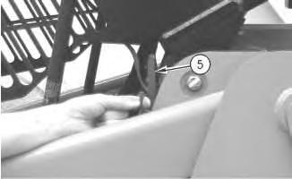
Illustration 5
g00766054
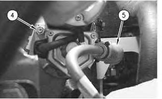
7. Loosen two clamps (4). Disconnect hose (5) .
6
8. Remove two bolts (6). Remove air cleaner housing (1) .
9. Remove service indicator (7) .
Installation Procedure
236 and 252 Skid Steer Loaders
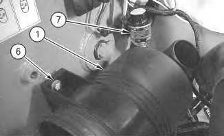
Illustration 7
1. Apply 5P-3413 Pipe Sealant to the threads of service indicator (7). Install service indicator (7) into air cleaner housing (1). Tighten the service indicator until the service indicator makes contact with the base of the fitting. Tighten the service indicator by another 1/4 turn.
2. Clean any debris or dirt from air cleaner housing (1) prior to installation.
3. Place air cleaner housing (1) into position. Install two bolts(6). Tighten two bolts (6) to a torque of 18.5 ± 1.5 N·m (13.6 ± 1.1 lb ft).
Illustration 8
g00595258
4. Connect hose (5). Tighten two clamps (4) to a torque of 4.5 ± 1 N·m (40 ± 9 lb in).
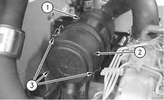
Illustration 9
g00766191
5. Install the primary air filter and the secondary air filter into air cleaner housing (1) .
6. Install air cleaner cover (2) and connect three clamps (3) .
7. Lower the radiator and lock the radiator into position.
8. Close the engine access door.
Installation Procedure
246, 248 and 262 Skid Steer Loaders
10
1. Apply 5P-3413 Pipe Sealant to the threads of service indicator (7). Install service indicator (7) into air cleaner housing (1). Tighten the service indicator until the service indicator makes contact with the base of the fitting. Tighten the service indicator by another 1/4 turn.
2. Clean any debris or dirt from air cleaner housing (1) prior to installation.
3. Place air cleaner housing (1) into position. Install two bolts(6). Tighten two bolts (6) to a torque of 18.5 ± 1.5 N·m (13.6 ± 1.1 lb ft).
11
4. Connect hose (5). Tighten two clamps (4) to a torque of 4.5 ± 1 N·m (40 ± 9 lb in).
5. Install the primary air filter and the secondary air filter into air cleaner housing (1) .
6. Install air cleaner cover (2) and connect three clamps (3) .
7. Lower the radiator and lock the radiator into position.
8. Close the engine access door.
Copyright 1993 - 2020 Caterpillar Inc. All Rights Reserved. Private Network For SIS Licensees.
This is the sample of the manual
Click on the download link for complete Manual
Product: SKID STEER LOADER
Model: 248 SKID STEER LOADER 6LZ
Configuration: 236, 246, 248 Skid Steer Loader 6LZ00001-00999 (MACHINE) POWERED BY 3034 Engine
Disassembly and Assembly
236, 246, 248, 252 and 262 Skid Steer Loaders Engine Supplement Media
i01493213
Alternator - Remove and Install
SMCS - 1405-010
Removal Procedure
1. Lower the work tool to the ground.
2. Turn the engine start switch to the OFF position.
3. Open the engine access door.
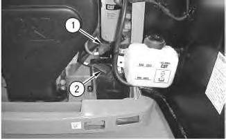
Illustration 1 g00594399
4. Raise the cover on the negative terminal of the battery. Disconnect negative terminal (2) of the battery. Place tape on the negative terminal of the battery.
5. Raise the cover on the positive terminal of the battery. Disconnect positive terminal (1) of the battery. Place tape on the positive terminal of the battery.
2
6. Remove three screws (3) and two bolts (4) .
7. Remove cover (5) .
3
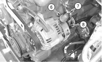
8. Cut tie-wrap (7). Raise rubber boot (6).
9. Disconnect connector (8) .
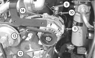
Illustration 4 g00600894
10. Remove nut (10). Disconnect wire (9) .
11. Loosen bolts (12) and (14) .
12. Slide alternator (11) toward the engine.
13. Remove alternator V-belt (13) .
14. Remove bolts (12) and (14) .
15. Remove alternator (11) .
Installation Procedure
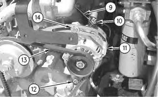
Illustration 5
1. Place alternator (11) in position.
g00600894
2. Install bolts (12) and (14). Do not tighten bolts (12) and (14) at this time.
Note: When you install the alternator, ensure that the alternator pulley is in alignment with the crankshaft pulley within 2.4 mm (0.09 inch).
3. Install alternator V-belt (13) .
4. Slide alternator (11) away from the engine in order to tighten the alternator V-belt (13) .
Note: Refer to the Operation and Maintenance Manual, SEBU7468, "BeltsInspect/adjust/Replace" for the correct procedure.
5. Tighten bolt (14) to a torque of 12 N·m (9 lb ft).
6. Tighten bolt (12) to a torque of 24 N·m (18 lb ft).
7. Connect wire (9). Install nut (10) .

6
8. Connect connector (8) .
9. Install rubber boot (6). Install tie-wrap (7) .
7
10. Place cover (5) in position.
11. Install two bolts (4) to a torque of 15 ± 3 N·m (11 ± 2 lb ft).
12. Install three screws (3) to a torque of 6 ± 1 N·m (53 ± 9 lb in).
13. Remove the tape from the positive terminal of the battery. Connect the positive terminal (1) of the battery. Lower the cover on the positive terminal of the battery.
14. Remove the tape from the negative terminal of the battery. Connect the negative terminal (2) of the battery. Lower the cover on the negative terminal of the battery.
15. Close the engine access door.
Copyright 1993 - 2020 Caterpillar Inc. All Rights Reserved. Private Network For SIS Licensees. Mon Jun 29 10:04:15 UTC+0530 2020
Product: SKID STEER LOADER
Model: 248 SKID STEER LOADER 6LZ
Configuration: 236, 246, 248 Skid Steer Loader 6LZ00001-00999 (MACHINE) POWERED BY 3034 Engine
Disassembly and Assembly
236, 246, 248, 252 and 262 Skid Steer Loaders Engine Supplement
Battery and Battery Cable - Separate and Connect
SMCS - 1401-029
Separation Procedure
1. Lower the work tool to the ground.
2. Turn the engine start switch to the OFF position.
3. Open the engine access door. Illustration 1
i01463322
4. Raise the cover on the negative terminal of the battery. Disconnect negative terminal (2) of the battery. Place tape on the negative terminal of the battery.
5. Raise the cover on the positive terminal of the battery. Disconnect positive terminal (1) of the battery. Place tape on the positive terminal of the battery.

2
6. Remove two bolts (3). Remove bracket (4) on the battery.
7. Remove battery (5) .
Connection Procedure
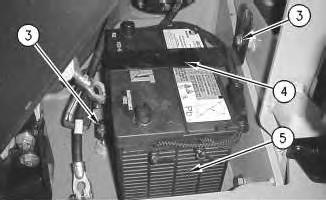
Illustration 3
1. Install battery (5) in position in the machine.
Note: Both battery terminals must be next to the engine.
2. Install bracket (4). Secure bracket (4) with two bolts(3) .
3. Remove the tape from the positive terminal of the battery. Connect the positive terminal (1) of the battery. Lower the cover on the positive terminal of the battery.
4. Remove the tape from the negative terminal of the battery. Connect the negative terminal (2) of the battery. Lower the cover on the negative terminal of the battery.
5. Close the engine access door.
Copyright 1993 - 2020 Caterpillar Inc. All Rights Reserved. Private Network For SIS Licensees. Mon Jun 29 10:03:47 UTC+0530 2020
Product: SKID STEER LOADER
Model: 248 SKID STEER LOADER 6LZ
Configuration: 236, 246, 248 Skid Steer Loader 6LZ00001-00999 (MACHINE) POWERED BY 3034 Engine
Disassembly and Assembly
236, 246, 248, 252 and 262 Skid Steer Loaders Engine Supplement
Cab - Tilt
SMCS - 7301-084
Procedure to Tilt the Cab
Start By:
A. Release the hydraulic system pressure. Refer to Disassembly and Assembly, "Hydraulic System Pressure - Release".
Do not go beneath cab unlesscabisempty and support lever is engaged.
Failure to follow the instructionsor heed the warnings could result in injury or death.
Note: Empty the water tank (if equipped) before you tilt the cab.

Illustration 1
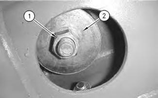
Illustration 2
g00597525
1. Remove nut (1) and large washer (2) from the inside of the cab.
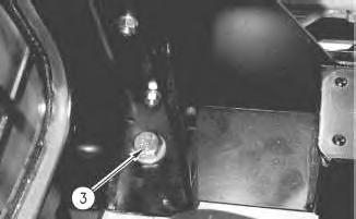
Illustration 3
2. Remove bolt (3) .
g00597551
3. Repeat Steps 1 and 2 on the opposite side of the cab.


6 g00563598
Lower Procedure
7 g00601456


8 g00563674
9
10
Illustration 11
Illustration 12
Note: Ensure that the large washer isbetween the nut and the rubber mounting.
5. Install large washer (2) and nut (1) from the inside of the cab. Tighten the nuts to a torque of 125 ± 10 N·m (92 ± 7 lb ft).
6. Repeat Steps 4 and 5 on the opposite side of the cab. Copyright 1993 - 2020 Caterpillar Inc.
Network For SIS Licensees. Mon Jun 29 10:08:43 UTC+0530 2020
Product: SKID STEER LOADER
Model: 248 SKID STEER LOADER 6LZ
Configuration: 236, 246, 248 Skid Steer Loader 6LZ00001-00999 (MACHINE) POWERED BY 3034 Engine
Disassembly and Assembly
236, 246, 248, 252 and 262 Skid Steer Loaders Engine Supplement Media Number -RENR2868-03
Electric Starting Motor - Remove and Install - 248 Skid Steer Loader
SMCS - 1453-010
S/N- 6LZ1-UP
Removal procedure
Start By:
A. Release the pressure in the hydraulic system. Refer to Disassembly and Assembly, "Hydraulic System Pressure - Release".
Personal injury can result from hydraulic oil pressure and hot oil.
Hydraulic oil pressure can remainin the hydraulic system after the engine has been stopped. Serious injury can be causedif thispressure is not released before any service isdone on the hydraulic system.
Make sure all of the attachments have been lowered, oil is cool before removing any components or lines. Remove the oil filler cap only when the engine isstopped, and the filler capiscool enough to touch with your bare hand. NOTICE
Care must be taken to ensure that fluids are containedduring performance of inspection, maintenance, testing, adjusting and repair of the product. Be prepared to collect the fluid with suitable containers before opening any compartment or disassembling any component containing fluids.
Refer to Special Publication, NENG2500, "Caterpillar Tools and Shop ProductsGuide" for tools and suppliessuitable to collect and contain fluids on Caterpillar products.
Dispose of all fluids according to local regulations and mandates.
1. Lower the work tool to the ground.
2. Turn the engine start switch to the OFF position.
3. Open the engine access door.

4. Raise the cover on the negative terminal of the battery. Disconnect negative terminal (2) of the battery. Place tape on the negative terminal of the battery.
5. Raise the cover on the positive terminal of the battery. Disconnect positive terminal (1) of the battery. Place tape on the positive terminal of the battery.

2
6. Remove hydraulic hose (3) from the pump. Plug the hydraulic hose. Cap the pump fitting.
3
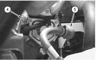
7. Remove nut (4) .
8. Slide boot (5) away from the positive terminal on the electric starting motor.
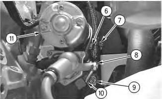
4
9. Remove nut (8). Disconnect the positive cable from the electric starting motor.
10. Remove nut (9). Disconnect the negative cable from the electric starting motor.
11. Disconnect wire (10) .
12. Support electric starting motor (11) .
13. Remove nut (6) and clip (7) .
14. Remove electric starting motor (11) .
Installation Procedure
5
1. Place electric starting motor (11) in position.
2. Install clip (7) and nut (6). Tighten nut (6) to a torque of 50 ± 6 N·m (37 ± 4 lb ft).
3. Install the negative cable to the electric starting motor and install nut (9). Tighten nut (9) to a torque of 50 ± 6 N·m (37 ± 4 lb ft).
4. Connect wire (10) .
5. Connect the positive cable to the electric starting motor and install nut (8) .
This is the sample of the manual
Click on the download link for complete Manual
6
6. Slide boot (5) over the positive terminal of the electric starting motor.
7. Install nut (4). Tighten nut (4) to a torque of 50 ± 6 N·m (37 ± 4 lb ft).
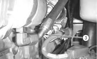
Illustration 7
g00669374
8. Remove the plug from hydraulic hose (3). Remove the cap from pump fitting. Install the hydraulic hose (3) to the hydraulic pump.