Product: SKID STEER LOADER
Model: 246 SKID STEER LOADER 5SZ
Configuration: 236 246 248 Skid Steer Loader 5SZ00001-03999 (MACHINE) POWERED BY 3034 Engine
Disassembly and Assembly
236, 246, 248, 252 and 262 Skid Steer Loaders Engine Supplement
Air Cleaner - Remove and Install
SMCS - 1051-010
Removal Procedure
236 and 252 Skid Steer Loaders
1. Lower the work tool to the ground.
2. Turn the engine start switch to the OFF position.
3. Open the engine access door.
4. Release the latch on the radiator. Raise the radiator. This will allow access to the air cleaner.
Note: The 236 and 252 are not equipped with a turbocharger.
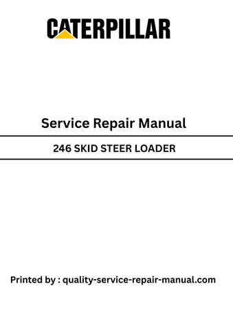
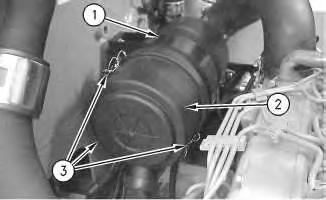
Illustration 1 g00766191
5. Disconnect three clamps(3). Remove air cleaner cover (2) from air cleaner housing (1) .
6. Remove the primary air filter and the secondary air filter from inside air cleaner housing (1) .
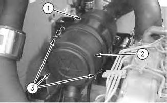
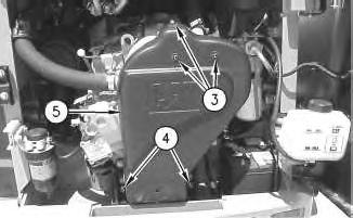
Illustration 2
g00595258
7. Loosen two clamps (4). Disconnect hose (5) .
Illustration 3
g00595271
8. Remove two bolts (6). Remove air cleaner housing (1) .
9. Remove service indicator (7) .
Removal Procedure
1. Lower the work tool to the ground.
2. Turn the engine start switch to the OFF position.
3. Open the engine access door.
4. Release the latch on the radiator. Raise the radiator. This will allow access to the air cleaner.
Note: The 246, 248 and 262are equipped with a turbocharger.
4
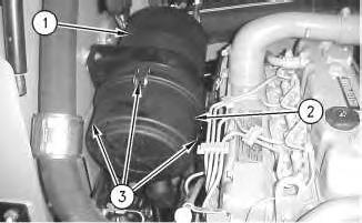
5. Disconnect three clamps(3). Remove air cleaner cover (2) from air cleaner housing (1) .
6. Remove the primary air filter and the secondary air filter from inside air cleaner housing (1) .
5
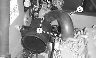
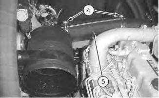
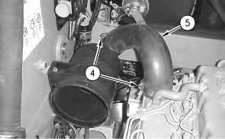
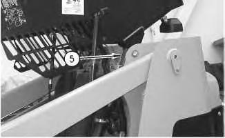
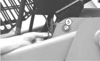
7. Loosen two clamps (4). Disconnect hose (5) .
Illustration
g00766044
Illustration
g00766054
Illustration 6
g00779924
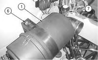
8. Remove two bolts (6). Remove air cleaner housing (1) .
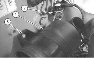
9. Remove service indicator (7) .
Installation Procedure
236 and 252 Skid Steer Loaders
Illustration 7
g00595271
1. Apply 5P-3413 Pipe Sealant to the threads of service indicator (7). Install service indicator (7) into air cleaner housing (1). Tighten the service indicator until the service indicator makes contact with the base of the fitting. Tighten the service indicator by another 1/4 turn.
2. Clean any debris or dirt from air cleaner housing (1) prior to installation.
3. Place air cleaner housing (1) into position. Install two bolts (6). Tighten two bolts (6) to a torque of 18.5 ± 1.5 N·m (13.6 ± 1.1 lb ft).
Illustration 8
g00595258
4. Connect hose (5). Tighten two clamps (4) to a torque of 4.5 ± 1 N·m (40 ± 9 lb in).
Illustration 9
g00766191
5. Install the primary air filter and the secondary air filter into air cleaner housing (1) .
6. Install air cleaner cover (2) and connect three clamps (3) .
7. Lower the radiator and lock the radiator into position.
8. Close the engine access door.
Installation Procedure
246, 248 and 262 Skid Steer Loaders
Illustration 10
g00779924
1. Apply 5P-3413 Pipe Sealant to the threads of service indicator (7). Install service indicator (7) into air cleaner housing (1). Tighten the service indicator until the service indicator makes contact with the base of the fitting. Tighten the service indicator by another 1/4 turn.
2. Clean any debris or dirt from air cleaner housing (1) prior to installation.
3. Place air cleaner housing (1) into position. Install two bolts (6). Tighten two bolts (6) to a torque of 18.5 ± 1.5 N·m (13.6 ± 1.1 lb ft).
Illustration 11
g00766054
4. Connect hose (5). Tighten two clamps (4) to a torque of 4.5 ± 1 N·m (40 ± 9 lb in).
This is the sample of the manual
Click on the download link for complete Manual
Illustration 12
5. Install the primary air filter and the secondary air filter into air cleaner housing (1) .
6. Install air cleaner cover (2) and connect three clamps (3) .
7. Lower the radiator and lock the radiator into position.
8. Close the engine access door.
1993 - 2019 Caterpillar Inc.
Product: SKID STEER LOADER
Model: 246 SKID STEER LOADER 5SZ
Configuration: 236 246 248 Skid Steer Loader 5SZ00001-03999 (MACHINE) POWERED BY 3034 Engine
Disassembly and Assembly
236, 246, 248, 252 and 262 Skid Steer Loaders Engine Supplement
i01493213
Alternator - Remove and Install
SMCS - 1405-010
Removal Procedure
1. Lower the work tool to the ground.
2. Turn the engine start switch to the OFF position.
3. Open the engine access door.
Illustration 1 g00594399
4. Raise the cover on the negative terminal of the battery. Disconnect negative terminal (2) of the battery. Place tape on the negative terminal of the battery.
5. Raise the cover on the positive terminal of the battery. Disconnect positive terminal (1) of the battery. Place tape on the positive terminal of the battery.
Illustration 2
6. Remove three screws (3) and two bolts (4) .
7. Remove cover (5) .
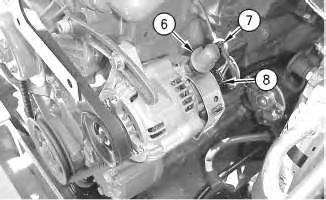
Illustration 3
8. Cut tie-wrap (7). Raise rubber boot (6).
9. Disconnect connector (8) .
g00600705
g00600889
4
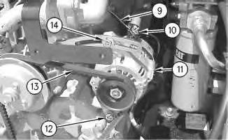
10. Remove nut (10). Disconnect wire (9) .
11. Loosen bolts (12) and (14) .
12. Slide alternator (11) toward the engine.
13. Remove alternator V-belt (13) .
14. Remove bolts (12) and (14) .
15. Remove alternator (11) .
Installation Procedure
Illustration 5
1. Place alternator (11) in position.
2. Install bolts (12) and (14). Do not tighten bolts (12) and (14) at this time.
Illustration
g00600894
g00600894
Note: When you install the alternator, ensure that the alternator pulley is in alignment with the crankshaft pulley within 2.4 mm (0.09 inch).
3. Install alternator V-belt (13) .
4. Slide alternator (11) away from the engine in order to tighten the alternator V-belt (13) .
Note: Refer to the Operation and Maintenance Manual, SEBU7468, "BeltsInspect/adjust/Replace" for the correct procedure.
5. Tighten bolt (14) to a torque of 12 N·m (9 lb ft).
6. Tighten bolt (12) to a torque of 24 N·m (18 lb ft).
7. Connect wire (9). Install nut (10) .
8. Connect connector (8) .
9. Install rubber boot (6). Install tie-wrap (7) .
Illustration 6
g00600889
Illustration 7
10. Place cover (5) in position.
11. Install two bolts (4) to a torque of 15 ± 3 N·m (11 ± 2 lb ft).
12. Install three screws (3) to a torque of 6 ± 1 N·m (53 ± 9 lb in).
Illustration 8
g00594399
13. Remove the tape from the positive terminal of the battery. Connect the positive terminal (1) of the battery. Lower the cover on the positive terminal of the battery.
14. Remove the tape from the negative terminal of the battery. Connect the negative terminal (2) of the battery. Lower the cover on the negative terminal of the battery.
15. Close the engine access door. Copyright 1993 - 2019 Caterpillar Inc. All Rights Reserved. Private Network For SIS Licensees. Fri Sep 27 01:06:29 UTC+0530 2019
Product: SKID STEER LOADER
Model: 246 SKID STEER LOADER 5SZ
Configuration: 236 246 248 Skid Steer Loader 5SZ00001-03999 (MACHINE) POWERED BY 3034 Engine
Disassembly and Assembly
236, 246, 248, 252 and 262 Skid Steer Loaders Engine Supplement
Battery and Battery Cable - Separate and Connect
SMCS - 1401-029
Separation Procedure
1. Lower the work tool to the ground.
2. Turn the engine start switch to the OFF position.
3. Open the engine access door. Illustration 1
i01463322
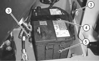
4. Raise the cover on the negative terminal of the battery. Disconnect negative terminal (2) of the battery. Place tape on the negative terminal of the battery.
5. Raise the cover on the positive terminal of the battery. Disconnect positive terminal (1) of the battery. Place tape on the positive terminal of the battery.
Illustration 2
6. Remove two bolts (3). Remove bracket (4) on the battery.
7. Remove battery (5) .
Connection Procedure
Illustration 3
1. Install battery (5) in position in the machine.
Note: Both battery terminals must be next to the engine.
2. Install bracket (4). Secure bracket (4) with two bolts(3) .
g00795046
g00795046
3. Remove the tape from the positive terminal of the battery. Connect the positive terminal (1) of the battery. Lower the cover on the positive terminal of the battery.
4. Remove the tape from the negative terminal of the battery. Connect the negative terminal (2) of the battery. Lower the cover on the negative terminal of the battery.
5. Close the engine access door. Copyright 1993 - 2019 Caterpillar Inc. All Rights Reserved. Private Network For SIS Licensees.
Product: SKID STEER LOADER
Model: 246 SKID STEER LOADER 5SZ
Configuration: 236 246 248 Skid Steer Loader 5SZ00001-03999 (MACHINE) POWERED BY 3034 Engine
Disassembly and Assembly
236, 246, 248, 252 and 262 Skid Steer Loaders Engine Supplement
i01715326
Cab - Tilt
SMCS - 7301-084
Procedure to Tilt the Cab
Start By:
A. Release the hydraulic system pressure. Refer to Disassembly and Assembly, "Hydraulic System Pressure - Release".
Do not go beneath cab unless cab is empty and support lever is engaged.
Failure to followthe instructions or heed the warnings could result in injury or death.
Note: Empty the water tank (if equipped) before you tilt the cab.
Illustration 1
Illustration 2
g00597525
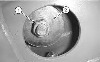
1. Remove nut (1) and large washer (2) from the inside of the cab.
Illustration 3
g00597551
g00601508
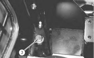
2. Remove bolt (3) .
3. Repeat Steps 1 and 2 on the opposite side of the cab.
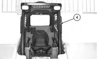
Illustration 4
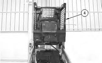
4. Raise cab (4) .
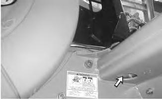
Illustration 5
g00597554
g00601451
Illustration 6 g00563598
.
Lower Procedure
7 g00601456
5. Engage cab support lever (5)
Illustration
Illustration 8 g00563674
Illustration 9 g00601528
1. Tilt the cab upward.
2. Disengage cab support lever (5) .
3. Lower cab (4) .
10
11
12
Illustration
g00597551
4. Install bolt (3) .
Illustration
g00601508
Illustration
g00597525
Note: Ensure that the large washer isbetween the nut and the rubber mounting.
5. Install large washer (2) and nut (1) from the inside of the cab. Tighten the nuts to a torque of 125 ± 10 N·m (92 ± 7 lb ft).
6. Repeat Steps 4 and 5 on the opposite side of the cab. Copyright 1993 - 2019 Caterpillar Inc. All Rights Reserved.
Product: SKID STEER LOADER
Model: 246 SKID STEER LOADER 5SZ
Configuration: 236 246 248 Skid Steer Loader 5SZ00001-03999 (MACHINE) POWERED BY 3034 Engine
Disassembly and Assembly
236, 246, 248, 252 and 262 Skid Steer Loaders Engine Supplement
Electric Starting Motor - Remove and Install
SMCS - 1453-010
S/N- 4YZ1-UP
S/N- 5SZ1-UP
S/N- CED1-UP
S/N- FDG1-UP
Removal procedure
Accidental machine starting can cause injury or death to personnel working on the machine.
To avoid accidental machine starting, turn the battery disconnect switch to the OFF position and remove the key. If the machine isnot equipped with a battery disconnect switch, disconnect the battery cables from the battery and tape the battery clamps.
Place a do not operate tag at the battery disconnect switch location to inform personnel that the machine is being worked on.
1. Lower the work tool to the ground.
i01493237
2. Turn the engine start switch to the OFF position.
3. Open the engine access door.
4. Release the radiator latch. Raise the radiator.
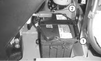
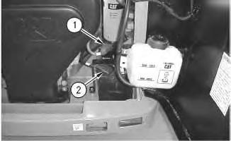
Illustration 1
5. Raise the cover on the negative terminal of the battery. Disconnect negative terminal (1) of the battery. Place tape on the negative terminal of the battery.
6. Raise the cover on the positive terminal of the battery. Disconnect positive terminal (2) of the battery. Place tape on the positive terminal of the battery.
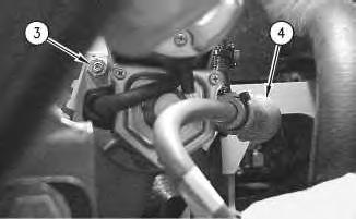
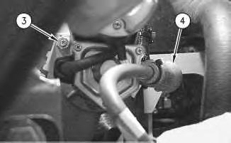
Illustration 2
7. Remove nut (3) .
8. Slide boot (4) away from the positive terminal on the electric starting motor.
g00764870
g00601075
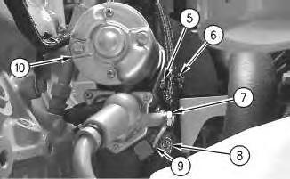
4
9. Remove nut (7). Disconnect the positive cable from the electric starting motor.
10. Remove nut (8). Disconnect the negative cable from the electric starting motor.
11. Disconnect wire (9) .
12. Support electric starting motor (10) .
13. Remove nut (5) and clip (6) .
14. Remove electric starting motor (10) .
Installation Procedure
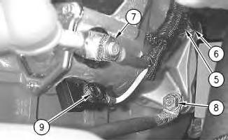
Illustration 3
g00601081
Illustration
g00602154
Accidental machine starting can cause injury or death to personnel working on the machine.
To avoid accidental machine starting, turn the battery disconnect switch to the OFF position and remove the key. If the machine isnot equipped with a battery disconnect switch, disconnect the battery cables from the battery and tape the battery clamps.
Place a do not operate tag at the battery disconnect switch location to inform personnel that the machine is being worked on.
Illustration 5
g00601081
Illustration 6
g00602154
This is the sample of the manual
Click on the download link for complete Manual
1. Place electric starting motor (10) in position.
2. Install clip (6) and nut (5). Tighten nut (5) to a torque of 50 ± 6 N·m (37 ± 4 lb ft).
3. Connect the negative cable to the electric starting motor and install nut (8). Tighten nut (8) to a torque of 50 ± 6 N·m (37 ±4 lb ft).
4. Connect wire (9) .
5. Connect the positive cable to the electric starting motor and install nut (7) .
Illustration 7
g00601075
6. Slide boot (4) over the positive terminal of the electric starting motor.
7. Install nut (3). Tighten nut (3) to a torque of 50 ± 6 N·m (37 ± 4 lb ft).
Illustration 8
g00594399