

Product: SKID STEER LOADER
Model: 228 SKID STEER LOADER 6BZ
Configuration: 216 226 228 Skid Steer Loader 6BZ00001-00699 (MACHINE) POWERED BY 3034 Engine
Disassembly and Assembly
216, 226 and 228 Skid Steer Loaders Engine Supplement
Media Number -RENR2853-02 Publication Date -01/08/2001 Date Updated -16/11/2001
Air Cleaner - Remove and Install
SMCS - 1051-010
Removal Procedure
1. Open the engine access door.
2. Release the latch on the radiator. Raise the radiator. This will allow access to the air cleaner.
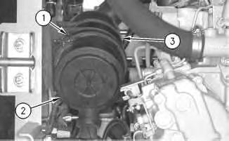
Illustration 1
g00566975
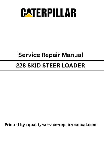
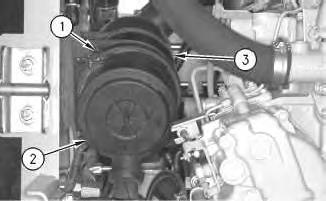
3. Disconnect two clamps(1). Remove air cleaner housing cover (2) from air cleaner housing (3) .
4. Remove the air filter from inside air cleaner housing (3) .
2
5. Remove two hose clamps(4). Remove air hose (5) .
3
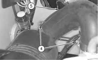
6. Remove two bolts (6) .
7. Remove air cleaner housing (3) .
8. Remove service indicator (7) .
Installation Procedure

4
1. Install service indicator (7) into air cleaner housing (3) .
2. Clean any debris or dirt from air cleaner housing (3) prior to installation.
3. Place air cleaner housing (3) into position. Install two bolts(6) in order to secure air cleaner housing (3) to the side of the machine.
5
4. Install hose (5). Secure hose (5) with two hose clamps(4) .
5. Install the air filter into air cleaner housing (3) .
6. Install air cleaner cover (2) .
7. Connect two clamps(1) .
8. Start the engine and check for air leaks.
9. Turn the engine to the OFFposition. Lower the radiator and lock the radiator into position.
10. Close the engine access door.
1993 - 2020 Caterpillar Inc. All Rights Reserved. Private Network For SIS Licensees. Sun Jan 12 13:33:43 UTC+0530 2020
Product: SKID STEER LOADER
Model: 228 SKID STEER LOADER 6BZ
Configuration: 216 226 228 Skid Steer Loader 6BZ00001-00699 (MACHINE) POWERED BY 3034 Engine
Disassembly and Assembly
216, 226 and 228 Skid Steer Loaders Engine Supplement
Alternator - Remove and Install
SMCS - 1405-010
Removal Procedure
1. Open the engine access door.
i01596954
2. Release the latch on the radiator. Raise the radiator. This will allow access to the alternator.
3. Remove battery cables from the battery. Refer to Disassembly and Assembly, "Battery and Battery Cable - Seperate and Connect".
Illustration 1 g00686047
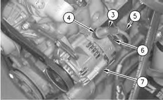
4. Remove five bolts(1).
5. Remove pulley cover (2) from the front of the engine.
2
6. Remove rubber boot (3). Remove nut (4) and remove wire (5) from the alternator.
7. Remove electrical connection (6) from the back of alternator (7) .
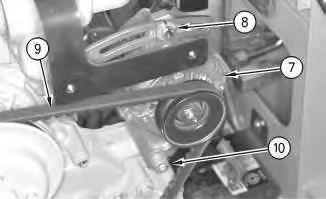
Illustration 3
8. Remove bolt (8). Move alternator (7) in order to release alternator belt (9) .
9. Remove alternator belt (9) from the alternator. Remove bolt (10) and remove alternator (7) .
Installation Procedure
This is the sample of the manual
Click on the download link for complete Manual

4
1. Install alternator (7) and install bolt (10) .
2. Install alternator belt (9) on the alternator pulley.
Note: Refer to the Operation and Maintenance Manual, SEBU7468 for the correct tightening procedure for the alternator belt.
3. Tighten bolt (8) when the proper belt tension is achieved.
5
4. Install electrical connection (6) into the back of alternator (7) .
5. Install electrical wire (5) onto alternator (7). Secure wire (5) with nut (4). Install rubber boot (3) on top of nut (4) .
6. Install pulley cover (2) onto the front of the engine.
7. Secure pulley cover (2) with five bolts (1) .
8. Connect battery cables to the battery. Refer to Disassembly and Assembly, "Battery and Battery Cable - Seperate and Connect".
Note: Check the condition of both the battery cablesand the battery terminal posts. Clean both surfaces for a proper connection.
9. Start the engine.
10. Shut the engine OFF. Check the alternator belt for the proper tension.
11. Lower the radiator.
12. Close the engine access door.
Product: SKID STEER LOADER
Model: 228 SKID STEER LOADER 6BZ
Configuration: 216 226 228 Skid Steer Loader 6BZ00001-00699 (MACHINE) POWERED BY 3034 Engine
Disassembly and Assembly
216, 226 and 228 Skid Steer Loaders Engine Supplement
Battery and Battery Cable - Separate and Connect
SMCS - 1401-029
Separation Procedure
1. Lower the work tool to the ground.
2. Turn the engine start switch to the OFF position.
3. Open the engine access door.
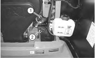
Illustration 1 g00594399
4. Raise the cover on the negative terminal of the battery. Disconnect negative terminal (2) of the battery. Place tape on the negative terminal of the battery.
5. Raise the cover on the positive terminal of the battery. Disconnect positive terminal (1) of the battery. Place tape on the positive terminal of the battery.
2
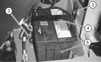
6. Remove two bolts (3). Remove bracket (4) on the battery.
7. Remove battery (5) .
Connection Procedure
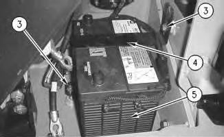
Illustration 3
1. Install battery (5) in position in the machine.
Note: Both battery terminals must be next to the engine.
2. Install bracket (4). Secure bracket (4) with two bolts(3) .
3. Remove the tape from the positive terminal of the battery. Connect the positive terminal (1) of the battery. Lower the cover on the positive terminal of the battery.
4. Remove the tape from the negative terminal of the battery. Connect the negative terminal (2) of the battery. Lower the cover on the negative terminal of the battery.
5. Close the engine access door.
Copyright 1993 - 2020 Caterpillar Inc. All Rights Reserved. Private Network For SIS Licensees. Sun Jan 12 13:30:25 UTC+0530 2020
Product: SKID STEER LOADER
Model: 228 SKID STEER LOADER 6BZ
Configuration: 216 226 228 Skid Steer Loader 6BZ00001-00699 (MACHINE) POWERED BY 3034 Engine
Disassembly and Assembly
216, 226 and 228 Skid Steer Loaders Engine Supplement
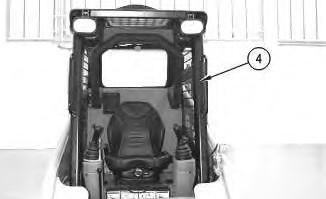
Cab - Tilt
SMCS - 7301-029
Procedure to Tilt the Cab
Start By:
A. Release the hydraulic system pressure. Refer to Disassembly and Assembly, "Hydraulic System Pressure - Release".
Do not go beneath cab unlesscabisempty and support lever is engaged.
Failure to follow the instructionsor heed the warnings could result in injury or death.
Note: Empty the water tank (if equipped) before you tilt the cab.
Illustration 1

Illustration 2
g00597525
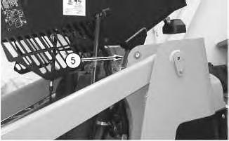
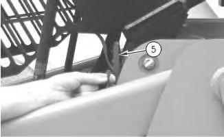
1. Remove nut (1) and large washer (2) from the inside of the cab.
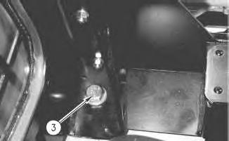
Illustration 3
2. Remove bolt (3) .
g00597551
3. Repeat Steps 1 and 2 on the opposite side of the cab.


6 g00563598
Lower Procedure
7 g00601456


8 g00563674
9
10

Illustration 11
Illustration 12
Note: Ensure that the large washer isbetween the nut and the rubber mounting.
5. Install large washer (2) and nut (1) from the inside of the cab. Tighten the nuts to a torque of 125 ± 10 N·m (92 ± 7 lb ft).
6. Repeat Steps 4 and 5 on the opposite side of the cab. Copyright 1993 - 2020 Caterpillar Inc.
Product: SKID STEER LOADER
Model: 228 SKID STEER LOADER 6BZ
Configuration: 216 226 228 Skid Steer Loader 6BZ00001-00699 (MACHINE) POWERED BY 3034 Engine
Disassembly and Assembly
216, 226 and 228 Skid Steer Loaders Engine Supplement Media Number -RENR2853-02
i01293868
Electric Starting Motor - Remove and Install - 228 Skid Steer Loader
SMCS - 1453-010
S/N- 6BZ1-UP
Removal procedure
1. Release the pressure in the hydraulic system. Refer to Disassembly and Assembly, "Hydraulic System Pressure -Release".
2. Open the engine access door.
3. Release the latch on the radiator. Raise the radiator. This will allow access to the electric starting motor.
4. Remove battery cables from the battery. Refer to Disassembly and Assembly, "Battery and Battery Cable - Seperate and Connect".
Note: Put identification marks on all lines, hoses, wires, and tubes for installation purposes. Plug all lines, hoses, and tubes. This helps prevent fluid lossand contamination of the hydraulic system.

1
5. Remove hydraulic hose from the pump.
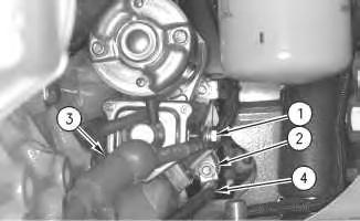
Illustration 2
6. Remove nut (1) and the washer. Remove positive cable (3) of the battery.
7. Remove nut (2) and the washer. Remove negative cable (4) of the battery.
3
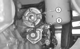
8. Support the electric starting motor (5) in order to prevent the electric starting motor from falling. Remove nut (6) and the washer. Remove the clip from the stud.
9. Remove electric starting motor (5) from the engine.
Installation Procedure

Illustration 4
1. Install electric starting motor (5) onto the flywheel housing.
2. Install the clip. Install the washer and the nut (6) in order to secure the electric starting motor.

Illustration 5
3. Install negative cable (4) of the battery. Secure negative cable (4) and the starter with washer and nut (2) .
4. Install positive cable (3) of the battery. Secure positive cable (3) with washer and nut (2) to the starter.
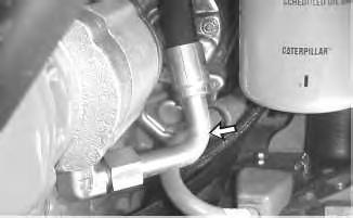
5. Connect hydraulic hose to the pump.
6. Connect battery cables to the battery. Refer to Disassembly and Assembly, "Battery and Battery Cable - Seperate and Connect".
7. Start the engine and check for proper operation of the starter.
8. Lower the radiator.
9. Close the engine access door.
Product: SKID STEER LOADER
Model: 228 SKID STEER LOADER 6BZ
Configuration: 216 226 228 Skid Steer Loader 6BZ00001-00699 (MACHINE) POWERED BY 3034 Engine
Disassembly and Assembly
216, 226 and 228 Skid Steer Loaders Engine Supplement
Media Number -RENR2853-02
Engine - Install
SMCS - 1000-012
Installation Procedure Table 1
RequiredTools
Tool Part Number Part Description Qty
A 1U-9758 Jack Stand 2
B 6U-3145 Load Leveler 1
C 138-7575 Link Bracket 2
D 1U-9759 Jack Stand 1
E 1U-9760 Jack Stand 2
NOTICE
Care must be taken to ensure that fluids are containedduring performance of inspection, maintenance, testing, adjusting and repair of the product. Be prepared to collect the fluid with suitable containers before opening any compartment or disassembling any component containing fluids.
Refer to Special Publication, NENG2500, "Caterpillar Tools and Shop ProductsGuide" for tools and suppliessuitable to collect and contain fluids on Caterpillar products.
Dispose of all fluids according to local regulations and mandates.
NOTICE
Keep all partsclean from contaminants.
Contaminants may cause rapid wear and shortenedcomponent life.
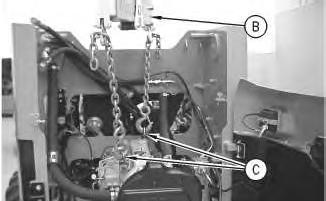
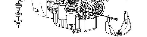
Illustration 1
1. Attach Tooling (B) and Tooling (C ) to the engine.
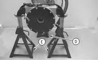
Illustration 2
g00593912
2. Raise the engine from Tooling (E) and Tooling (D). The weight of the engine and pump mount is 293 kg (645 lb).
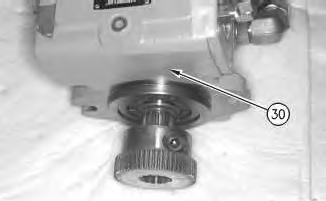
3
3. Install the engine into the engine compartment slowly. Do not snag the wires during installation of the engine. Do not crush the hoses during installation of the engine. Align the coupling hub of the piston pumps(30). Engage the coupling hub of the piston pumps into the pump mounting.
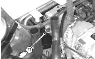
4
4. Install two bolts (27) that secure the piston pumps(30) to the pump mounting.
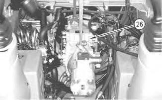
Illustration 5 g00686732
5. Remove the lifting device that wasused to support piston pumps (26) .
6
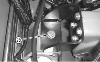
Illustration 7
This is the sample of the manual
Click on the download link for complete Manual
8 g00686735
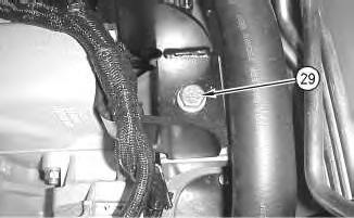
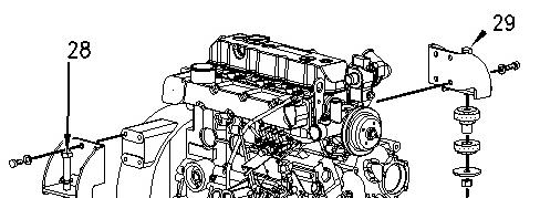
6. Align the rear of the engine with rubber mounts. Install bolts (28) and (29) into the motor mounts that secure the engine to the frame. Torque bolts (28) and (29) to 240 ±40 N·m (177 ± 30 lb ft).
7. Install hoses, tubesand wires that were removed from the engine compartment prior to the installation of the engine.
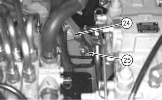
Illustration 9
g00686640
8. Install ground strap (24). Secure ground strap (24) with bolt (25) .