

Previous Screen
Product: MOTOR GRADER
Model: 18M3 MOTOR GRADER E9W
Configuration: 18M Series 3 Motor Grader
Disassembly and Assembly
16M Series 3 and 18M Series 3 Motor Graders Machine
Ripper Lift Cylinder - Remove and Install
SMCS - 5352-010
Cylinders equipped with lock valves can remain pressurized for very long periods of time, even with the hoses removed.
Failure to relieve pressure before removing a lock valve or disassembling a cylinder can result in personal injury or death.
Ensure all pressure is relieved before removing a lock valve or disassembling a cylinder.
NOTICE
Care must be taken to ensure that fluids are contained during performance of inspection, maintenance, testing, adjusting, and repair of the product. Be prepared to collect the fluid with suitable containers
before opening any compartment or disassembling any component containing fluids.
Refer to Special Publication, NENG2500, "Dealer Service Tool Catalog" for tools and supplies suitable to collect and contain fluids on Cat® products.
Dispose of all fluids according to local regulations and mandates.
Hydraulic oil pressure can remain in the hydraulic system on this machine after the engine and pump have been stopped. Serious injury can result if this pressure is not released before any service is done on the hydraulic systems. In order to prevent possible injury, release the hydraulic system pressure before working on any fitting, hose, or hydraulic component.
Lower all attachments to the ground before service is started. If the hydraulic system must be serviced, tested, or adjusted with the attachment in the raised position, the attachments and lift cylinders must be supported properly.
Always move the machine to a location away from the travel of other machines. Be sure that other personnel are not near the machine when the engine is running and tests or adjustments are being made.
NOTICE
Keep all parts clean from contaminants.
Contaminants may cause rapid wear and shortened component life.
1. Release the system pressure. Refer to Operation and Maintenance Manual, "System PressureRelease".
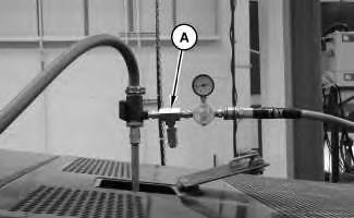
1 g01368952
2. Install Tooling (A) onto the hydraulic tank. Attach an air supply hose onto Tooling (A). Apply 138 kPa (20 psi). This procedure will pull a vacuum on the hydraulic system.
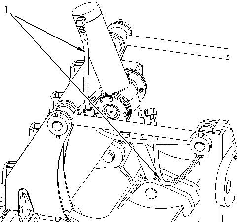
Illustration 2 g00931998
3. Disconnect hose assemblies (1).
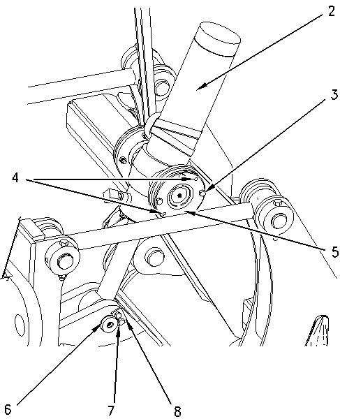
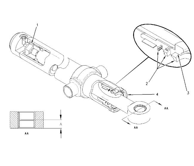
Illustration 3 g00931993
4. Attach a suitable lifting device to ripper lift cylinder (2). The weight of ripper lift cylinder (2) is approximately 91 kg (200 lb).
5. Remove bolts (3). Install Tooling (B) in holes (4). Remove bearing trunnion (5).
6. Repeat Step 5 for the opposite side.
7. Remove bolts (7) and remove plate (8).
8. Remove pin (6).
This is the sample of the manual
Click on the download link for complete Manual
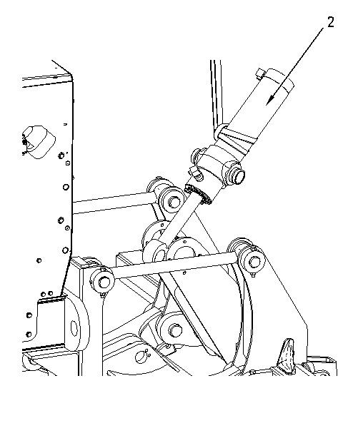
Illustration 4 g00931999
9. Remove ripper lift cylinder (2).
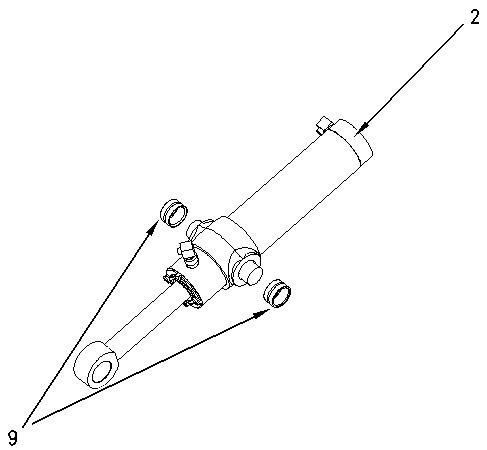
Illustration 5 g00931994
10. Remove bearings (9) from ripper lift cylinder (2).
Disassembly and Assembly Information
Table 2
Required Tools
Tool Part Number Part Description Qty
C 127-4904 Repair Stand 1
D 195-4609 Seal Pick 1
E 7M-7456 Bearing Mount Compound 1
F 1P-0808 Multipurpose Grease 1
G 9U-7868 Spanner Wrench 1 127-8064 Adjustable Plate 1
H 2P-8301 Seal Guide 1
J 1P-1835 Bearing Puller Adapter 1
4C-9634 Puller Stud 1
6V-3170 Double Acting Cylinder 1
Cylinders equipped with lock valves can remain pressurized for very long periods of time, even with the hoses removed.
Failure to relieve pressure before removing a lock valve or disassembling a cylinder can result in personal injury or death.
Ensure all pressure is relieved before removing a lock valve or disassembling a cylinder.
(A) Dimension from the face to the center of the grease groove ... 31.75 ± 0.80 mm (1.250 ± 0.032 inch)
(1) Use a 2 and 9/16 inch socket in order to remove the nut.
(1) Torque for nut ... 3000 ± 300 N·m (2213 ± 221 lb ft)
Note: Lubricate the threads with Tooling (F).
(2) Lubricate sealing lips with a thin covering of the lubricant that is being sealed.
(3) Apply Tooling (E) to the seal groove prior to assembling the wiper seal.
(4) Torque for head ... 600 ± 130 N·m (440 ± 95 lb ft)
Note: Lubricate the threads with Tooling (F).
Installation Procedure
Table 3
Required Tools
Tool Part Number Part Description Qty A 311-1362 Vacuum Cap 1
NOTICE
Keep all parts clean from contaminants.
Contaminants may cause rapid wear and shortened component life.
Illustration 7 g00931994
1. Raise the temperature of bearings (9). Install bearings (9) on ripper lift cylinder (2).
Illustration 8 g00931999
2. Attach a suitable lifting device to ripper lift cylinder (2). The weight of ripper lift cylinder (2) is approximately 91 kg (200 lb). Position cylinder (2) on the machine.
Illustration 9 g00931993
3. Install pin (6).
4. Install plate (8) and install bolts (7).
5. Install bearing trunnion (5). Install bolts (3).
Note: Holes (4) are threaded for Tooling (A).
6. Repeat Step 5 for the opposite side.
7. Remove the suitable lifting device from ripper lift cylinder (2).
This is the sample of the manual
Click on the download link for complete Manual
Illustration 10 g00931998
8. Connect hose assemblies (1).
Illustration 11 g01368952
9. Remove Tooling (A).
10. Check the hydraulic oil level. Refer to Operation and Maintenance Manual, "Hydraulic System Oil Level - Check". Copyright 1993 - 2025 Caterpillar Inc.
Network For SIS Licensees. Tue May 13 00:46:04 UTC+0530 2025