Previous Screen
Product: MOTOR GRADER
Model: 16 MOTOR GRADER 49G
Configuration: NO. 16 MOTOR GRADER 49G00683-UP (MACHINE)
Disassembly and Assembly NO. 16 MOTOR GRADER POWER TRAIN
Media Number -REG01244-00
Publication Date -01/06/1973
Torque Divider Transmission
SMCS - 3110-15; 3110-16
Date Updated -10/10/2001
Disassemble Torque Divider Transmission
start by:
a) separation of torque divider transmission from engine
b) remove selector valve group
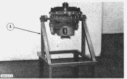
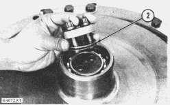
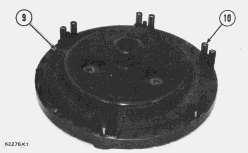
1. Fasten a hoist and put the torque divider transmission in position on stand (A) as shown.
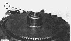
2. Remove the two bolts (1), retainer, and shims (2). Put identification on shims for use during assembly of torque divider transmission.
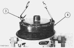
3. Install two 1/2"-13NC forged eyebolts (3).
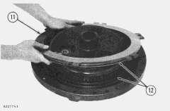
4. Fasten a hoist and remove the No. 1 clutch (4). Weight of clutch is 200 lb. (91 kg).
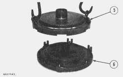
5. Remove the bolts and locks that fasten input flange (5) to No. 1 clutch carrier (6). Remove the input flange from carrier.
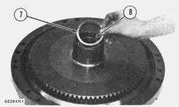
6. Remove retaining ring (7) from input flange, and remove bearing (8).
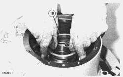
7. Remove the No. 1 clutch springs (10).
8. Remove the disc assembly (9).
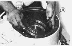
9. Remove the No. 1 clutch piston (11) from the carrier. Remove seal rings (12) from piston and from carrier.
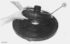
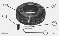
10. Remove the ring gear (13) for No. 1 clutch.
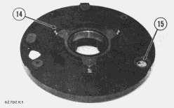
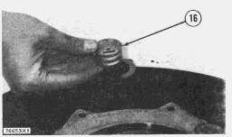
11. Remove the retaining ring (15). Remove dump valve (16) for No. 1 clutch. Remove the spool from dump valve.
12. Remove the bolts (14), locks, and retainers.
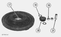
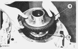
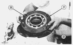
13. Remove the three planet shafts (21), six bearing assemblies (19), six washers (18), and three gears (20) from carrier.
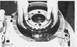
14. Remove retaining ring for sleeve (17). Remove the sleeve (17) and ball from carrier.
15. Remove the retaining ring (24) for sun gear.
16. Remove the sun gear (22) for No. 1 clutch.
17. Remove the spacer (23).
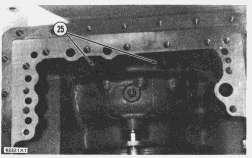
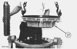
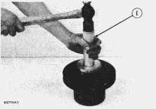
18. Remove the two bolts (25) and the bolts (26) that fasten the torque divider housing to the torque converter housing.
19. Install two 5/8"-11NC forged eyebolts in the torque divider housing.
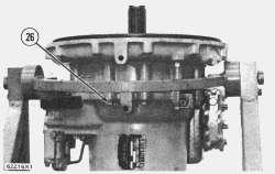
20. Fasten a hoist and remove the No. 2 clutch and torque divider housing (27). Weight of housing and clutch is 190 lb. (86 kg).
21. Remove the ten bolts (28) and washers.
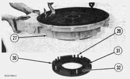
22. Fasten a hoist and remove the torque divider housing (27). Weight of housing is 155 lb. (70 kg).
23. Remove the No. 2 clutch springs (32) and reaction pins (29).
24. Remove the two disc assemblies (30) and plate from No. 2 clutch pressure plate (31).
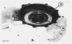
25. Remove No. 2 clutch piston (33) from housing. Remove the seal rings from piston and housing.
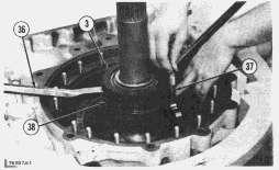
26. Remove the bolts (34) and locks.
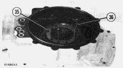
27. Install three 3/8"-16NC forcing screws (36), and remove sleeve (35).
28. Remove the two seal rings from sleeve (35).
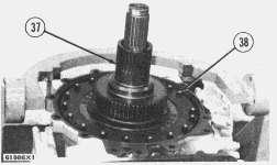
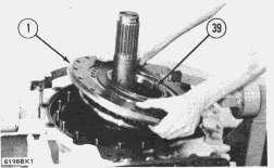
29. Remove the No. 2 clutch gear (37).
30. Remove the retaining ring (39) from gear.
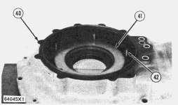
31. Remove the bearing (40) from clutch gear.
This is the sample of the manual
Click on the download link for complete Manual
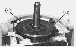
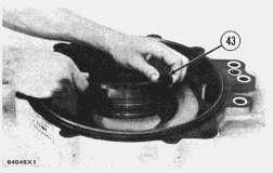
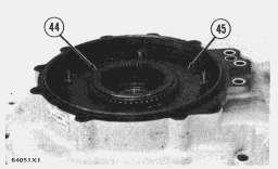
32. Remove the nuts (38). Install three 3/8"-16NC forcing screws (42), and loosen the stator from housing. Remove the stator (41).
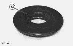
33. Remove the sleeve (43) from stator.
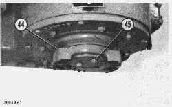
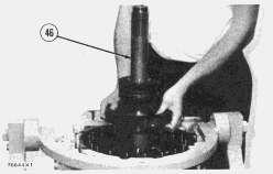
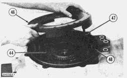
34. Remove the two bolts (45), shims, seal, and output flange (44) from the shaft. Put identification on the shims for use during assembly of transmission.
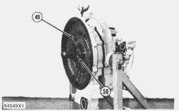
35. Remove the output shaft (46).
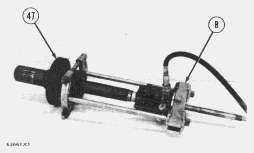
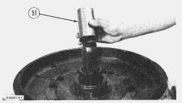
36. Install tooling (B) as shown. Remove the bearing cone, cup, carrier, and impeller (47) from shaft.
37. Remove the seal rings from carrier and from impeller (47).
38. Remove bearing cup and bearing race from the impeller (47).
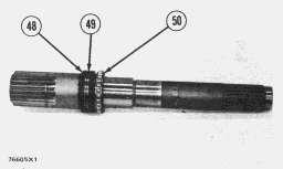
39. Remove bearing assembly (50) and carrier (48) from output shaft. Remove the seal rings (49) from carrier.
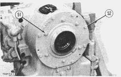
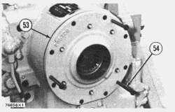
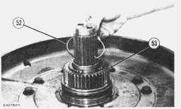
40. Remove the eight bolts (52) and six nuts (51).
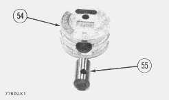
41. Install three 3/8"-16NC forcing screws (54) and loosen retainer (53) from housing. Remove the retainer and shims. Put identification on shims for use during assembly.
42. Remove the lip-type seal from retainer (53).
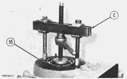
43. Turn the housing into position with output end up as shown. Remove two of the studs (55), and install tooling (C).
44. Remove carrier assembly with tooling (C).
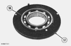
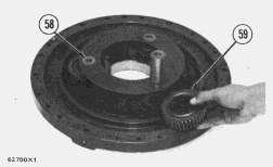
45. Remove the bearing (56) and retaining ring from the carrier.
46. Remove the seal (57) from carrier.
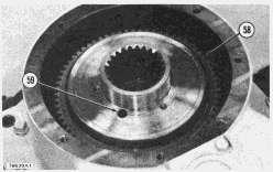
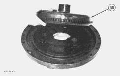
47. Turn the race (58) as needed to remove the four screws that hold the one-way clutch in place. Remove the screws from turbine wheel assembly through access hole (59) in race.
NOTE: The four screws can not be removed completely through race (58).
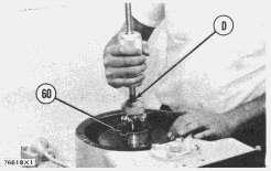
48. Install a 3/8"-24NF x 2 in. bolt (60) and a flat washer. The bolt and washer will hold the oneway clutch together during removal.
NOTICE
The one-way clutch will come apart during removal if the bolt (60) and flat washer are not installed as shown.
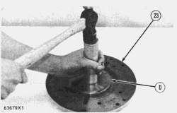
49. Loosen the one-way clutch from the turbine wheel assembly with slide hammer (D).
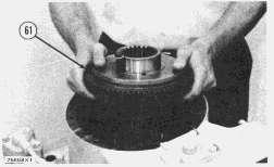
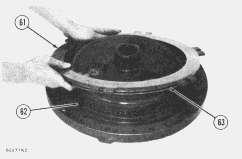
50. Remove the one-way clutch (61).
51. Disassemble the one-way clutch as follows:
a) Remove the bolt (60) and flat washer.
b) Lift up on race (58) just enough to install a rubber band (64) around cam and rollers.
c) Remove the race (58). Remove the roller assembly from cam.
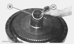
d) Remove the eleven rollers (65), twenty-two followers (67), and twenty-two springs (66).
e) Remove the four screws from cam (63).
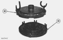
f) Remove cam (63) from cage assembly (62).
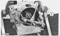
52. Remove the six bolts (68) and retainer (69).
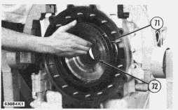
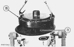
53. Install tooling (E), and remove the carrier (70) and turbine wheel assembly (71).
54. Remove the two seal rings from carrier (70).
55. Remove the sleeve (72) from turbine.
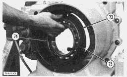
56. Install two 3/8"-16NC forcing screws (75), and remove carrier (73) from housing.
57. Remove the bearing (74) and retaining ring from carrier (73).
Assemble Torque Divider Transmission
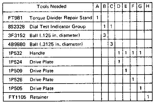
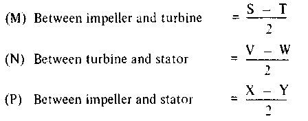
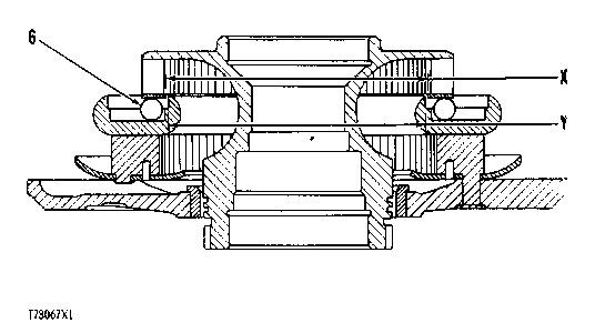
1. The running clearances must be checked before assembling the torque divider transmission. These clearances are:
The running clearances between the respective parts will be equal to one half the total movement reading on dial indicator. Use the following procedure to find these clearances.
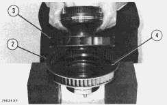
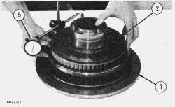
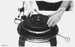
2. Check the running clearance (M) between the impeller (3) and turbine (2) as follows:
a) Put turbine (2) on blocks as shown.
b) Put three balls (4), evenly spaced, from tooling (B) on the turbine.
c) Put impeller (3) in position on turbine. Turn the impeller until the smooth surface of impeller is against the balls.
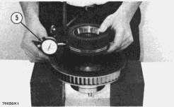
d) Install the indicator group (5) from tooling (B).
e) Move the impeller from side to side (in line with stem of dial indicator). Make a record of the total movement at this location.
f) Check the clearance at three more locations 90° apart. Take the maximum clearance reading and divide it by two to get the running clearance. The running clearance (M) must be .0045 to .0075 in. (0.114 to 0.190 mm).
3. Check the running clearance (N) between the turbine (2) and stator (1) as follows:
a) Put three evenly spaced balls (4) from tooling (B) on the stator.
b) Put the turbine (2) in position on stator (1).
c) Turn the turbine until the smooth surface of turbine is against the balls (4).
d) Install indicator group (5) from tooling (B).
e) Move the turbine from side to side (in line with stem of dial indicator). Make a record of the total movement at this location.
f) Check the clearance at three more locations 90° apart. Take the maximum clearance reading and divide it by two to get the running clearance. The running clearance (N) between turbine and stator must be .006 to .009 in. (0.15 to 0.22 mm).
4. Check the running clearance (P) between the impeller (3) and stator (1) as follows:
a) Put the stator (1) on blocks as shown.
b) Put three evenly spaced balls (6) from tooling (C) on stator.
c) Put the impeller in position on stator.
d) Turn the impeller (3) until the smooth surface of impeller is against the balls.
e) Install indicator group (5) from tooling (C).
f) Move the impeller from side to side (in line with stem of dial indicator). Make a record of the total movement at this location.
g) Check the clearance at three more locations 90° apart. Take the maximum clearance reading and divide it by two to get the running clearance. The running clearance (P) between impeller and stator must be .004 to .0075 in. (0.101 to 0.190 mm).
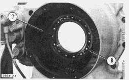
5. Install the bearing (8) and retaining ring in carrier (7).
6. Put the carrier (7) in position in torque converter housing. Install two 3/8"-16NC x 1 in. bolts to temporarily hold the carrier (7) in place.
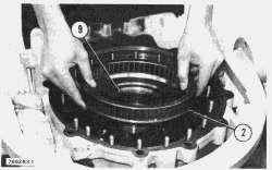
7. Install the sleeve (9) in turbine (2).
8. Turn the housing over on stand (A) with input end up as shown. Put turbine (2) in position in housing. Push the turbine into bearing (8) with a soft hammer.
Make sure the turbine is correctly positioned against bearing (8).
9. Turn the housing over on stand (A) with output end up as shown.
10. Install the two seal rings on carrier (10).
11. Heat the carrier (10) in oil at a maximum temperature of 275°F (135°C). Install the carrier on turbine (2). Make sure the carrier is against bearing (8).
12. Put the seal rings on carrier (10) in the center of their grooves. Remove the two bolts from carrier (7). Softly push retainer (11) into position, and install the six bolts. Tighten the bolts to 36 ± 2 lb.ft. (5.0 ± 0.28 mkg).
13. Put the cam (13) of the one-way clutch in position in cage assembly (12).
14. Install the twenty-two springs (15), twenty-two followers (16), and eleven rollers (14) in cage assembly (12). Use a rubber band to hold the parts in place.
15. Install the roller assembly on the cam and cage assembly.
16. Put the cam and cage assembly of the one-way clutch in position in housing. Make sure the cage assembly is in correct position on the dowels (17) in turbine.
17. Install the four screws that hold the cam to turbine.
18. Put the race (18) in position. Push down on race while turning the race counterclockwise until the rollers (14) are inside of race. Remove the rubber band (19), and push the race completely on to the rollers.
19. Install the bearing (20) and retaining ring in the carrier (21).
20. Install the seal (22) on carrier (21). Put oil on the seal.
21. Put the carrier (21) in place on race (18). Use a soft hammer to push the carrier into position.
22. Install the two studs in carrier (21).
23. Install the seal in retainer (23) with tooling (D). The lip of seal must be toward the inside of retainer. Put oil on lip of seal.
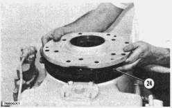
24. Install the original thickness of shims (24) and retainer (23).
NOTE: The shims (24) control the location of the impeller respective to the turbine. Use the original thickness of shims as a beginning point in finding correct location of impeller.
25. Install the eight bolts and six nuts that hold the retainer (23) in place. Tighten the eight bolts to 36 ± 2 lb.ft. (5.0 ± 0.28 mkg).
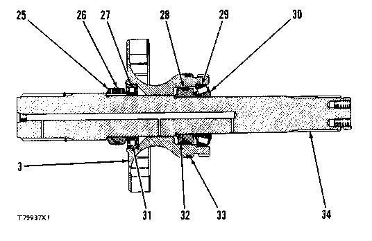
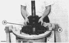
26. Install the four seal rings (26) and (28) on the carriers (25) and (32).
27. Heat the carriers (25) and (32), bearing assembly (31), and bearing cone (30) in oil at a maximum temperature of 275°F (135°C).
28. Install bearing cup (29) and bearing race (27) in impeller (3) with tooling (E). Install the seal rings (33) on impeller.
29. Install the carrier (25) and bearing assembly (31) on output shaft (34).
NOTICE
Make sure carriers (25) and (32) are installed against shoulders of shaft, and bearing assembly (31) and bearing cone (30) are against the carriers.
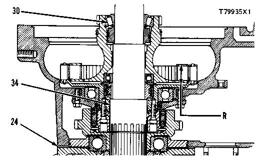
30. Put the impeller (3) in position on shaft, and install carrier (32) and bearing cone (30).
31. Turn the torque converter housing over on stand (A) with input end up as shown.
32. Put oil on the seal rings (26). Put the seal rings in the center of their grooves.
33. Put the output shaft into position in housing. Make sure the ring (35) is in position on shaft.
34. Use two pry bars (36) as shown to lift the impeller (3) until the clearance in bearing (30) has been removed.
NOTICE
Lift impeller (3) only until the clearance in bearing (30) has been removed. Do not lift the shaft (34).
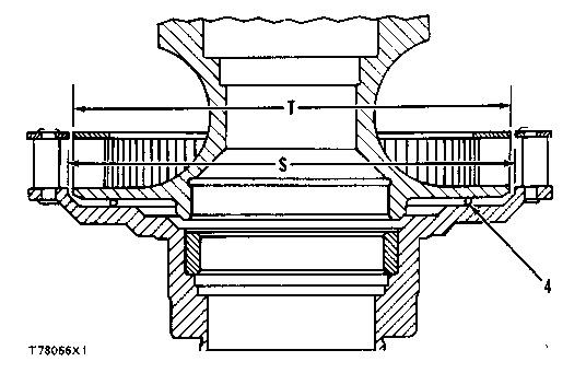
35. While holding up the impeller (3), use a depth micrometer (37) to measure through the two holes in impeller (3) to find dimension (R).
36. The dimension (R) must be 1.416 ± .010 in. (35.966 ± 0.254 mm). Make an adjustment to the thickness of shims (24) to get this dimension. Add shims to decrease the dimension. Remove shims to increase the dimension.
37. Put oil on seal rings (38). Put the seal rings in the center of their grooves.
38. Install the sleeve (39) in stator (1) with tooling (F).
39. Put the stator (1) in position on torque converter housing. Install and tighten the nuts to 36 ± 2 lb.ft. (5.0 ± 0.3 mkg).
40. Put the torque divider housing (40) up on blocks.
41. Install the seal ring in piston (41) and in housing (40). Put oil on the seal rings. Put the seal rings in the center of their grooves.
42. Put the piston (41) in position on housing, and softly push the piston into place.
NOTICE
When installing piston into housing, use care to prevent damage or cause breaking of the seal rings. Never use a hammer to install piston. Broken seal rings can be the result.
43. Install the reaction pins (42) in housing.
44. Install the seal rings on sleeve (43). Put oil on the seal rings.
45. Put the seal rings in the center of their grooves, and install sleeve (43) in housing. Install the six bolts and locks.
46. Use tooling (G) to install the bearing in No. 2 clutch gear (44). Install the retaining ring in gear.
47. Put the No. 2 clutch gear (44) in position in the housing.
48. Install the two disc assemblies (45) and plate beginning with a disc assembly.
49. Put the springs (48) for No. 2 clutch in position on the piston.
50. Install two 1/2"-13NC x 5 in. long guide bolts (47) in the pressure plate (46).
51. Put the pressure plate (46) for No. 2 clutch in position in housing. Make sure the springs (48) are in correct position in plate (46) and in piston.
52. Install two of the bolts that hold plate (46) in position.
53. Install a hose clamp (50) around the small end of the No. 2 clutch gear (44) to hold the gear in position during installation of housing.
54. Install a 5/8"-11NC forged eyebolt in top of the housing. Fasten a hoist and turn the housing over.
55. Remove the two guide bolts (47), and install the remainder of bolts (49).
56. Fasten the hoist to housing, and put the No. 2 clutch and torque divider housing in position on the torque converter housing.
57. Install the bolts that hold the torque divider housing to torque converter housing.
58. Turn the transmission on stand (A) so the input end is up.
59. Remove hose clamp (50) from clutch gear.
60. Install the spacer (51).
61. Put the sun gear (53) for No. 1 clutch in position, and install retaining ring (52).
62. Install the spool (55) in valve (54) with the word "out" on spool toward the outside of the valve as shown.
63. Put the dump valve (54) in position in carrier with the arrow on valve toward outside of carrier and up as shown. Install the retaining ring.
64. Put the sleeve (57) and ball (56) in position in carrier. Install retaining ring.
65. Put the three planet gears (59), six washers, six bearing assemblies, and three shafts in position in carrier. Install the bolts, locks, and retainers that hold the planet shafts (58) in place.
66. Put ring gear (60) for No. 1 clutch in position on carrier assembly.
67. Install seal ring (62) in carrier and seal ring (63) in piston. Put oil on seal rings.
68. Put the seal rings in the center of their grooves. Put the piston (61) in position on carrier, and softly push the piston into place.
NOTICE
When installing piston into carrier, use care to prevent damage or cause breaking of seal rings. Never use a hammer to install piston. Broken seal rings can be the result.
69. Install the disc assembly (64) and springs (65) for No. 1 clutch.
70. Install the bearing (67) in input flange. Install the retaining ring (66) for bearing.
71. Install two 1/2"-13NC forged eyebolts in input flange.
72. Fasten a hoist and put the input flange (68) in position on carrier (69). Make sure the springs are in correct position in the piston and in the input flange.
73. Install the bolts (70) and locks that hold the input flange to the carrier.
74. Put the seal rings (71) in the center of their grooves. Fasten a hoist and put the No. 1 clutch in position. Use care to prevent damage to the seal rings (71).
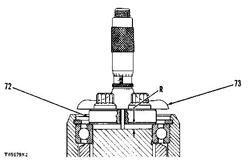
75. To find the correct thickness of shims to use under retainer (75), use the following procedure:
a) Use another retainer (72) with two holes drilled through it on either side of the two bolt holes.
b) Install the special retainer without shims. Install and tighten the two bolts to 80 ± 5 lb.ft. (11.1 ± 0.7 mkg).
c) Use depth micrometer (73) to find dimension (R).
d) Remove the special retainer.
e) Install retainer (75) with shims (76) equal in thickness to dimension (R). Do not install shims of thickness more than .002 in. (0.05 mm) more than dimension (R).
f) Tighten the bolts (74) to 80 ± 5 lb.ft. (11.1 ± 0.7 mkg).
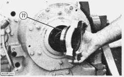
76. Turn the transmission over on stand (A) into position shown.
77. Install output flange (77) on shaft.
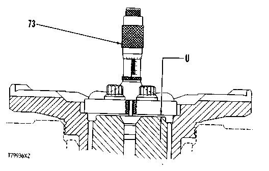
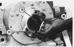
78. To find the correct thickness of shims to use under retainer (80), use the following procedure:
a) Install tool (H) without shims and O-ring seal. Install and tighten bolts (78) to 80 ± 5 lb.ft. (11.1 ± 0.7 mkg).
b) Use depth micrometer (73) to find the dimension (U).
c) Remove tool (H).
d) Install retainer (80), O-ring seal (81), and shims (79) equal in thickness to the dimension (U) minus .001 to .003 in. (0.025 to 0.076 mm).
e) Tighten the bolts (78) to 80 ± 5 lb.ft. (11.1 ± 0.7 mkg).
This is the sample of the manual
Click on the download link for complete Manual
end by:
a) install selector valve group
b) connection of torque divider transmission to engine
Copyright 1993 - 2025 Caterpillar Inc. All Rights Reserved. Private Network For SIS Licensees.
Tue May 13 00:39:08 UTC+0530 2025