163H NA Caterpillar Motor Grader Service Repair Manual
Previous Screen
Product: MOTOR GRADER
Model: 163H NA MOTOR GRADER 5AK
Configuration: 163H Motor Grader 5AK00001-UP (MACHINE) POWERED BY 3306 Engine
Disassembly and Assembly
143H & 163H MOTOR GRADERS POWER TRAIN
Media Number -SENR8553-03
Publication Date -01/11/2004
Brake & Wheel Spindle Housings
SMCS - 4002-011; 4002-012; 4002-015; 4002-016
Remove Brake & Wheel Spindle Housings
Date Updated -31/08/2005
SENR85530004
Start By:
a. remove drive chains
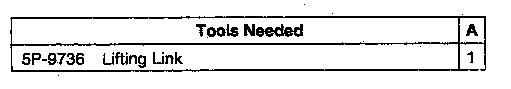
1. Remove two bolts (2), the washers and guard (1) from the brake and wheel spindle housing (3).
Do not disconnect any air line to the machine until the air pressure in the air tank is to zero. Release the air pressure in the air tank by opening the bleed valves. The bleed valves are in the air tank underneath the rear bumper. Close the bleed valves.
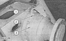
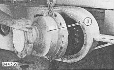
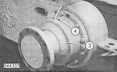
2. Disconnect air line (4) from brake and wheel spindle housing (3). Disconnect the other end of the air line from the block on the tandem housing.
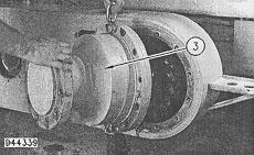
3. Attach Tool (A), a lifting chain and a hoist to brake and wheel spindle housing (3) as shown.
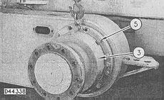
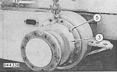
4. Remove bolts (5) and the washers from brake and wheel spindle housing (3).
5. Remove brake and wheel spindle housing (3) from the tandem housing. The weight of brake and wheel spindle housing (3) is 159 kg (350 lb.)
6. Repeat Steps 1 through 5 in order to remove the remaining brake and wheel spindle housing.
Install Brake & Wheel Spindle Housings
1. Attach Tool (A), a lifting chain and a hoist to brake and wheel spindle housing (3) as shown.
2. Position brake and wheel spindle housing (3) on the tandem housing.
3. Install bolts (5) and the washers that hold brake and wheel spindle housing (3) to the tandem housing.
4. Remove the hoist, chain and Tooling (A) from the tandem housing.
5. Install air line (4) on brake and wheel spindle housing (3) and the block on the tandem housing.
6. Position guard (1) on brake and wheel spindle housing (3). Install two bolts (2) and the washers that hold guard (1) to brake and wheel spindle housing (3).
End By:
a. install drive chains
Disassemble Brake & Wheel Spindle Housings
Start By:
a. remove brake and wheel spindle housings
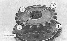
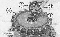
1. Remove wire (3) from bolts (1). Remove bolts (1). Remove retainer (2) and the shims that are under retainer (2).
2. Remove sprocket (4). The weight of sprocket (4) is 16 kg (36 lb).
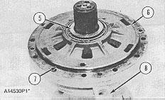
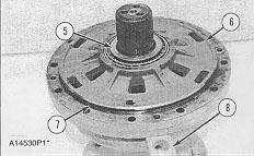
3. Remove bearing cone (5) from the spindle and cover (6). Remove O-ring seal (7) from cover (6).
4. Remove the bolts and plate (8) that hold cover (6) to the housing.
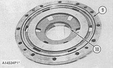
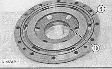
5. Install two 5/8 in - 11 NC Forged Eyebolts in cover (6). Fasten a hoist to the eyebolts and remove cover (6). The weight of cover (6) is 23 kg (50 lb). Remove bearing cup (10) from cover (6).
6. Remove O-ring seal (9) from cover (6).
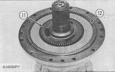
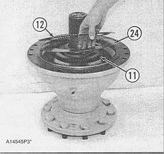
7. Remove hub (11) from the wheel spindle.
8. Remove ten discs (12) and nine discs assemblies from the housing.
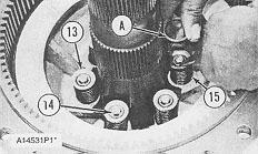
9. Use Tool (A) in order to put springs (15) in compression.
10. Remove rings (14) from the studs with snap ring pliers. Carefully release the compression from springs (15).
11. Remove Tool (A). Remove washers (13) and springs (15) from the studs.
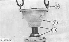
12. Install two 5/8 in - 11 NC Forged Eyebolts (16) in housing (17). Fasten a hoist to the eyebolts.
13. Remove housing (17) from the wheel spindle. The weight of housing (17) is 45 kg (100 lb).
14. Remove Duo-Cone seals (18) from the wheel spindle and housing (17).
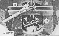
15. Install Tooling (B) and blocks on housing (17) as shown.
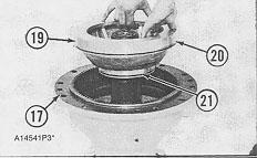
16. Use Tooling (B) in order to remove piston (19) from housing (17).
17. Remove O-ring seals (20) and (21) from piston (19). Remove the bearing cup from housing (17).
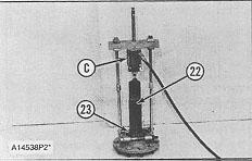
18. Use Tooling (C) in order to remove bearing cone (23) from wheel spindle (22).
19. Perform Steps 1 through 18 for the other brake and wheel spindle housings.
Assemble Brake & Wheel Spindle Housings
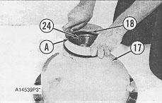
1. Lower the temperature of bearing cup (24) and install it in housing (17).
2. Make sure the Duo-Cone seals for wheel spindle housing (17) and the wheel spindle are clean and dry. Make sure all metal surfaces that the seals make contact with are clean and dry. Use Tool (A) in order to install Duo-Cone seal (18) in wheel spindle housing.
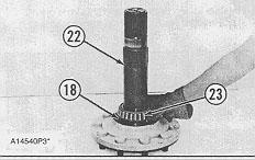
3. Use Tool (A) in order to install Duo-Cone seal (18) on wheel spindle (22). Put a small amount of clean oil on the metal surfaces of the seals that make contract with each other.
4. Heat bearing cone (23), in oil, to a maximum temperature of 135° C (275° F). Install bearing cone (23) on the shaft of wheel spindle (22).
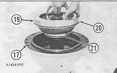
5. Install small O-ring seal (21) on piston (19). Install large O-ring seal (20) on piston (19). Install piston (19) in housing (17).
6. Install two 5/8 in - 11 NC Forged Eyebolts (16) in housing (17). Fasten a hoist to eyebolts (16).
This is the sample of the manual
Click on the download link for complete Manual
7. Put housing (17) in position on wheel spindle (22). Be careful not to damage the Duo-Cone seals. Remove the hoist and eyebolts (16).
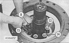
8. Put springs (15) in position on the studs.
9. Put washers (13) in position on the springs.
10. Put springs (15) in compression with Tooling (B).
11. Install rings (14) on the studs with snap ring pliers.
12. Slowly release the pressure on the springs.
13. Remove Tooling (B).
14. Install hub (11) on the wheel spindle.
15. Put clean SAE 30 weight oil on the discs and the disc assemblies.
16. Put discs (12) and disc assemblies (24) in position in wheel spindle housing (17), starting with a disc. There are ten discs and nine disc assemblies. Make sure there is a disc assembly between each disc.
17. Install O-ring seal (9) in cover (6).
18. Lower the temperature of bearing cup (1) and install it in cover (6).
19. Install O-ring seal (7) on cover (6). Put clean oil on the two O-ring seals.
20. Install two 5/8 in - 11 NC Forged Eyebolts in cover (6). Fasten a hoist to the eyebolts.
21. Put cover (6) in position on wheel spindle housing (17). Remove the hoist and the eyebolts.
22. Install the bolts and plate (8) that hold cover (6) to the housing.
23. Install bearing cover (5) on the wheel spindle and in cover (6).
24. Put sprocket (4) in position on the splines of the wheel spindle.
NOTE: The sprocket for the front brake and wheel spindle housing must be installed with the teeth next to the cover. The sprocket for the rear brake and wheel spindle housing must be installed with the teeth away from the cover.
25. Put retainer (2) in position on the wheel spindle without shims (25). Install bolts (1). Tighten the bolts to a torque of 47 N·m (35 lb ft) while rotating the housing relative to the spindle. Without further rotation, remove the bolts and the retainer. Measure the distance between the end of the sprocket and the wheel spindle. Install the retainer and shims (25) that are the same thickness as the distance measured minus 0.25 to 0.38 mm (.010 to .015 in). If additional shims are required, use 9D-7047 Shims. Install bolts (1) that hold retainer (2) on the wheel spindle. Tighten the bolts to a torque of 260 ± 14 N·m (191 ± 10 lb ft). Install the wire on the bolts (1).
End By:
a. install brake and wheel spindle housing
Copyright 1993 - 2025 Caterpillar Inc. All Rights Reserved. Private Network For SIS Licensees. Tue May 13 02:08:51 UTC+0530 2025
Previous Screen
Product: MOTOR GRADER
Model: 163H NA MOTOR GRADER 5AK
Configuration: 163H Motor Grader 5AK00001-UP (MACHINE) POWERED BY 3306 Engine
Disassembly and Assembly
143H & 163H MOTOR GRADERS POWER TRAIN
Media Number -SENR8553-03
Publication Date -01/11/2004
Brake & Wheel Spindle Housings
SMCS - 4002-011; 4002-012; 4002-015; 4002-016
Remove Brake & Wheel Spindle Housings
Date Updated -31/08/2005
SENR85530004
Start By:
a. remove drive chains
1. Remove two bolts (2), the washers and guard (1) from the brake and wheel spindle housing (3).
Do not disconnect any air line to the machine until the air pressure in the air tank is to zero. Release the air pressure in the air tank by opening the bleed valves. The bleed valves are in the air tank underneath the rear bumper. Close the bleed valves.
2. Disconnect air line (4) from brake and wheel spindle housing (3). Disconnect the other end of the air line from the block on the tandem housing.
3. Attach Tool (A), a lifting chain and a hoist to brake and wheel spindle housing (3) as shown.
4. Remove bolts (5) and the washers from brake and wheel spindle housing (3).
5. Remove brake and wheel spindle housing (3) from the tandem housing. The weight of brake and wheel spindle housing (3) is 159 kg (350 lb.)
6. Repeat Steps 1 through 5 in order to remove the remaining brake and wheel spindle housing.
Install Brake & Wheel Spindle Housings
1. Attach Tool (A), a lifting chain and a hoist to brake and wheel spindle housing (3) as shown.
2. Position brake and wheel spindle housing (3) on the tandem housing.
3. Install bolts (5) and the washers that hold brake and wheel spindle housing (3) to the tandem housing.
4. Remove the hoist, chain and Tooling (A) from the tandem housing.
5. Install air line (4) on brake and wheel spindle housing (3) and the block on the tandem housing.
6. Position guard (1) on brake and wheel spindle housing (3). Install two bolts (2) and the washers that hold guard (1) to brake and wheel spindle housing (3).
End By:
a. install drive chains
Disassemble Brake & Wheel Spindle Housings
Start By:
a. remove brake and wheel spindle housings
1. Remove wire (3) from bolts (1). Remove bolts (1). Remove retainer (2) and the shims that are under retainer (2).
2. Remove sprocket (4). The weight of sprocket (4) is 16 kg (36 lb).
3. Remove bearing cone (5) from the spindle and cover (6). Remove O-ring seal (7) from cover (6).
4. Remove the bolts and plate (8) that hold cover (6) to the housing.
5. Install two 5/8 in - 11 NC Forged Eyebolts in cover (6). Fasten a hoist to the eyebolts and remove cover (6). The weight of cover (6) is 23 kg (50 lb). Remove bearing cup (10) from cover (6).
6. Remove O-ring seal (9) from cover (6).
7. Remove hub (11) from the wheel spindle.
8. Remove ten discs (12) and nine discs assemblies from the housing.
9. Use Tool (A) in order to put springs (15) in compression.
10. Remove rings (14) from the studs with snap ring pliers. Carefully release the compression from springs (15).
11. Remove Tool (A). Remove washers (13) and springs (15) from the studs.
12. Install two 5/8 in - 11 NC Forged Eyebolts (16) in housing (17). Fasten a hoist to the eyebolts.
13. Remove housing (17) from the wheel spindle. The weight of housing (17) is 45 kg (100 lb).
14. Remove Duo-Cone seals (18) from the wheel spindle and housing (17).
15. Install Tooling (B) and blocks on housing (17) as shown.
16. Use Tooling (B) in order to remove piston (19) from housing (17).
17. Remove O-ring seals (20) and (21) from piston (19). Remove the bearing cup from housing (17).
18. Use Tooling (C) in order to remove bearing cone (23) from wheel spindle (22).
19. Perform Steps 1 through 18 for the other brake and wheel spindle housings.
Assemble Brake & Wheel Spindle Housings
1. Lower the temperature of bearing cup (24) and install it in housing (17).
2. Make sure the Duo-Cone seals for wheel spindle housing (17) and the wheel spindle are clean and dry. Make sure all metal surfaces that the seals make contact with are clean and dry. Use Tool (A) in order to install Duo-Cone seal (18) in wheel spindle housing.
3. Use Tool (A) in order to install Duo-Cone seal (18) on wheel spindle (22). Put a small amount of clean oil on the metal surfaces of the seals that make contract with each other.
4. Heat bearing cone (23), in oil, to a maximum temperature of 135° C (275° F). Install bearing cone (23) on the shaft of wheel spindle (22).
5. Install small O-ring seal (21) on piston (19). Install large O-ring seal (20) on piston (19). Install piston (19) in housing (17).
6. Install two 5/8 in - 11 NC Forged Eyebolts (16) in housing (17). Fasten a hoist to eyebolts (16).
7. Put housing (17) in position on wheel spindle (22). Be careful not to damage the Duo-Cone seals. Remove the hoist and eyebolts (16).
8. Put springs (15) in position on the studs.
9. Put washers (13) in position on the springs.
10. Put springs (15) in compression with Tooling (B).
11. Install rings (14) on the studs with snap ring pliers.
12. Slowly release the pressure on the springs.
13. Remove Tooling (B).
14. Install hub (11) on the wheel spindle.
15. Put clean SAE 30 weight oil on the discs and the disc assemblies.
16. Put discs (12) and disc assemblies (24) in position in wheel spindle housing (17), starting with a disc. There are ten discs and nine disc assemblies. Make sure there is a disc assembly between each disc.
This is the sample of the manual
Click on the download link for complete Manual
17. Install O-ring seal (9) in cover (6).
18. Lower the temperature of bearing cup (1) and install it in cover (6).
19. Install O-ring seal (7) on cover (6). Put clean oil on the two O-ring seals.
20. Install two 5/8 in - 11 NC Forged Eyebolts in cover (6). Fasten a hoist to the eyebolts.
21. Put cover (6) in position on wheel spindle housing (17). Remove the hoist and the eyebolts.
22. Install the bolts and plate (8) that hold cover (6) to the housing.
23. Install bearing cover (5) on the wheel spindle and in cover (6).
24. Put sprocket (4) in position on the splines of the wheel spindle.
NOTE: The sprocket for the front brake and wheel spindle housing must be installed with the teeth next to the cover. The sprocket for the rear brake and wheel spindle housing must be installed with the teeth away from the cover.
25. Put retainer (2) in position on the wheel spindle without shims (25). Install bolts (1). Tighten the bolts to a torque of 47 N·m (35 lb ft) while rotating the housing relative to the spindle. Without further rotation, remove the bolts and the retainer. Measure the distance between the end of the sprocket and the wheel spindle. Install the retainer and shims (25) that are the same thickness as the distance measured minus 0.25 to 0.38 mm (.010 to .015 in). If additional shims are required, use 9D-7047 Shims. Install bolts (1) that hold retainer (2) on the wheel spindle. Tighten the bolts to a torque of 260 ± 14 N·m (191 ± 10 lb ft). Install the wire on the bolts (1).
End By:
a. install brake and wheel spindle housing
Copyright 1993 - 2025 Caterpillar Inc. All Rights Reserved. Private Network For SIS Licensees. Tue May 13 02:09:00 UTC+0530 2025