

Previous Screen
Product: MOTOR GRADER
Model: 160K MOTOR GRADER SZM
Configuration: 160K Motor Grader SZM00001-UP (MACHINE) POWERED BY C7 Engine
Disassembly and Assembly C7
Engines for Caterpillar Built Machines
Fuel Filter Base - Remove and Install
SMCS - 1262-010
Removal Procedure
Fuel leaked or spilled onto hot surfaces or electrical components can cause a fire. To help prevent possible injury, turn the start switch off when changing fuel filters or water separator elements. Clean up fuel spills immediately.
NOTICE
Care must be taken to ensure that fluids are contained during performance of inspection, maintenance, testing, adjusting and repair of the product. Be prepared to collect the fluid with suitable containers before opening any compartment or disassembling any component containing fluids.
Refer to Special Publication, NENG2500, "Caterpillar Tools and Shop Products Guide" for tools and supplies suitable to collect and contain fluids on Caterpillar products.
Dispose of all fluids according to local regulations and mandates.
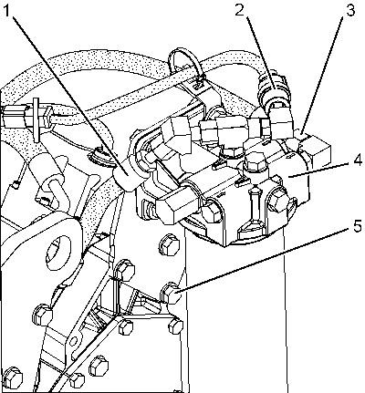
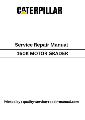
Illustration 1 g01152090
1. Disconnect hose assembly (1) and hose assembly (3) .
2. Disconnect harness assembly (2) .
3. Remove bolts (5) and fuel filter base (4) .
Installation Procedure NOTICE
Keep all parts clean from contaminants.
Contaminants may cause rapid wear and shortened component life.
Illustration 2
1. Position fuel filter base (4) on the engine.
2. Install bolts (5) .
3. Connect harness assembly (2) .
4. Connect hose assembly (3) and hose assembly (1) .
Copyright 1993 - 2025 Caterpillar Inc. All Rights Reserved. Private Network For SIS Licensees.
Tue May 13 01:55:07 UTC+0530 2025
Previous Screen
Product: MOTOR GRADER
Model: 160K MOTOR GRADER SZM
Configuration: 160K Motor Grader SZM00001-UP (MACHINE) POWERED BY C7 Engine
Disassembly and Assembly C7
Engines for Caterpillar Built Machines
Fuel Transfer Pump - Install
SMCS - 1256-012
Installation Procedure Table 1
Keep all parts clean from contaminants.
Contaminants may cause rapid wear and shortened component life.
i06716882
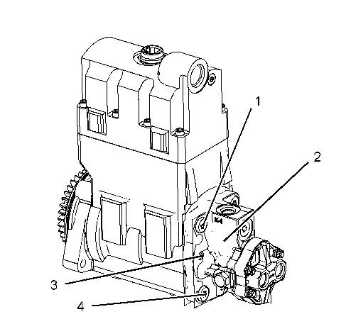
Illustration 1 g01123057
1. Position fuel transfer pump (2) on the unit injector hydraulic pump. Be sure to align the drive tang of the fuel transfer pump to the drive slot in the end of the pump shaft.
2. Install tie bolts (4). Tighten the bolts to a snug fit.
3. Remove Tooling (A) that is located in the upper left hole and install remaining tie bolt (1) to a snug fit.
4. Install bolts (3) for fuel transfer pump (2). Tighten the bolts to a snug fit.
5. Start in the lower left corner of the unit injector hydraulic pump and tighten tie bolts (4) to a torque of 28 ± 2 N·m (21 ± 1 lb ft) in a crisscross pattern. Torque the bolts again.
6. Tighten bolts (3) to a torque of 8.0 ± 0.4 N·m (71 ± 4 lb in).
End By:
a. Install the unit injector hydraulic pump. Refer to Disassembly and Assembly, "Unit Injector Hydraulic Pump - Install".
Previous Screen
Product: MOTOR GRADER
Model: 160K MOTOR GRADER SZM
Configuration: 160K Motor Grader SZM00001-UP (MACHINE) POWERED BY C7 Engine
Disassembly and Assembly C7
Engines for Caterpillar Built Machines Media
Unit Injector Hydraulic Pump - Remove
SMCS - 1714-011
i05683072
Removal Procedure for Non-Dual Tapered Roller Bearing HEUI Pump
Table 1 Required Tools
NOTICE
Keep all parts clean from contaminants.
Contaminants may cause rapid wear and shortened component life.
NOTICE
Care must be taken to ensure that fluids are contained during performance of inspection, maintenance, testing, adjusting, and repair of the product. Be prepared to collect the fluid with suitable containers before opening any compartment or disassembling any component containing fluids.
Refer to Special Publication, NENG2500, "Dealer Service Tool Catalog" for tools and supplies suitable to collect and contain fluids on Cat products.
Dispose of all fluids according to local regulations and mandates.
2
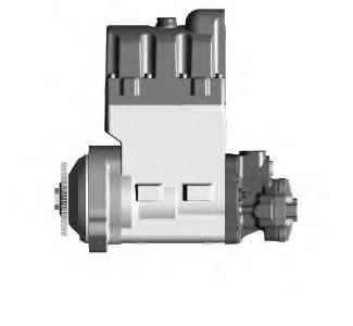
Dual Taper Roller Bearing HEUI pump
Note: Refer to Illustrations 1 and 2 in order to identify each unit injection hydraulic pump.
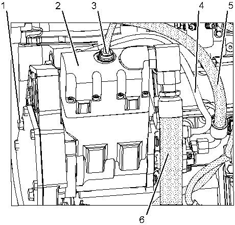
Illustration 3 g01152147
1. Disconnect hose assembly (5) and tube assembly (4) .
2. Use Tooling (A) in order to disconnect hose assembly (6) .
3. Disconnect harness assembly (3) from unit injector hydraulic pump (2) .
4. Remove bolts (1) . Remove unit injector hydraulic pump (2) .
Removal Procedure for Dual Tapered Roller Bearing HEUI Pump Table 2
NOTICE
Keep all parts clean from contaminants.
Contaminants may cause rapid wear and shortened component life.
NOTICE
Care must be taken to ensure that fluids are contained during performance of inspection, maintenance, testing, adjusting, and repair of the product. Be prepared to collect the fluid with suitable containers before opening any compartment or disassembling any component containing fluids.
Refer to Special Publication, NENG2500, "Dealer Service Tool Catalog" for tools and supplies suitable to collect and contain fluids on Cat products.
Dispose of all fluids according to local regulations and mandates.
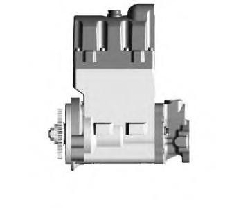
Illustration 5
Dual Taper Roller Bearing HEUI pump
g03601540
Note: Refer to Illustrations 4 and 5 in order to identify each unit injection hydraulic pump.
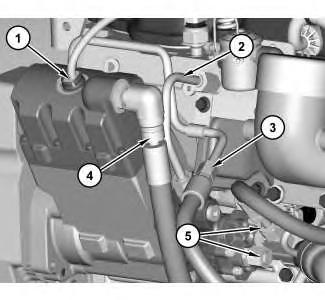
Illustration 6
g03593456
1. Disconnect harness assembly (1) . Use Tooling (A) in order to disconnect hose assembly (4) . Disconnect hose assemblies (3) and (5) and position aside. Remove tube assembly (2) .
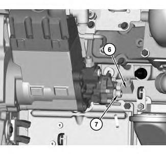
Illustration 7
2. Remove adapters (6) and (7) .
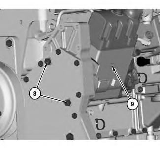
Illustration 8
3. Support unit injector hydraulic pump (8) and remove bolts (9) .
This is the sample of the manual
Click on the download link for complete Manual
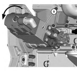
Illustration 9
4. Rotate unit injector hydraulic pump (9) counterclockwise as shown, then remove unit injector hydraulic pump (9) .
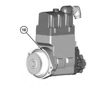
Illustration 10
5. Remove O-ring seal (10) .
g03593461
Tue May 13 01:55:33 UTC+0530 2025