

Product: MOTOR GRADER
Model: 160H NA MOTOR GRADER 9EJ
Configuration: 160H Motor Grader 9EJ00001-UP (MACHINE) POWERED BY 3306 Engine
Disassembly and Assembly
26SI Series Alternator
Media Number -RENR1252-01
Alternator - Assemble
SMCS - 1405-016
Assembly Procedure
-01/10/1999
-09/10/2001
i01167078
Note: Cleanliness is an important factor. Before assembly, all parts should be thoroughly cleaned in cleaning fluid. Allow the parts to air dry. Wiping cloths or rags should not be used to dry parts. Lint may be deposited on the parts which may cause later trouble. Inspect all parts. If any parts are worn or damaged, use new parts for replacement.
Note: Do not strike the diodes. The shock of such an impact can damage the diodes. Use proper tools in order to press the diodes in the mountings.
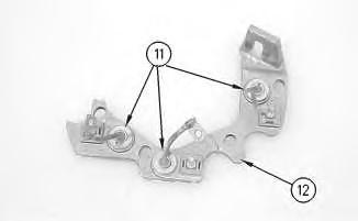
Illustration 1
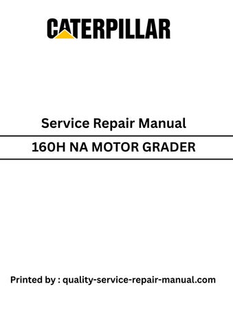
1. Install 3 diodes (11) in heat sink (12) .
g00628072

Illustration 2
g00628068
Note: Do not strike the bushing. Shocks from striking the housing can cause damage.
2. Press bushing (43) in housing (14) .
3. Install 3 diodes (13) in housing (14) .
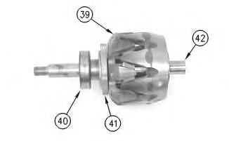
Illustration 3
Illustration 4
g00628063
7. Press housing (31) on rotor (39) and bearing (40) .
8. Install 4 screws (38) in housing (31) .
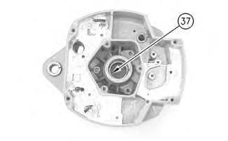
Illustration 5
g00628057
Note: Do not strike the bearing. Shocks from striking the housing can cause damage.
9. Install the inner race. Press bearing (37) into the housing.
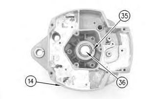
Illustration 6
10. Press cap (36) in housing (14) .
g00628043
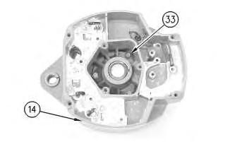
Illustration 7
g00628041
11. Install the coil and support (34) in housing (14). Guide the field leads and the grommet through the hole as the coil is installed in housing (14). Install 3 screws (33) .
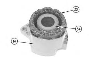
Illustration 8
g00628037
12. Press the stator (32) and housing (14) together. Guide the stator leads and the grommet through the hole as the stator is installed in housing (14) .
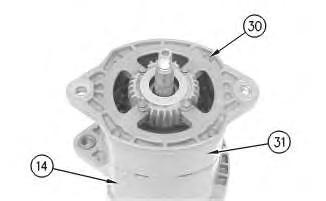
Illustration 9
g00628035
Note: Do not damage exposed stator windings or field windings. Bumping the windings or scraping the windings may break the insulation. Broken insulation may create a short circuit or a ground.
13. Join housing (31) and housing (14). Install 4 bolts (30) .

Illustration 10
g00627853
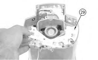
Note: Many of the alternator's internal components are covered with dielectric grease. If the grease is removed, reapply the grease.
11
14. Install Insulator (29). Install the heat sink and diode assembly (12) in housing (14) .
12
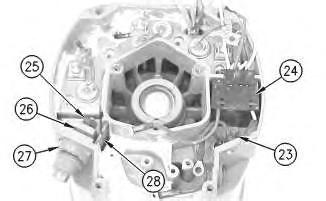
15. Install separator (28) .
16. Install alternator output terminal (27). Install insulator (26). Install the nut and washer (25) .
17. Install diode trio (24) and install screw (23) .
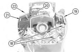
Illustration 13
g00627832
18. Install the 3 screws and insulators (18). Connect wire (19) .
19. If the "R" terminal is used, install the following components: nut (20), lead (21), the washer and terminal (21) .

Illustration 14
g00627820
20. Install the screw and insulator (16). Connect capacitor lead (17) .
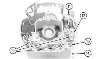
Illustration 15
g00627810
Note: The 3 output diodes (11) are located in heat sink (12). These diodes are identical in polarity. Diode (11) has red insulation on the wire. The 3 ground diodes (13) are located in housing (14). These diodes are identical in polarity. Diode (13) has black insulation on the wire.
21. Connect 6 diode leads. Connect 3 phase leads. Connect 3 stator phase leads. Install 3 nuts (15).
Table 1
This is the sample of the manual
Click on the download link for complete Manual
Alternator Ground
Negative
Current Flow of the Output Diodes
Lead to the Heat Sink
Current Flow of the Ground Diodes
Housing to the Lead Red Wire Black Wire

Illustration 16
22. Install mounting plate (10).
g00627808

Illustration 17
23. Install regulator (9) .
24. Install grounded mounting screw (8) .
g00627804
18
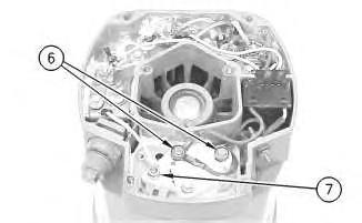
25. Install 2 insulated screws (6). Connect the 3 leads.
Note: The regulator and the mounting plate are coated with dielectric grease. If the grease is removed, reapply the grease.
26. Install nut (7) and connect the wire.
19
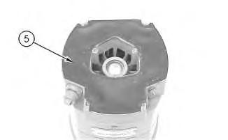
27. Install gasket (5) .
20
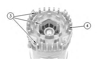
28. Position cover (4). Install 7 screws (3) .
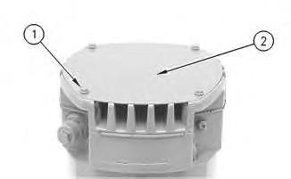
21
29. Position plate (2). Install 4 screws (1) .
30. Install the fan, the pulley, the washer, and the pulley nut.
1993 - 2021 Caterpillar Inc. All Rights Reserved.
Network For SIS Licensees. Thu Nov 25 22:56:52 UTC+0530 2021
Product: MOTOR GRADER
Model: 160H NA MOTOR GRADER 9EJ
Configuration: 160H Motor Grader 9EJ00001-UP (MACHINE) POWERED BY 3306 Engine
Disassembly and Assembly
26SI Series Alternator
Media Number -RENR1252-01
Alternator - Disassemble
SMCS - 1405-015
Disassembly Procedure
Table 1 Required Tools
Start By:
A. Remove the alternator. Refer to Disassembly and Assembly, "Alternator - Remove" for the machine that is being serviced.
Note: Cleanliness is an important factor. Before the disassembly procedure, the exterior of the component should be thoroughly cleaned. This will help to prevent dirt from entering the internal mechanism.
1. Remove the pulley nut, the washer, the pulley, and the fan.
Illustration 1
2. Remove 4 screws (1). Remove plate (2) .
Illustration 2
3. Remove 7 screws (3). Remove cover (4) .
Illustration 3
4. Remove gasket (5) .
Illustration 4
5. Remove 2 insulated screws (6). Remove the 3 leads.
Note: The regulator and the mounting plate are coated with dielectric grease. If the grease is removed, reapply the grease.
6. Remove nut (7) .
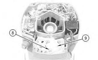
Illustration 5
7. Remove grounded mounting screw (8) .
8. Remove regulator (9) .
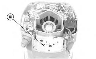
Illustration 6
g00627808
9. Remove mounting plate (10). The mounting plate may be stuck to the regulator.
Illustration 7
g00627810
Note: The 3 output diodes (11) are located in heat sink (12). These diodes are identical in polarity. Diode (11) has red insulation on the wire. The 3 ground diodes (13) are located in housing (14). These diodes are identical in polarity. Diode (13) has black insulation on the wire.
10. Remove 3 nuts (15). Disconnect 3 stator phase leads. Disconnect 3 phase leads. Disconnect 6 diode leads.
Table 2
Alternator Ground Current Flow of the Output Diodes Current Flow of the Ground Diodes
Negative
Lead to the Heat Sink Housing to the Lead Red Wire Black Wire
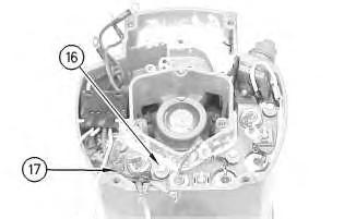
Illustration 8
g00627820
11. Remove the screw and insulator (16). Disconnect capacitor lead (17) .
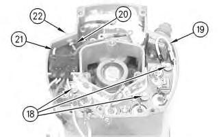
Illustration 9
g00627832
12. Remove the 3 screws and insulators (18). Disconnect wire (19) .
13. If the "R" terminal is used, remove the following components: nut (20), lead (21), the washer and terminal (21) .
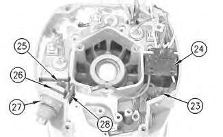
Illustration 10
14. Remove screw (23) and remove diode trio (24) .
15. Remove the nut and washer (25). Remove insulator (26). Remove alternator output terminal (27) .
16. Remove separator (28) .
Illustration 11
g00627853
Note: Many of the alternator's internal components are covered with dielectric grease. If the grease is removed, reapply the grease.

Illustration 12
g00627855
17. Remove the heat sink and diode assembly (12) from housing (14). Insulator (29) may be stuck to heat sink (12) .
Illustration 13
g00628035
Note: Do not damage exposed stator windings or field windings. Bumping the windings or scraping the windings may break the insulation. Broken insulation may create a short circuit or a ground.
18. Remove 4 bolts (30). Carefully separate housing (31) from housing (14) .

Illustration 14
g00628037
19. Pull apart stator (32) and housing (14). Guide the stator leads and the grommet through the hole as the stator is removed from housing (14) .
Illustration 15
g00628041
20. Remove 3 screws (33). Remove the coil and support (34) from housing (14). Guide the field leads and the grommet through the hole as the coil is removed from housing (14) .
Illustration 16
g00628043
21. Position a small screwdriver in slot (35). Pry cap (36) from housing (14) .
Illustration 17
g00628057
Note: Do not strike the bearing. Shocks from striking the housing can cause damage.
22. Wipe the excess grease from the bearing well. Press bearing (37) into the housing. Remove the inner race.
Illustration 18
23. Remove 4 screws (38) from housing (31) .
g00628063
24. Lift rotor (39) and bearing (40) from housing (31) .
Illustration 19
25. Pull bearing (40) from rotor (39) .
26. Pull retainer (41) from rotor (39) .
27. Pull collar (42) from rotor (39) .
g00628067
Illustration 20
g00628068
Note: Do not strike the bushing. Shocks from striking the housing can cause damage.
28. Press bushing (43) from housing (14) .
Note: Do not strike the diodes. The shock of such an impact can damage the diodes. Use proper tools in order to press or pull the diodes from the mountings. As much as 890 N (200 lb) of force may be needed to remove a diode.
29. Remove 3 diodes (13) from housing (14) .
Illustration 21
30. Remove diode (11) from heat sink (12) .
g00628072
Copyright 1993 - 2021 Caterpillar Inc. All Rights Reserved. Private Network For SIS Licensees. Thu Nov 25 22:56:34 UTC+0530 2021
Product: MOTOR GRADER
Model: 160H NA MOTOR GRADER 9EJ
Configuration: 160H Motor Grader 9EJ00001-UP (MACHINE) POWERED BY 3306 Engine
Disassembly and Assembly
Comfort Series Seat For Caterpillar Machines
Media Number -RENR2165-12
Date -01/10/2013 Date Updated -31/10/2013
Mechanical Suspension With Variable Damper - Assemble
SMCS - 7324-016-ME
Assembly Procedure Table 1 Tools Needed
- Loctite LB 8632 Silicone Lubricant (1)
- Loctite LB 8104 Silicone Lubricant (2)
- Loctite LB 8801 Silicone Lubricant (3)
- Loctite LB Superlube (4)
(1) North America (2) EAME (3) Asia Pacific Division (4) South America
1. Check the condition of all parts of the mechanical suspension. If any of the parts are worn or damaged, install new parts.
1
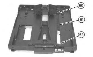
2. Install indicator band (61) and new tie-wraps (60). Install pin (62) in the bracket.
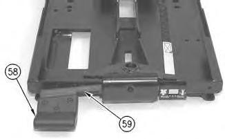
Illustration 2
g00288400
3. Install height adjustment lever (59) and handle (58). Install the key for the height adjustment lever.
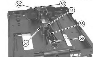
Illustration 3
g00288399
Note: Apply Tooling (b) to the roller shafts before installation.
4. Install arm assembly (55) and spring (57). Install roller (53) and two spacers. Install retaining ring (52). Install roller (54) and the pin. Install retaining ring (57). Make sure that the rollers do not bind.
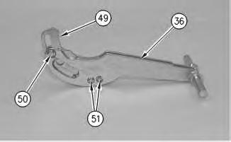
Illustration 4
g00288398
5. Install cam (49) in suspension arm (36). Install retaining rings (51) and (50) and the pins.
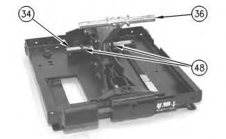
Illustration 5
g00288397
6. Install the shaft and suspension arm (36). Install two spacers (48) on shaft (34).
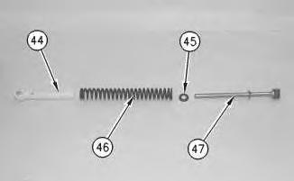
Illustration 6
g00288396
7. Assemble the spring assembly. Install rod assembly (47), retainer (45), spring (46), and guide bushing (44).
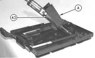
7
8. Attach Tool (A) to spring assembly (43), as shown. Slowly compress spring assembly (43). Use Tool (A) to install the spring assembly on the shaft as a unit.
9. Repeat Steps 7 and 8 for the spring assembly on the other side of the suspension arm.
8
9
This is the sample of the manual
Click on the download link for complete Manual
Note: Apply Tooling (B) to the roller shafts before installation.
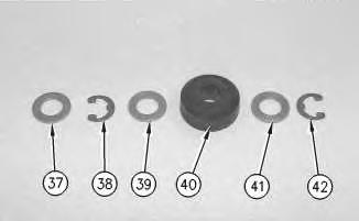
10. Install retaining rings (42) and (38), washers (41), (39) and (37), and rollers (40). Install roller assembly (35) on each side of suspension arm (36). Make sure that the rollers do not bind.
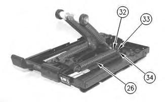
Illustration 10
g00288370
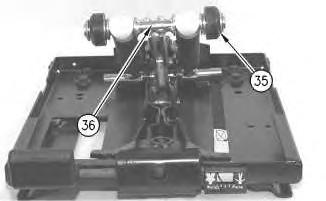
11. Install two springs (26) and plastic bearings (32) on height adjustment shaft (34). Install retaining ring (33) on each side of height adjustment shaft (34).
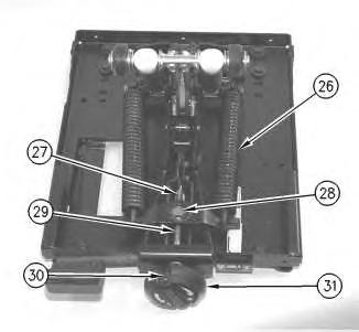
Illustration 11
g00288369
12. Install nut (28), weight adjustment screw (29), two races, the thrust bearing, weight adjustment knob (31) and pin (30). Turn weight adjustment knob (25) in the positive (+) direction to apply tension to springs (26). Install pin (27) in the end of weight adjustment screw (29).