

Previous Screen
Product: MOTOR GRADER
Model: 160H MOTOR GRADER ASD
Configuration: 160H Motor Grader
Disassembly and Assembly
(MACHINE) POWERED BY 3176C Engine
12H, 140H and 160H Motor Graders Power Train
Differential and Bevel Gear - Assemble
SMCS - 3256-016; 3258-016
Assembly Procedure Table 1
Note: Cleanliness is an important factor. Before assembly, all parts should be thoroughly cleaned in cleaning fluid. Allow the parts to air dry. Wiping cloths or rags should not be used to dry parts. Lint may be deposited on the parts which may cause later trouble. Inspect all parts. If any parts are worn or damaged, use new parts for replacement.
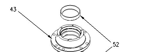
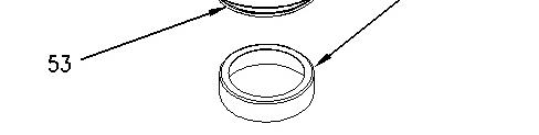
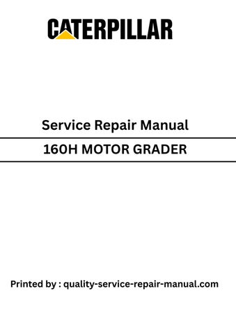
Illustration 1 g01000834
1. Lower the temperature of bearing cups (52) . Install bearing cups (52) in housing assembly (43) and Oring seal (53) .
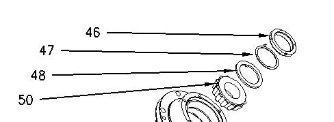
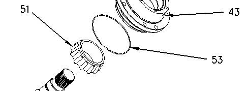

Illustration 2 g01001133
2. Raise the temperature of bearing cone (51) . Install bearing cone (51) on pinion (49) . Lubricate bearing cone (51) with SAE 30. Install housing (43) . Raise the temperature of bearing cone (50) . Install bearing cone (50) on pinion (49) . Lubricate bearing cone (50) with SAE 30. Install washer (48) , lock (47) , and locknut (46) . Use Tooling (H) to tighten locknut (46) , in order to achieve a rolling torque of 0.9 to 1.1 N·m (8 to 10 lb in).
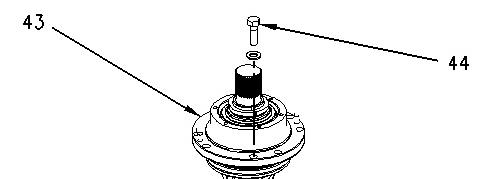
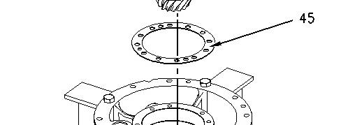

Illustration 3 g01001433
3. Install the original shims (45) . Install housing assembly (43) . Install bolts (44) . Tighten bolts (44) to a torque of 250 ± 25 N·m (184 ± 18 lb ft).
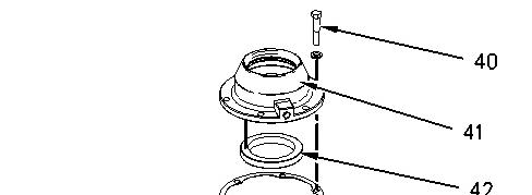
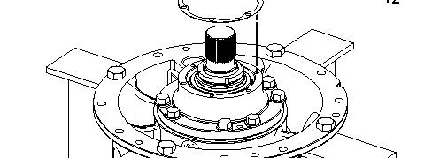
Illustration 4 g01000823
.
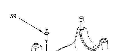
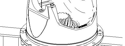
Illustration 5 g01000822
.
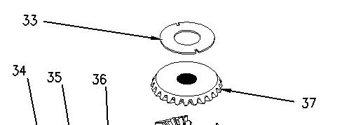
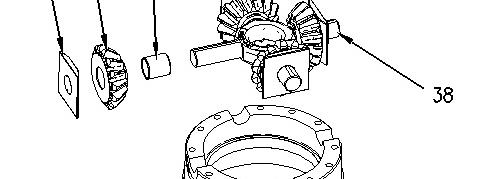

Illustration 6 g01000820
6. Install bearings (36) in pinions (35) .
Note: Bearings (36) must be flush with the face of pinions (35) .
7. Lubricate the shafts on spider (38) with Tooling (F) .
8. Install the pinion assemblies, spacers (34) , gear (37) , and washer (33) .
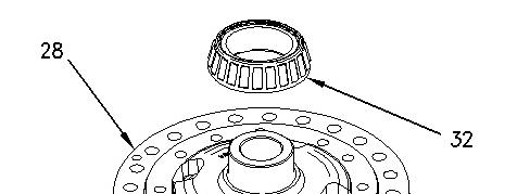

Illustration 7 g01000817
9. Raise the temperature of bearing cone (32) . Install bearing cone (32) in housing (28) .

This is the sample of the manual
Click on the download link for complete Manual
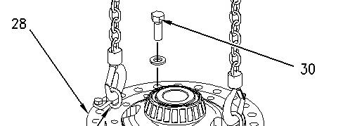
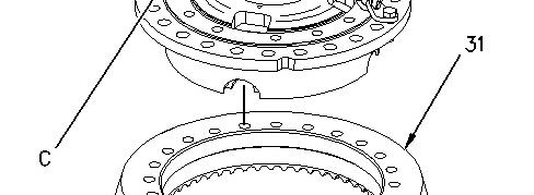
Illustration 8 g01001435
10. Attach Tooling (C) to housing (28) . Install housing (28) in gear (31) and install bolts (30) . Tighten bolts (30) to a torque of 270 ± 25 N·m (199 ± 18 lb ft).
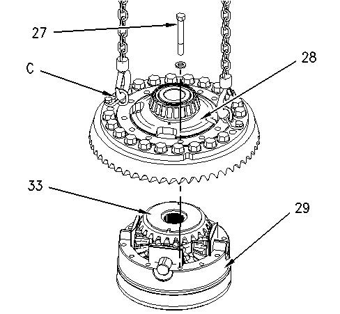
Illustration 9 g01001436
11. Install housing assembly (28) on housing (29) . Install bolts (27) . Tighten bolts (27) to a torque of 135 ± 15 N·m (100 ± 11 lb ft). The weight of housing assembly (28) is approximately 24 kg (52 lb).
Note: The dowels in housing (28) must align with the slots in washer (33) .
12. Remove Tooling (C) . Install remaining bolts (30) . Tighten bolts (30) to a torque of 270 ± 25 N·m (199 ± 18 lb ft).
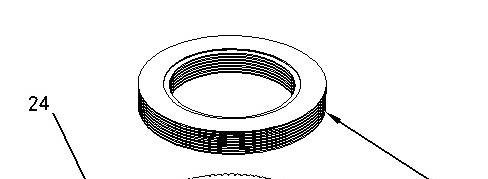
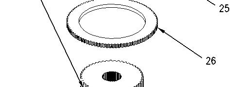

Illustration 10 g01000814
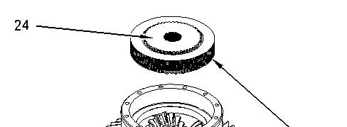
Illustration 11 g01000812
14. Install gear (24) with discs (25) .
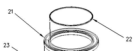

Illustration 12 g01000811
15. Lubricate seals (22) and (23) . Install seals (22) and (23) on piston (21) .
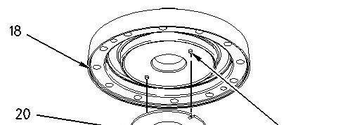
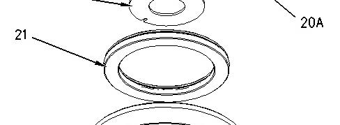

Illustration 13 g01001437
16. Install piston (21) , washer (20) , and the upper half of housing (18) .
Note: Dowel pins (20A) must align with the slots in washer (20) .
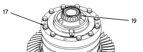

Illustration 14 g01001438
17. Raise the temperature of bearing cone (19) and install bearing cone (19) . Install bolts (17) . Tighten bolts (17) to a torque of 135 ± 15 N·m (100 ± 11 lb ft).
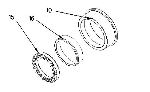
Illustration 15 g01001131
18. Install bearing cup (16) and nut (15) in cage (10) .
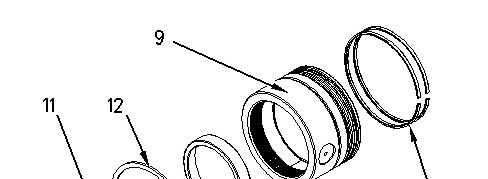
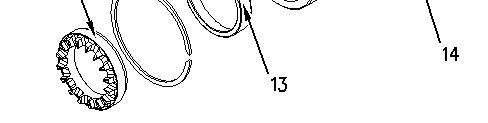
Illustration 16 g01000804
19. Install rings (14) , bearing cup (13) , ring (12) , and nut (11) on cage assembly (9) .
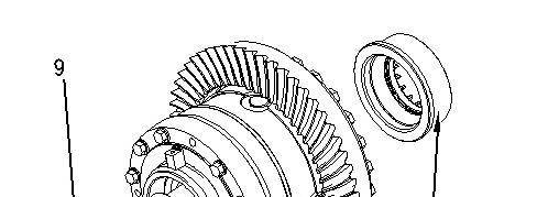
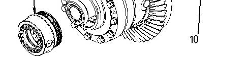
Illustration 17 g01000803
20. Install cage assemblies (9) and (10) .
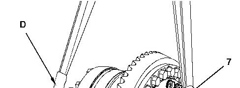


Illustration 18 g01290833
21. Attach a suitable lifting device and Tooling (D) to differential (8) .
22. Install differential (8) . The weight of differential (8) is approximately 182 kg (400 lb).
23. Install dowel (7) .
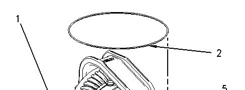
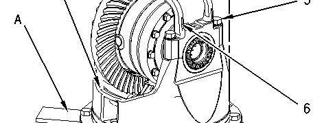
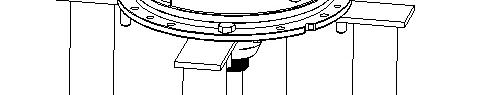
Illustration 19 g01001439
24. Attach differential and bevel gear (1) to Tooling (A) so the ring gear is facing upward.
25. Install cap (6) and bolts (5) . Tighten bolts (5) to a torque of 370 ± 50 N·m (273 ± 37 lb ft).
26. Install O-ring seal (2) .
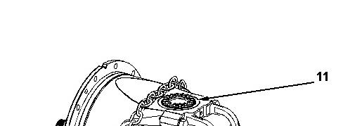
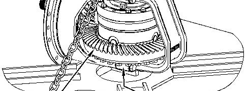
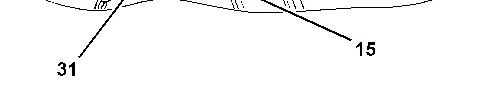
Illustration 20 g01291343
27. Rotate gear (31) . Adjust nut (15) to read zero and back off the nut to the closest lock position on nut (15) .
28. Rotate nut (11) until a heavy drag is felt. Loosen nut (11) and hand tighten nut (11) .
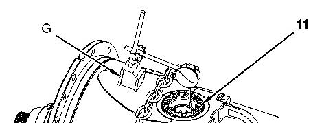
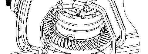
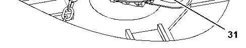
Illustration 21 g01291391
29. Install Tooling (G) .
Note: Be sure to preload the indicator.
30. Rotate nut (11) and rotate gear (31) .
Note: Preload the bearings by watching the indicator movement. The indicator should move 0.25 ± 0.05 mm (0.009 ± 0.002 inch).
31. Remove Tooling (G) .
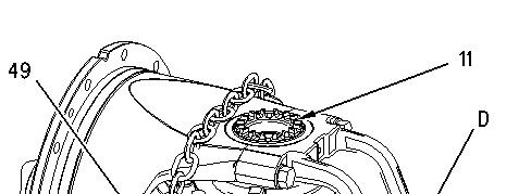
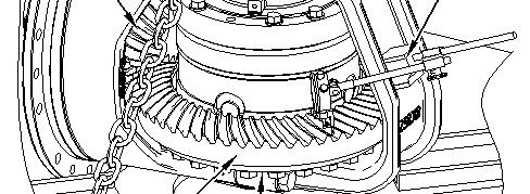
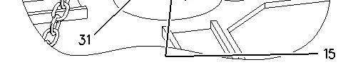
Illustration 22 g01001453
32. Install Tooling (G) . Check the backlash between gear (31) and pinion (49) . The backlash should be 0.25 + 0.10 mm - 0.07 mm (0.010 + 0.004 inch - 0.003 inch).
Note: Make the check at the heel of gear (31) in three places.
33. Advance and retract nuts (11) and (15) equal amounts. Maintain the bearing preload.
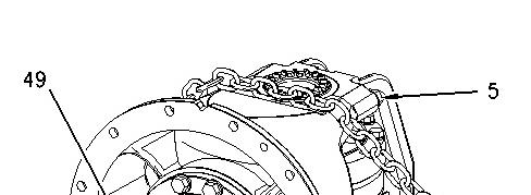
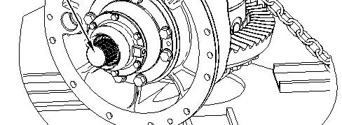

Illustration 23 g01001446
34. Check the rolling torque at pinion (49) . The rolling torque should be 2.2 ± .4 N·m (20 ± 4 lb in).
Note: The rolling torque for a used bearing should be 1.1 ± .2 N·m (10 ± 2 lb in).
35. Tighten bolts (5) to a torque of 370 ± 50 N·m (273 ± 37 lb ft).
36. The contact pattern between the pinion shaft and bevel gear must be checked. Apply marking compound to three teeth that are adjacent to the bevel gear.
37. Rotate the pinion shaft for several revolutions in one direction. Rotate the pinion shaft for several revolutions in the opposite direction. Turn the pinion shaft in one direction until the teeth that are marked can be viewed.

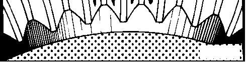
Illustration 24 g00101201
38. The correct area of tooth contact starts near the inside end of the teeth of the bevel gear. The maximum correct area of tooth contact is half the length of the teeth.
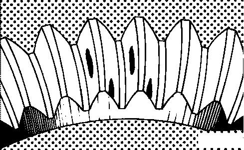
Illustration 25 g00101202
39. If the tooth contact looks like the contact pattern in Illustration 25, proceed to Step 41.
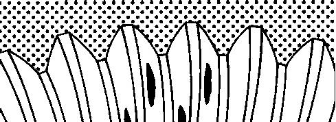

Illustration 26 g00101203
40. If the tooth contact looks like the contact pattern in Illustration 26, proceed to Step 43.
41. Remove some of the shims from the pinion housing. Recheck the backlash between the bevel gear and the pinion.
Note: Make sure that the backlash adjustment is correct before an adjustment is made to the area of tooth contact. Several adjustments to the backlash and tooth contact may be necessary to get the correct adjustments. Always remember that a change to gear clearance (backlash) will also change the gear contact. A change in gear contact will also change gear clearance (backlash).
42. Repeat Step 36 through Step 41 until the correct pattern is achieved.
43. Add some shims to the pinion housing. Recheck the backlash between the bevel gear and the pinion.
Note: Make sure that the backlash adjustment is correct before an adjustment is made to the area of tooth contact. Several adjustments to the backlash and tooth contact may be necessary to get the correct adjustments. Always remember that a change to gear clearance (backlash) will also change the gear contact. A change in gear contact will also change gear clearance (backlash).
44. Repeat Step 36 through Step 44 until the correct pattern is achieved.
45. After adjustments are made, remove the marking compound from the gears.
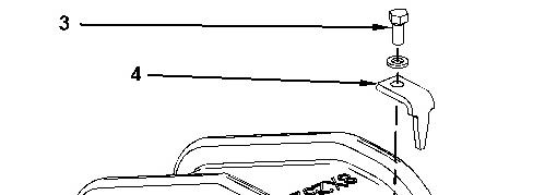
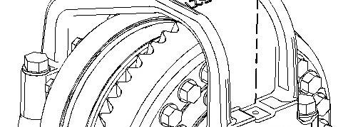
Illustration 27 g01291412
46. Install locks (4) and bolts (3) .
End By: Install the differential and the bevel gear. Refer to Disassembly and Assembly, "Differential and Bevel Gear - Install".
Copyright 1993 - 2020 Caterpillar Inc. All Rights Reserved. Private Network For SIS Licensees. Mon May 4 13:07:24 UTC+0530 2020
Previous Screen
Product: MOTOR GRADER
Model: 160H MOTOR GRADER ASD
Configuration: 160H Motor Grader ASD00001-UP (MACHINE) POWERED BY 3176C Engine
Disassembly and Assembly
12H, 140H and 160H Motor Graders Power Train
Differential and Bevel Gear - Disassemble
SMCS - 3256-015; 3258-015
Disassembly Procedure
Start By:
a. Remove the differential and the bevel gear. Refer to Disassembly and Assembly, "Differential and Bevel Gear - Remove".
Note: Cleanliness is an important factor. Before the disassembly procedure, the exterior of the component should be thoroughly cleaned. This will help to prevent dirt from entering the internal mechanism.
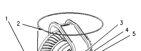
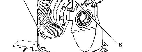
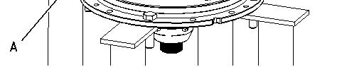
Illustration 1 g01000800
1. Attach differential and bevel gear (1) to Tooling (A).
2. Remove O-ring seal (2), bolts (3), locks (4), bolts (5), and cap (6).
Illustration 2 g01290833
3. Remove dowel (7).
4. Attach a suitable lifting device and Tooling (D) to differential (8).
5. Remove differential (8). The weight of differential (8) is approximately 182 kg (400 lb).
Illustration 3 g01000803
6. Remove cage assemblies (9) and (10).
Illustration 4 g01000804
7. Remove nut (11), ring (12), bearing cup (13), and rings (14) from cage (9).
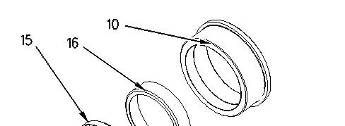

Illustration 5 g01001131
8. Remove nut (15) and bearing cup (16) from cage (10).

Illustration 6 g01000807
9. Remove bolts (17).
This is the sample of the manual
Click on the download link for complete Manual

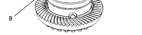
Illustration 7 g01000808
10. Use Tooling (B) to remove the upper half of housing (18). Remove bearing cone (19).
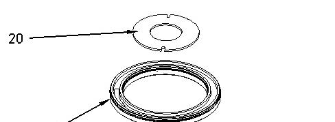
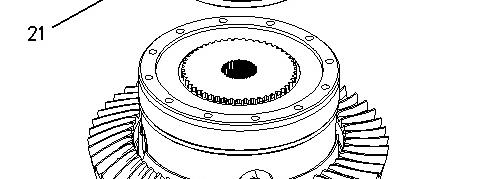

Illustration 8 g01000810