

Previous Screen
Product: MOTOR GRADER
Model: 160G MOTOR GRADER 4JD
Configuration: 160G MOTOR GRADER 4JD00001-00140 (MACHINE) POWERED BY 3306DI ENGINE
Disassembly and Assembly
3304B and 3306B Engines for Caterpillar Built Machines
Media Number -SENR5598-09 Publication Date -01/01/2013 Date Updated -25/01/2013
Fuel Filter Base - Remove and Install
SMCS - 1262-010
Removal Procedure
Table 1
Required Tools
A 2P-8250 Strap Wrench Assembly 1
NOTICE
Keep all parts clean from contaminants.
Contaminants may cause rapid wear and shortened component life.
NOTICE
Care must be taken to ensure that fluids are contained during performance of inspection, maintenance, testing, adjusting and repair of the machine. Be prepared to collect the fluid with suitable containers before opening any compartment or disassembling any component containing fluids.
Refer to Special Publication, NENG2500, "Caterpillar Tools and Shop Products Guide", for tools and supplies suitable to collect and contain fluids in Caterpillar machines.
Dispose of all fluids according to local regulations and mandates.
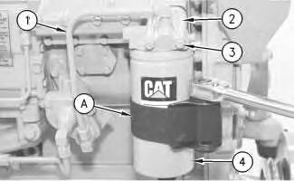
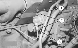
Illustration 1 g00468389
1. Use Tool (A) to remove fuel filter (4) .
2. Disconnect fuel line (1) from fuel filter base (2) .
3. Remove two bolts (3), the washers, fuel filter base (2) and the gasket from the fuel injection pump housing.
Installation Procedure
Table 2
Required Tools
NOTICE
Keep all parts clean from contaminants.
Contaminants may cause rapid wear and shortened component life.
Illustration 2
Note: Check the condition of the gaskets. If the gaskets are worn or damaged, use new parts for replacement.
1. Install the gasket, fuel filter base (2), the washers and two bolts (3) on the fuel injection pump housing.
2. Connect fuel line (1) to fuel filter base (2) .
3. Use Tool (A) to install fuel filter (4) . Copyright 1993 - 2025 Caterpillar Inc. All Rights Reserved. Private Network For SIS Licensees. Tue May 13 01:49:16 UTC+0530 2025
Previous Screen
Product: MOTOR GRADER
Model: 160G MOTOR GRADER 4JD
Configuration: 160G MOTOR GRADER 4JD00001-00140 (MACHINE) POWERED BY 3306DI ENGINE
Disassembly and Assembly
3304B and 3306B Engines for Caterpillar Built Machines
Media Number -SENR5598-09
Publication Date -01/01/2013 Date Updated -25/01/2013
Fuel Injection Lines - Remove and Install
SMCS - 1252-010
Removal Procedure
NOTICE
Keep all parts clean from contaminants.
Contaminants may cause rapid wear and shortened component life.
NOTICE
Care must be taken to ensure that fluids are contained during performance of inspection, maintenance, testing, adjusting and repair of the machine. Be prepared to collect the fluid with suitable containers before opening any compartment or disassembling any component containing fluids.
Refer to Special Publication, NENG2500, "Caterpillar Tools and Shop Products Guide", for tools and supplies suitable to collect and contain fluids in Caterpillar machines.
Dispose of all fluids according to local regulations and mandates.
1
1. Remove three bolts (1), (2) and (3) and the brackets from the fuel injection lines.

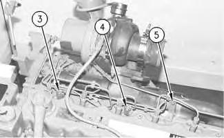
Illustration 2
g00448808
2. Disconnect six fuel injection line nuts (4) from the fuel injection pumps.
NOTICE
Do not allow the tops of the nozzles to turn while the fuel lines are loosened. The nozzles will be damaged if the top of the nozzle turns in the body. Defective fuel nozzles will damage the engine due to incorrect spray patterns.
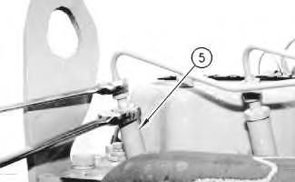
3. Hold the tops of fuel injector nozzles (5) with a wrench, as shown. Loosen the six fuel injection line nuts at fuel injector nozzles (4) .
4. Disconnect the fuel injection line nuts at the fuel injector nozzles and remove the fuel injection lines. Put caps and plugs on all openings immediately in order to prevent dirt from contaminating the fuel system.
Installation Procedure Table 1
5P-0144 Fuel Line Socket 1
NOTICE
Keep all parts clean from contaminants.
Contaminants may cause rapid wear and shortened component life.
NOTICE
Do not allow the tops of the nozzles to turn while the fuel lines are loosened. The nozzles will be damaged if the top of the nozzle turns in the body. Defective fuel nozzles will damage the engine due to incorrect spray patterns.
1. Remove the protective covers from the fuel line connections. Place the fuel injection lines in position on the engine. Tighten the fuel injection line nuts on the fuel injection pump and the fuel injector nozzles finger tight.
Note: The nozzle assembly must be supported with a wrench.
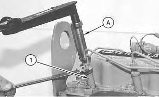
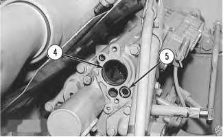
Illustration 4
2. Hold the tops of fuel injector nozzles (1) and use Tool (A) in order to tighten the fuel injection line nuts to a torque of 40 ± 7 N·m (30 ± 5 lb ft).
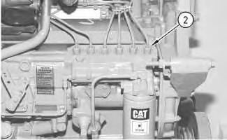
Illustration 5
3. Tighten six fuel injection line nuts (2) at the fuel injection pumps to a torque of 40 ± 7 N·m (30 ± 5 lb ft).
4. Install the brackets and three bolts (3), (4) and (5) that hold the fuel injection lines in position.
5. Prime the fuel system. Refer to the Operation and Maintenance Manual, "Fuel SystemPrime" topic (Maintenance Section). Copyright 1993 - 2025 Caterpillar Inc.
Rights Reserved.
Network For SIS Licensees.
Previous Screen
Product: MOTOR GRADER
Model: 160G MOTOR GRADER 4JD
Configuration: 160G MOTOR GRADER 4JD00001-00140 (MACHINE) POWERED BY 3306DI ENGINE
Disassembly and Assembly
3304B and 3306B Engines for Caterpillar Built Machines
Media Number -SENR5598-09
Publication Date -01/01/2013 Date Updated -25/01/2013
Fuel Ratio Control - Install
SMCS - 1278-012
Installation Procedure NOTICE
Keep all parts clean from contaminants. Contaminants may cause rapid wear and shortened component life.
This is the sample of the manual
Click on the download link for complete Manual
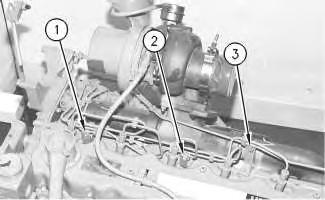
2
2. Put fuel ratio control (1) in position and engage the fuel ratio control with the lever assembly in the governor.
3. Install bolts (2) that hold the fuel ratio control and connect fuel pressure line (3) to fuel ratio control (1). Refer to Testing and Adjusting, "Fuel System" for more information on the adjustment procedure for the fuel ratio control.
Copyright 1993 - 2025 Caterpillar Inc. All Rights Reserved. Private Network For SIS Licensees. Tue May 13 01:49:47 UTC+0530 2025