

Product: MOTOR GRADER
Model: 14L MOTOR GRADER B94
Configuration: 14L Motor Grader - All Wheel Drive B9400001-UP (MACHINE) POWERED BY C9 Engine
Disassembly and Assembly
C9 Engines for Caterpillar Built Machines
Media Number -RENR9579-18
Air Inlet Heater - Install
SMCS - 1090-012
Installation Procedure Table 1
Publication Date -01/02/2015 Date Updated -11/02/2015
Keep all parts clean from contaminants.
Contaminants may cause rapid wear andshortened component life.
NOTICE
Care must be taken to ensure that fluids are containedduring performance of inspection, maintenance, testing, adjusting, and repair of the product. Be preparedto collect the fluid with suitable containers
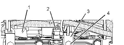
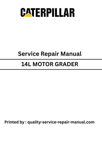
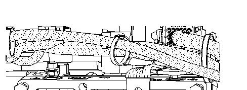
Illustration 2
2. Position air inlet elbow (5). Install bolts(4).
3. Connect ground strap (3) and install bolt (4).
4. Connect harness assembly (2).
5. Connect cable assembly (1).
Product: MOTOR GRADER
Model: 14L MOTOR GRADER B94
Configuration: 14L Motor Grader - All Wheel Drive B9400001-UP (MACHINE) POWERED BY C9 Engine
Disassembly and Assembly
C9 Engines for Caterpillar Built Machines
Media Number -RENR9579-18
Publication Date -01/02/2015
Date Updated -11/02/2015
i02312489
Air Inlet Heater - Remove
SMCS - 1090-011
Removal Procedure NOTICE
Keep all parts clean from contaminants.
Contaminants may cause rapid wear andshortened component life.
Illustration 1 g01158011
1. Disconnect cable assembly (1).
2. Disconnect harnessassembly (2).
3. Remove bolt (4) and disconnect ground strap (3).
4. Remove remaining bolts(4) and remove air inlet elbow (5).

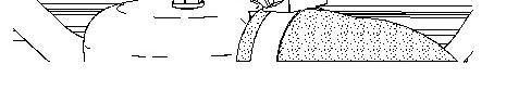
2 g01158012
5. Remove air inlet heater (6).
Copyright 1993 - 2020 Caterpillar Inc. All Rights Reserved. Private Network For SIS Licensees. Mon Aug 10 23:12:54 UTC+0530 2020
Product: MOTOR GRADER
Model: 14L MOTOR GRADER B94
Configuration: 14L Motor Grader - All Wheel Drive B9400001-UP (MACHINE) POWERED BY C9 Engine
Disassembly and Assembly
C9 Engines for Caterpillar Built Machines
Media Number -RENR9579-18
Publication Date -01/02/2015
Atmospheric Pressure Sensor - Remove and Install
SMCS - 1923-010
Date Updated -11/02/2015
i02304769
NOTICE
Keep all parts clean from contaminants.
Contaminants may cause rapid wear andshortened component life.
This is the sample of the manual
Click on the download link for complete Manual

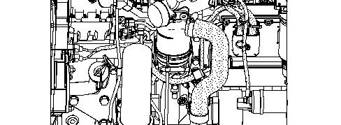

Illustration 1 g01154251
1. Disconnect harnessassembly (1) from atmospheric pressure sensor (2).
2. Remove atmospheric pressure sensor (2) and the O-ring seal.
Installation Procedure
NOTICE
Keep all parts clean from contaminants.
Contaminants may cause rapid wear andshortened component life.
Product: MOTOR GRADER
Model: 14L MOTOR GRADER B94
Configuration: 14L Motor Grader - All Wheel Drive B9400001-UP (MACHINE) POWERED BY C9 Engine
Disassembly and Assembly
C9 Engines for Caterpillar Built Machines
Media Number -RENR9579-18
Bearing Clearance - Check
SMCS - 1203-535; 1219-535
Measurement Procedure
Table 1 Required Tools
Plastic Gauge (Green)
to 0.076 mm
to 0.003 inch)
Plastic Gauge (Red)
to 0.152 mm (0.002 to 0.006 inch)
Plastic Gauge (Blue)
to 0.229 mm (0.004 to 0.009 inch)
Plastic Gauge (Yellow) 0.230 to 0.510 mm (0.009 to 0.020 inch)
Date -01/02/2015
Note: Plastic gauge may not be necessary when the engine is in the chassis.
Updated -11/02/2015
Keep all parts clean from contaminants.
Contaminants may cause rapid wear andshortened component life.
Note: Cat does not recommend the checking of the actual bearing clearancesparticularly on small engines. This is because of the possibility of obtaining inaccurate resultsand the possibility of damaging the bearing or the journal surfaces. Each Cat engine bearing is quality checked for specific wall thickness.
Note: The measurements should be within specifications and the correct bearings should be used. If the crankshaft journals and the bores for the block and the rods were measured during disassembly, no further checks are necessary. However, if the technician still wants to measure the bearing clearances, Tooling (A) is an acceptable method. Tooling (A) is less accurate on journals with small diameters if clearances are less than 0.10 mm (0.004 inch).
NOTICE
Lead wire, shim stock or a dial bore gauge can damage the bearing surfaces.
The technician must be very careful to use Tooling (A) correctly. The following points must be remembered:
• Ensure that the backs of the bearings and the bores are clean and dry.
• Ensure that the bearing locking tabs are properly seated in the tab grooves.
• The crankshaft must be free of oil at the contact pointsof Tooling (A).
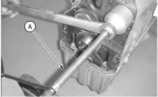
1. Put a piece of Tooling (A) on the crown of the bearing that is in the cap.
Note: Do not allow Tooling (A) to extend over the edge of the bearing.
2. Use the correct torque-turn specifications in order to install the bearing cap. Do not use an impact wrench. Be careful not to dislodge the bearing when the cap is installed.
Note: Do not turn the crankshaft when Tooling (A) is installed.
3. Carefully remove the cap, but do not remove Tooling (A). Measure the width of Tooling (A) while Tooling (A) is in the bearing cap or on the crankshaft journal. Refer to Illustration 1.
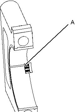

Illustration 1 g01152855
TypicalExample
4. Remove all of Tooling (A) before you install the bearing cap.
Note: When Tooling (A) is used, the readings can sometimes be unclear. For example, all partsof Tooling (A) are not the same width. Measure the major width in order to ensure that the partsare within the specification range. Refer to Specifications Manual, "Connecting Rod Bearing Journal" and SpecificationsManual, "Main Bearing Journal" for the correct clearances.
Copyright 1993 - 2020 Caterpillar Inc. All Rights Reserved. Private Network For SIS Licensees. Mon Aug 10 23:26:56 UTC+0530 2020
Product: MOTOR GRADER
Model: 14L MOTOR GRADER B94
Configuration: 14L Motor Grader - All Wheel Drive B9400001-UP (MACHINE) POWERED BY C9 Engine
Disassembly and Assembly
C9 Engines for Caterpillar Built Machines
Media Number -RENR9579-18
Camshaft - Install
SMCS - 1210-012
Installation Procedure Table 1 Required Tools
Publication Date -01/02/2015
Date Updated -11/02/2015
Keep all parts clean from contaminants.
Contaminants may cause rapid wear andshortened component life.
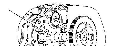

1 g03356215
NOTICE
Do not damage the lobesor the bearings when the camshaft is removed or installed.
Note: During the installation of the camshaft, rotate the camshaft in both directions in order to prevent binding in the camshaft bearing bores.
1. Lubricate the camshaft lobes and the valve lifter bore with a 50/50 mixture of Tooling (B). Apply clean engine oil on the camshaft bearing journals. Carefully install camshaft (10) in the cylinder block.

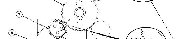
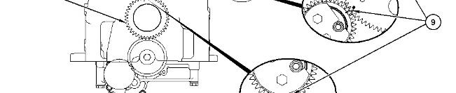
Illustration 2
(5) Gear for the high-pressure fuel pump
(6) Camshaft gear
(7) Idler gear
(8) Crankshaft gear
(9) Timing marks
g03356207
NOTICE
When installing the camshaft, make sure the number one cylinder isat top center of the compression stroke withthe timing bolt installed in the flywheel. The camshaft timing is very important. The timing mark on the camshaft drive gear must line up with the timing mark on the idler gear. Refer to the Specifications Manual for more information.
2. Correct fuel injection timing and correct valve mechanism operation is determined by properly timing crankshaft gear (8) and camshaft gear (6) to idler gear (7). Also, high-pressure fuel pump gear (5) must be timed to camshaft gear (6). During installation of the front gear, timing marks (9) on idler gear (7)
must be in alignment with the timing marks on crankshaft gear (8) and the timing marks on camshaft gear (6). The "0" mark on camshaft gear (6) must align with the timing mark on idler gear (7). The "V" mark on camshaft gear (6) must align with the "V" mark on fuel pump gear (5).


Illustration 3 g01032348
3. Install thrust plate (4) and bolts (3).
4. The maximum permissible end play for a worn camshaft is0.46 mm (0.018 inch). The maximum permissible end play for a new camshaft is0.13 ± 0.08 mm (0.005 ± 0.003 inch).
5. Use Tooling (A) to position the valve liftersin the cylinder block.
6. Calibrate the speed/timing sensor. Refer to Troubleshooting, "Engine Speed/Timing SensorCalibrate".
End By:
a. Install the front cover. Refer to Disassembly and Assembly, "Front Cover - Install".
b. Install the rocker arm and the shaft. Refer to Disassembly and Assembly, "Rocker Arm and ShaftInstall".
Product: MOTOR GRADER
Model: 14L MOTOR GRADER B94
Configuration: 14L Motor Grader - All Wheel Drive B9400001-UP (MACHINE) POWERED BY C9 Engine
Disassembly and Assembly
C9 Engines for Caterpillar Built Machines
Media Number -RENR9579-18 Publication Date -01/02/2015 Date Updated -11/02/2015
i02274059
Camshaft - Remove
SMCS - 1210-011
Removal Procedure Table 1 Required Tools
Start By:
a. Remove the rocker arm and the shaft. Refer to Disassembly and Assembly, "Rocker Arm and ShaftRemove".
b. Remove the front cover. Refer to Disassembly and Assembly, "Front Cover - Remove".
NOTICE
Keep all parts clean from contaminants.
Contaminants may cause rapid wear andshortened component life.
1. Use Tooling (A) to reposition the valve lifters out of the way of the camshaft.
2. Set the No. 1 piston to top center on the compression stroke. Refer to Testing and Adjusting, "Finding Top Center Position for No. 1 Piston".
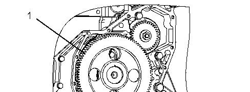

Illustration 1 g01032348
3. Ensure that the timing marks on camshaft gear (1) and idler gear (2) are aligned.
4. Remove bolts (3) and thrust plate (4) from the cylinder block.


Illustration 2 g01032349
Do not damage the lobesor the bearings when the camshaft is removed or installed.
5. Remove camshaft (5) from the cylinder block.
Copyright 1993 - 2020 Caterpillar Inc. All Rights Reserved. Private Network For SIS Licensees. Mon Aug 10 23:22:42 UTC+0530 2020
Product: MOTOR GRADER
Model: 14L MOTOR GRADER B94
Configuration: 14L Motor Grader - All Wheel Drive B9400001-UP (MACHINE) POWERED BY C9 Engine
Disassembly and Assembly
C9 Engines for Caterpillar Built Machines
Media Number -RENR9579-18
Publication Date -01/02/2015
Camshaft Bearings - Install
SMCS - 1211-012
Installation Procedure
Table 1
RequiredTools
Date Updated -11/02/2015
NOTICE
Keep all parts clean from contaminants.
Contaminants may cause rapid wear andshortened component life.
NOTICE
Camshaft bearings must be installed into their correct position. Failure to do so will result inengine damage.
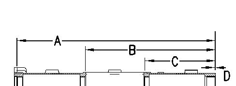
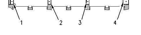
Illustration 1 g00884735
1. Refer to Illustration 1 for the locations of the bearings.
(1) Installation Dimension (A) for bearing (1) ... 816.5 ±0.8 mm (32.15 ± 0.03 inch)
(2) Installation Dimension (B) for bearing (2) ... 536.5 ± 0.8 mm (21.12 ± 0.03 inch)
(3) Installation Dimension (C) for bearing (3) ... 294.5 ± 0.8 mm (11.59 ± 0.03 inch)
(4) Installation Dimension (D) for bearing (4) ... 0.50 ±0.25 mm (0.020 ± 0.010 inch)
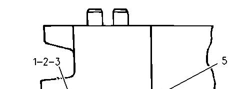
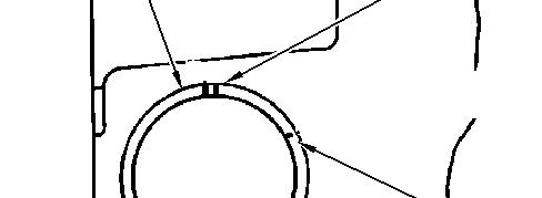
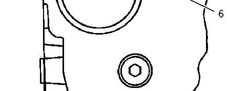

Illustration 2 g00884754
2. Use Tooling (A) to install bearings (1), (2), and (3) that are behind the front bearing. Install the bearings to the proper depths. Refer to Illustration 1 and refer to Step 1. Orient the bearings so that oil holes (5) are located at the topsof the bores and joints (6) are positioned, as shown.
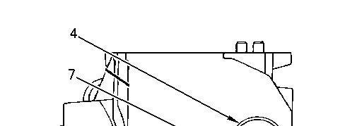
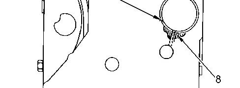
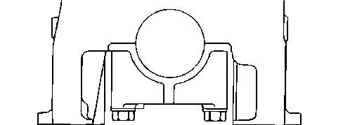

Illustration 3 g00884758
3. Install front bearing (4). Carefully locate oil hole (8) at the oil gallery. Orient joint (7), as shown.
End By:
a. Install the flywheel housing. Refer to Disassembly and Assembly, "Flywheel Housing - Remove and Install".
b. Install the camshaft. Refer to Disassembly and Assembly, "Camshaft - Install".
Product: MOTOR GRADER
Model: 14L MOTOR GRADER B94
Configuration: 14L Motor Grader - All Wheel Drive B9400001-UP (MACHINE) POWERED BY C9 Engine
Disassembly and Assembly
C9 Engines for Caterpillar Built Machines
Media Number -RENR9579-18
Publication Date -01/02/2015 Date Updated -11/02/2015
Camshaft Bearings - Remove
SMCS - 1211-011
Removal Procedure
Table 1
Required Tools
Start By:
a. Remove the camshaft. Refer to Disassembly and Assembly, "Camshaft - Remove".
b. Remove the flywheel housing. Refer to Disassembly and Assembly, "Flywheel Housing- Remove and Install".
Note: Note the oil hole orientation in each camshaft bearing prior to removal for assembly purposes.
NOTICE
Keep all parts clean from contaminants.
Contaminants may cause rapid wear andshortened component life.
This is the sample of the manual
Click on the download link for complete Manual
Care must be taken to ensure that fluids are containedduring performance of inspection, maintenance, testing, adjusting, and repair of the product. Be preparedto collect the fluid with suitable containers before opening any compartment or disassembling any component containing fluids.
Refer to Special Publication, NENG2500, "Dealer Service Tool Catalog" for tools andsupplies suitable to collect and contain fluids on Cat® products.
Dispose of all fluids according to local regulations and mandates.
1993 - 2020 Caterpillar Inc.