

Product: MOTOR GRADER
Model: 14H MOTOR GRADER ASE
Configuration: 14H Motor Grader ASE00001-UP (MACHINE) POWERED BY 3176C Engine
Disassembly and Assembly
Flexxaire Fan
Control System - Remove and Install
SMCS -1356-010-YC
General Installation
Installation of the Mark I Control System

i01739978
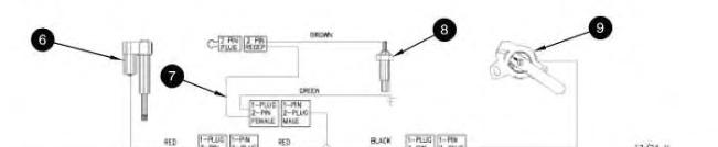
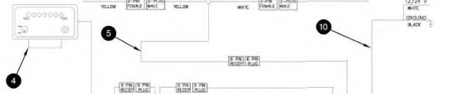
Mark IControl System
(1) MarkI controlbox
(2) AUTO-purge timer
(3) Cable for remote display
(4) Remote display
(5) Pigtail
(6) Actuator
(7) Temperature and ground cable
(8) Temperature sensor
(9) Positionsensor
(10) Power cable
1. Mountcontrol box (1) in the operator's compartment. The mounting location should meetthefollowing criteria:
Minimal debris and vibration
Safe fromwater that is high pressure
Accessiblefor futureadjustmentsor changes in setup
Thecontrol box should be mounted in avertical position, and vibration mounts that are supplied with the controller should be installed.
2. AUTO-purge timer (2) islocated near control box (1). Connecttheend of thecable for AUTO-purge timer (2) to theplug end of the cablefor the AUTO-purge timer on control box (1).
3. Cable for remote display (3) may not be required for all installations. Connecttheend of thecable for remote display (3) to the plug end of AUTO-purgetimer (2). Connect the plug end ofcable for remote display (3) into theend of the pigtail for remote display (4).
4. Mountremotedisplay (4) on the dash or another convenient location. The remotedisplay should be visible and accessible to the operator. Connect the end of the cable for remote display (4) to theplug end of the cablefor remotedisplay (3).
5. Connect theend of pigtail (5) to theplug end of the cablefor control box (1). Pigtail (5) splitsinto a harness with threeconnectors. Oneend goes to actuator (6). One end goes to temperaturesensor (8). One end goes to position sensor (9).
6. Thefollowing steps arefor installation of actuator (6):
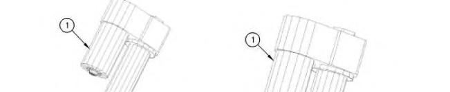
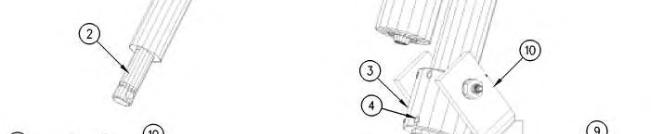
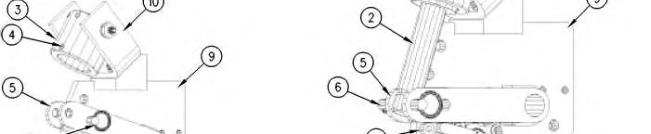
Illustration 2 g00592444
(1) Actuator
(2) Actuator rod
(3) Actuator collar
(4) Setscrew
(5) Operator fork
(6) Hitch pin
(7) Mechanical stop
(8) Positionsensor
(9) Alignmentplate
(10) Actuatorclevis
a. Remove hitch pin (6).
b. Position operator fork (5) against mechanical stop (7).
c. Manually turn actuator rod (2) outward untiltherod is fully extended. When therod reaches theend of travel, theactuator motor can befelt turning.
d. Retract actuator rod (2) by therotating actuator rod by 180 degrees. Theactuator motor should not turn.
e. Slide actuator (1) through actuator collar (3). Verify thattheactuator collar is oriented so that setscrews (4) arefacing away fromactuator clevis (10).
f. Retracting actuator rod (2) by 1/4 turn may be required in order to line up thehole in actuator rod (2) with the hole in operator fork (5).
g. Insert hitch pin (6) through operator fork (5) and actuator rod (2).
h. Verify that operator fork (5)is againstmechanicalstop (7). Makesure that the actuator motor is oriented in the correct position. Theactuator motor must be clear of obstructions. Rotatetheactuator in the collar prior to tightening setscrews (4).
i. Apply 9S-3263 Thread Lock Compound to setscrews (4) and install thesetscrews.Tighten the setscrew to a torque of 16 N·m(12 lb ft).
Note: Do not tighten setscrews more than 1.5 threads belowthesurface.
j. Connect theend of the cable for theactuator to the red and yellowplug of pigtail(5).
7. Connect theend of temperature and ground cable (7) to theplug with green and black wires of pigtail (5). Theground wire (green) is secured with abolt that threads in to the support arm of the fan assembly. The brown lead wire is connected to thetop of temperature sensor (8).
8. Thread temperaturesensor (8) into theengine block. An area that is close to the water temperature regulator isrecommended. Temperature sensor (8) comes with three thread adapters. Thebrown lead wire of temperature and ground cable (7) connects to the top of temperaturesensor (8).

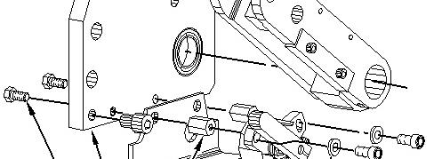
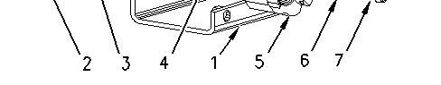
Illustration 3
(1) Mountingbracket for the positionsensor
(2) Bolt
(3) Alignmentplate
(4) Mountingnut for the positionsensor
(5) Positionsensor
(6) Washer
(7) Capscrew
g00918804
9. Thefollowing steps arefor installation of position sensor (9):
a. Place mounting bracket (1) for theposition sensor against alignment plate (3).
b. Thread bolt (2) into mounting nut (4) for the position sensor through alignmentplate(3) and position sensor mounting bracket (1). Tighten bolt (2) to atorque of 16.3 N·m (12.0 lb ft).
c. Place position sensor (5) in the correct location.
d. Put washer (6) on capscrew (7). Thread capscrew(7) into mounting nut(4) for the position sensor through position sensor (5).
e. Connect theplug end of thecable for position sensor (5) to theend of the pigtail.
10. Connect theplug end of power cable (10) to the end of thepower cablefor thecontrol box.
White wire - This wire connectsto a10 Amp fuse or to a circuit breaker. The powersource that is being used must allow power to thecontrol box when the engineis notrunning.
Black wire- This wireconnects to the main disconnect or a different ground location.
Installation of the Mark III Control System
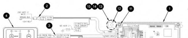
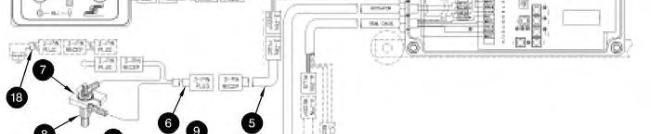
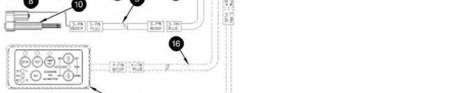
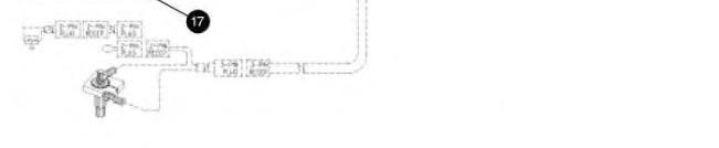
Illustration 4 g00573394
Mark IIIcontrol system
(1) MarkIII controlbox
(2) Power cable
(3) Extension cable for remote display
(4) Remote display
(5) Extension cable for temperature sensor
(6) Cable for temperature sensor
(7) Groundcollar
(8) Temperature sensor
(9) Extension cable for actuator
(10) Actuator
(11) Screw
(12) Mounting bracket
(13) Vibration mount
(14) Washer
(15) Nut
(16) Cable for remote calibrator
(17) Remote calibrator
(18) Pressure switch
1. Mountcontrol box (1) in the operator's compartment. The mounting location should meetthefollowing criteria:
Minimal debris and vibration
An areathatis away from high pressurewashes
Accessiblefor futureadjustmentsand changes in setup
Thecontrol box should be mounted in avertical position and the vibration mounts that are supplied with the control box should be installed.
2. Install temperature sensor (8) with theNPT bushing that is supplied. Thesensor should beinstalled in the water jacket of the engine. Themost preferablelocation for thetemperaturesensor is near the coolant temperatureregulator. Thiswill allow thesensor to sense maximum water temperature.
3. Routeextension cable for temperaturesensor (5) from the control box to the temperaturesensor.Connect cablefor temperature sensor (6) to extension cable (5).Connect the black wire to the ground collar. Install the ground collar around the hex portion of the temperature sensor and tighten theclamping screw. Connect the whitewire to thetop of thetemperature sensor.
4. Routeextension cable for actuator (9)fromthe control box to the actuator.
5. Connect power cable (2).
Red wire- Thiswire connects to a10 Amp fuse or to acircuitbreaker. The connection should bemadeto acircuit that isisolated during operation of the starter. This circuitshould notbepowered when the ignition key is in theOFF position.
Black wire- This wireconnects to the main disconnect or a stable ground location.
6. Mountremotedisplay (4) on the dash or another convenient location. The remotedisplay should be visible and accessible to the operator. Connect the remotedisplay to the controlbox with an extension cable for
This is the sample of the manual
Click on the download link for complete Manual
remote display (3). If it is notpracticalto mount the remotedisplay in theoperator's compartment, the display should bemounted in an enclosed area that will not be exposed to the elements. The display is not required for operation of the controlbox.
7. Applications that use the radiator fan to cool the A/C condenser core should use pressureswitch (18). The pressure switch should be installed on the high pressuresideof the compressor.Remove the jumper wire from cablefor temperature sensor (6) and plug in pressureswitch (18). When the condenser core reaches a set pressure, the fan is put into full pitch in order to cool thecondenser core.
8. Thefollowing steps arefor installation of actuator (10):
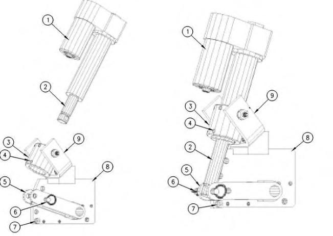
Illustration 5
(1) Actuator
(2) Actuator rod
(3) Actuator collar
(4) Setscrew
(5) Operator fork
(6) Hitch pin
(7) Mechanical stop
(8) Alignmentplate
(9) Actuator clevis
a. Remove hitch pin (6).
b. Position operator fork (5) against mechanical stop (7).
c. Manually turn actuator rod (2) outward untiltherod is fully extended. When therod reaches theend of travel, theactuator motor can befelt turning.
d. Retract actuator rod (2) by rotating actuator rod (2) by 180 degrees. The actuator motor should not turn.
e. Slide actuator (1) through actuator collar (3). Verify thattheactuator collar is oriented so that setscrews (4) arefacing away fromactuator clevis (10).
f. Retracting actuator rod (2) by 1/4 turn may be required in order to line up thehole in actuator rod (2) with the hole in operator fork (5).
g. Insert hitch pin (6) through operator fork (5) and actuator rod (2).
h. Verify that operator fork (5)is againstmechanicalstop (7). Makesure that the actuator motor is oriented in the correct position. Theactuator motor must be clear of obstructions. Rotatetheactuator in the collar prior to tightening setscrews (4).
i. Apply 9S-3263 Thread Lock Compound to setscrews (4) and install thesetscrews.Tighten the setscrew to a torque of 16.3 N·m (12.0 lb ft).
Note: Do not tighten setscrews more than 1.5 threads belowthesurface.
9. Connect theend of the cable for theactuator to the plug end of theextension cable.
Installation of Blaze Blocker
This featureis integral to thecontrolbox. Therequired connector is part of the harness from the controlbox. The connector will receive thesignal from thefiresuppression system.
Note: Before the circuit is tested, besurethat the canisters for the fire suppression system are disconnected in order to prevent thecanisters from discharging when the circuit is energized.Reconnectthecanisters after thetest of thecircuit is complete.
1. Locate the control box.
2. Determinewhether the firesuppression system ismanual or automatic.
3. Followtheappropriate procedure:
a. Manual Fire Suppression System
Install aswitch that is normally open near thefire suppression plunger.
Connect a 16 gauge wire from the common terminal of theswitch to ground.
Connect a 16 gauge wire from the other pole of theswitch into pin 1 of a deutsche connector. Thelength of the signal wirewill depend on the distance from the switch to theconnector on the control box. Pin 2 of thedeutsche connector is left empty.
Connect theplug from the switch to the receptacleon the controller.
Apply power to thecontrol box and turn the switch ON. Thecontrolbox will placethe fan into the NEUTRALposition. The "PUSH" light and the"PULL" lighton the remotedisplay will be flashing as wellas the T1 light and T2 light insidethecontrolbox. This indicates that the switch is wired properly and thatblaze blocker is on.
Move the switch to the OFF position in order to resumenormaloperation.
When a fire isobserved, the operator should flip the switch first. Then, the operator should activatethe fire suppression system.
b. AutomaticFireSuppression System
Locate the warning alarm relay circuit. This circuit will activatea warning relay on the fire suppression system. This indicates that a fire has been detected.
Connect a 16 gauge wire from the common terminal of therelay to ground.
Connect a 16 gauge wire from the other pole of therelay into pin 1 of a deutscheconnector. Thelength of the signal wirewill depend on the distance from the switch to theconnector on the control box. Pin 2 of thedeutsche connector is left empty.
Connect theplug from the relay to thereceptacle on thecontroller.
When therelay isenergized, the control box willplace the fan into the NEUTRAL position. The"PUSH" light and the"PULL" light on the remote display will be flashing as well as the T1 light and T2 light insidethe controlbox. This indicates that the switch is wired properly and that blaze blocker is on.
1993 - 2020 Caterpillar Inc.

Product: MOTOR GRADER
Model: 14H MOTOR GRADER ASE
Configuration: 14H Motor Grader ASE00001-UP (MACHINE) POWERED BY 3176C Engine
Disassembly and Assembly
Flexxaire Fan
i06636599
Hydraulic Actuated Fan - Assemble
SMCS - 1356-016-HR
Preliminary Fan Assembly
Note: Refer to the Service Manual Disassembly and Assembly (Engine Supplement), "Reversible Fan - Assemble"for the Track Feller Buncher machines only on the assembly procedure.
Note: Before you proceed, ensure that you know the correct model of the hydraulic actuated fan. Refer to Operation and Maintenance Manual, "Model View Illustrations" to identify the model of the fan.
1. Clean all surfaces and threads prior to assembly.
2. Make sure that all the parts are present for the assembly.
3. To ease assembly, lubricate all the seals and the O-rings as you assemble the fan.
Note: Unless the instructions state otherwise, do NOT apply Loctite or any equivalent adhesives to any of the fasteners that contact aluminum parts.
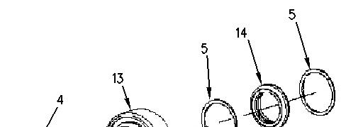
Main Shaft - Assemble
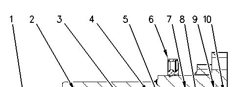
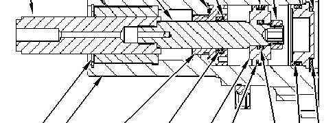
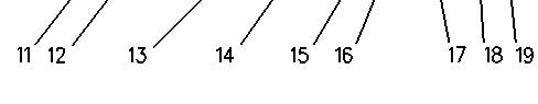
Illustration 1 g00906033
(1) Hexthrough shaft
(2) Bushing
(3) Rodshaft
(4) O-ring
(5) Backup ring
(6) Seal
(7) External Seal
(8) Hexnut
(9) Backup ring
(10) End cap
(11) Bushing snap ring
(12) Main shaft
(13) Seal Retainer
(14) Internal Seal
(15) Piston
(16) Backup rings
(17) O-ring
(18) O-ring
(19) Snapring
For reference, Illustration 1 picturesa crosssection view of the main shaft that iscompletely assembled.
1. Position the main shaft in a vise.
Note: If an extension is used on the main shaft, apply a few dropsof 4C-9506 Retaining Compound to the threads of the extension. Thread the extension and tighten the extension to a torque of 34 N·m (25 lb ft).
2. Clean the inside of the main shaft and seal retainer of all possible debris with 138-8441 Brake Cleaner.

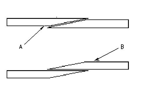
(A) The correct positionfor the backuprings (B) The incorrect positionfor the backup rings
3. Place internal seal (14) into the seal retainer (13).
4. Insert both backup rings (5) on either side of the internal seal (13).
Note: Make sure that the endsof the backup rings are enclosed on each other properly. See Illustration 3 for the correct positioning of the ends of the backup rings.
5. Apply a small amount of grease on O-ring (4) to hold the O-ring in place. Place O-ring (4) in the O-ring groove of seal retainer (13).
6. Apply a thin coating of oil onto the inside of the internal seal.
7. Thread seal retainer (13) into the rear of main shaft (12).
Note: Do NOT apply Loctite or equivalent adhesives to the threads of the seal retainer.
8. Use Snap-On S6183 Socket to tighten the seal retainer to a torque of (13) to 34 N·m (25 lb ft).
9. Slide rod shaft (3) through seal retainer (13) until the end of the hex through shaft (1) comesto rest against seal retainer (13). Repeat this step for the various sides of the hex through shaft until you find a position that gives no resistance except for the resistance from the seal.
Note: Use a finger on the other side of the main shaft to help guide the rod shaft past the seal retainer.
Note: When you are sliding the rod shaft past seal retainer (13), be careful not to damage the internal seal and/or the backup rings.
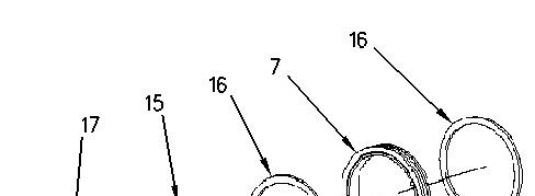
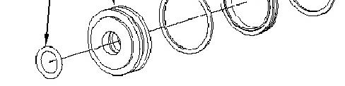
Illustration 4 g00906297
10. Place external seal (7) onto piston (15).
11. Insert both backup rings (16) on either side of external seal (7).
Note: Make sure that the endsof the backup rings are enclosed on each other properly. See Illustration 3 for the correct positioning of the ends of the backup rings.
12. Place internal O-ring (17) into the groove on piston (15).
13. Apply a thin coating of oil onto external seal (7) and onto O-ring (17) of the piston.
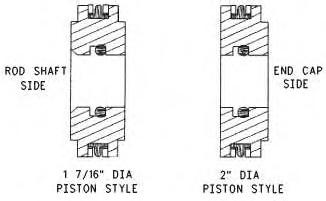
Illustration 5
g00906300
14. Push piston (15) into the rear of main shaft (12) and onto the end of rod shaft (3) until the piston restsagainst the shoulder of the rod shaft.
Note: Some designs have a spacer that needs to be installed. The spacer is located between seal retainer (13) and the piston (15).
Note: The orientation of the piston prior to installation is critical. There are two different styles of piston that are used. See Illustration 5 for the proper orientation.
Note: Be careful when you slide piston (15) into main shaft (12) and onto the end of rod shaft (3). Do not damage external seal (7), backup rings (16), or O-ring (17).
15. Apply 9S-3263 Thread Lock Compound to the threads of hex nut (8).
16. Thread hex nut (8) onto rod shaft (3) and tighten the hex nut to a torque of 34 N·m (25 lb ft).
Note: Slide the shafts and the piston in and out to make sure that the resistance isslight.
17. Push piston (15) until the piston comes to rest against seal retainer (13).
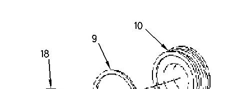

Illustration 6 g00906341
18. Install backup ring (9) onto end cap (10).
Note: Make sure that the endsof the backup rings are enclosed on each other properly. See Illustration 3 for the correct positioning of the ends of the backup rings.
19. Install O-ring (18) onto end cap (10).
20. Lubricate the O-ring with a thin coating of oil.
21. Insert end cap (10) into the rear of main shaft (12).
22. Insert rear snap ring (19) into main shaft (12) to secure end cap (10). Be sure that snap ring (19) isproperly seated in the main shaft.
Note: The square edge on the snap ring must be facing outward and the edge must be properly seated. If an extension to the main shaft is used in the assembly, install the snap ring into the main shaft extension.
23. Remove the main shaft from the vise.
Mounting Main Shaft onto Mounting Bracket

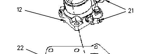

Illustration 7 g00906423
1. Thread hydraulic connectors (21) onto main shaft (12) by hand to correctly orient the connectors.
Note: If information on the orientation of the connectorsisrequired, contact Flexxaire at (780) 930-6832.
2. Mount the fan mounting bracket into a horizontal position, onto a vertical mounting stand, or onto a vise.
3. Place main shaft (12) onto fan mounting bracket (22).
Note: The proper orientation of the main shaft onto the fan mounting bracket must be kept when you assemble these partstogether. This will keep the centerline of the fan assembly and the height of the engine mounting correct, and the hydraulic lines will connect correctly.
4. Apply 9S-3263 Thread Lock Compound onto the threads of fastener (20).
5. Install fastener (20) into fan mounting bracket (22) and tighten to the specification.
6. Secure hydraulic connectors(21) to main shaft (12), but do NOT tighten the connectors excessively.
7. If necessary, install the hydraulic hoses on the fan.
Main Shaft - Pressure Check
Performing a pressure check on the main shaft will ensure that all the sealsare properly seated. If you do not perform a pressure check, several problems can arise. Such problemsinclude leaking hydraulic fluid and inadequate hydraulic pressure that is needed to change the pitch of the blades.
1. Connect a hydraulic source with a shutoff valve and a hydraulic pressure gauge between the pressure source and the fan. Repeat this step on both lines. Ensure that the shutoff valve is in between the pressure source and the gauge.
Note: If a hydraulic source isnot available, a source of air can be used.
2. Pressurize the main shaft to a pressure that isequal to the normal operating pressure, and close the first shutoff valve. Repeat this step on the other line also.
3. Leave pressure to the main shaft for a minimum of 15 minutes.
4. Check for leaks around the main shaft.
5. If no leaks are detected, release the hydraulic pressure and remove the shutoff valve and the hydraulic pressure gauge from both of the lines.
Note: If leaks are found during the pressure check of the main shaft, the main shaft must be disassembled and assembled again to rectify the problem.
6. Leave the hydraulic source connected to the hydraulic fittings to perform the “Bearing CarrierPreassemble”.
Bearing Carrier - Preassemble
1. During the assembly of the Pre-Bearing Carrier, main shaft (12) must remain mounted in the vertical position. Refer to Illustration 8.
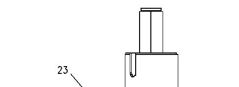
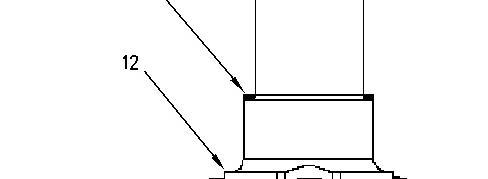

Illustration 8 g00906491
2. Place internal fillet spacer (23) onto main shaft (12).
Note: Not all assemblieswill require an internal fillet spacer. If necessary, the beveled edge must match the edge of the radiuson the main shaft. Refer to Illustration 9.
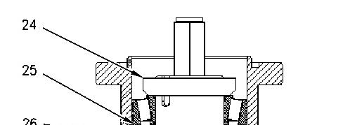
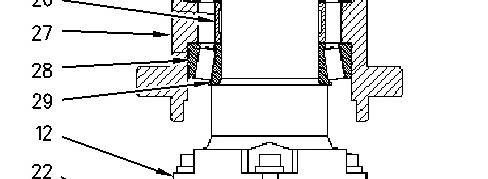

Illustration 9 g00906493
3. Push cups (28) into bearing carrier (27).
4. Slide first bearing cone (29) onto main shaft (12).
5. Slide bearing spacer (26) onto main shaft (12).
6. Slide shims (25) onto main shaft (12).
Note: Measure thicknessof the old shims and replace the old shimswith new shims which are supplied in a bearing kit.
7. Set bearing carrier (27) onto the first bearing set that is on the main shaft.
8. Place the second bearing cone into the bearing carrier.
9. Thread locknut (24) onto the main shaft and tighten the locknut with a certified torque wrench to the specific value.
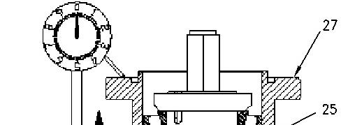
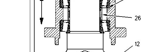
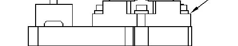
Illustration 10 g00906504
10. Mount a dial indicator that hasa magnetic base onto a stable base such as the fan mounting bracket.
11. Use the indicator to measure the vertical movement of bearing carrier (27) on the main shaft (12).
12. Raise and lower the bearing carrier to measure the vertical movement. Perform this step without any load.
Note: The vertical movement of the bearing carrier must be between the specified values. Refer to Table 1 for clearances.
Table 1
Bearing Clearances
(1) The shims come inthicknesses of 0.002, 0.003, 0.005, and0.010inches. The maximum stack height ofthe shims should not exceed 0.8890 mm (0.035 inch). The maximum numberof shims is 5.
13. Add and remove shims(25) to ensure that the vertical movement iswithin the specifications.
14. Remove the dial indicator from the assembly.
15. Remove locknut (24) from main shaft (12).
Note: While you remove the components, stack the components in the same order. This will ease assembly later.
16. Lift off bearing carrier (27) and place the bearing carrier to the side. Place the top bearing on top of the locknut.
17. Remove shims(25), bearing spacer (26), and the lower bearing cone from main shaft (12).
Bearing Carrier - Assemble
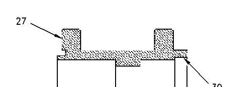
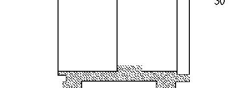

Illustration 11 g00906544
1. Clean the seal bore (30) of bearing carrier (27) with 138-8441 Brake Cleaner to remove any adhesives or debris.
2. Place bearing carrier (27) horizontally.
3. Apply 4C-9507 Retaining Compound and 169-5464 Quick Cure Primer to seal bore (30) of bearing carrier (27). Also, apply thisadhesive to the bore surface of the seal. Coat the surfaces completely.
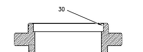
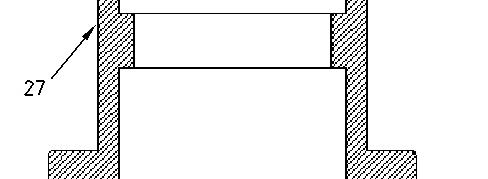

Illustration 12 g00906549
4. Place bearing carrier (27) vertically so that the seal bore (30) is directed upward.
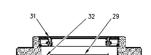
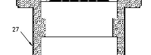

Illustration 13 g00906552
5. Place first main bearing cone (29) into the cup (32) of bearing carrier (27).
6. Press seal (31) into the seal bore until the face of the seal is flush with the edge of bearing carrier (27).
Note: The seal must be square with the seal bore of the bearing carrier to ensure the proper seal.
7. Flip bearing carrier (27) so that the seal bore isfacing downward on the work surface.
Note: If the fan assembly contains a spool, proceed to "Main Shaft and Bearing Carrier Assembly for Fans with Spools". If the fan assembly does not contain a spool proceed directly to "Main Shaft and Bearing Carrier Assembly for Fanswithout Spools".
Main Shaft and Bearing Carrier Assembly for Fanswith Spools
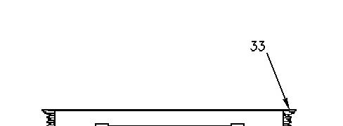
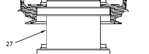

Illustration 14 g00906559
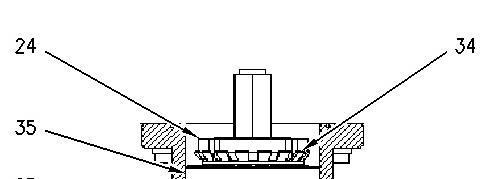
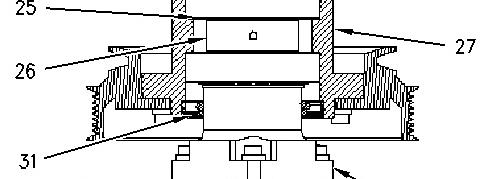
Illustration 15 g00906562
1. Install pulley (33) onto bearing carrier (27).
2. Lubricate seal (31) with light oil.
3. Install bearing carrier assembly (27) onto main shaft (12).
Note: When you slide seal (31) over the shoulder of main shaft (12), take care not to damage the seal. Also, make sure that no part of the lip of the seal is turned upward.
4. Install the spacer for the bearing carrier (27) and shims (25) onto main shaft (12).
Note: When you install shims, place the smaller thicknessesfirst. Turn burrs upward on the main shaft.
5. Slide second bearing set (35) and lockwasher (34) onto main shaft (12).
6. Apply 4C-9506 Retaining Compound to the threads on the main shaft. Thread locknut (24) onto main shaft (12). Tighten the locknut to the correct specification.
Note: The beveled edge of the locknut must face toward the lockwasher. Align one of the slots on the locknut with one of the tabs on the lockwasher. When you align the tab and the slot, always tighten the locknut. Never loosen the locknut when you are aligning the tab and the slot.
This is the sample of the manual
Click on the download link for complete Manual
7. Bend the lockwasher tab onto the slot of the locknut.


8. Clean the O-ring groove and install O-ring (35) on the carrier.
Note: Apply Steps9 through 16 only if the flange and/or the oil dam were removed from the spool.