

Product: MOTOR GRADER
Model: 14G MOTOR GRADER 96U
Configuration: 14G MOTOR GRADER 96U00001-01097 (MACHINE)
Disassembly and Assembly SINGLE CYLINDER AIR COMPRESSOR
REG013430006
Air Governor
SMCS - 1065-15; 1065-16
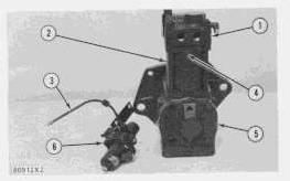
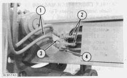
Disassemble Air Governor
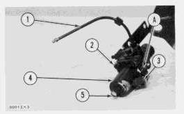
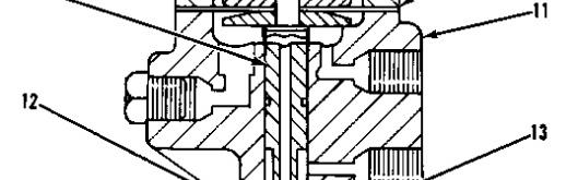
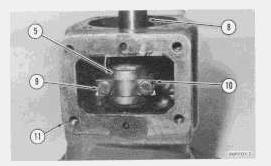
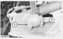
1. Remove air governor from air compressor. Remove air line (1) from body (11).
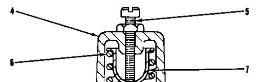
2. Put a mark (A) on cover (4) and body (11) so the cover can be installed on the body in the correct location.
3. Measure the distance from cover (4) to the top of screw (5) and make a record of the measurement. Loosen the locknut and remove screw (5).
4. Remove four screws (2), identification tag (3), cover (4), spring (6) and spring seat (7).
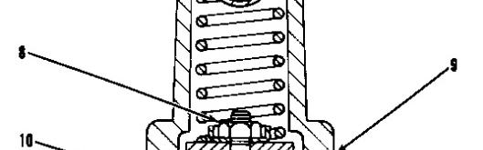
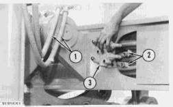
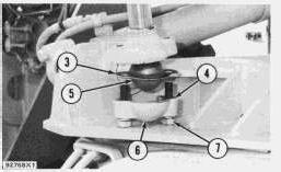
5. Remove nut (8), plunger (10) and diaphragm (9) as a unit.
This is the sample of the manual
Click on the download link for complete Manual
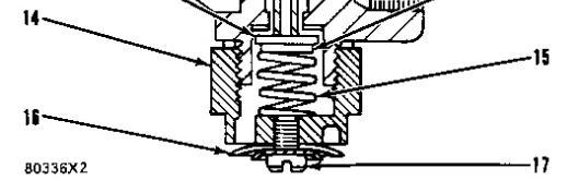
6. A rod with a diameter of .12 in. (3.05 mm) put in the hole in plunger (10) is used to hold the plunger when nut (8) is removed.
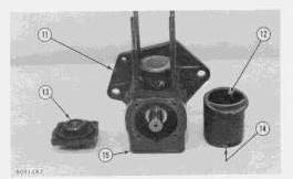
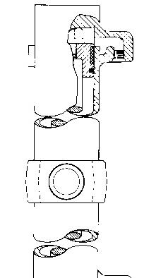
7. Remove screw (17) and exhaust diaphragm (16).
8. Remove exhaust nut (14), spring (15), exhaust valve (12) and spring retainer (13).
9. Clean all of the parts and the passages in body (11) and plunger (10).
Assemble Air Governor

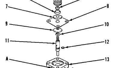
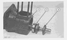
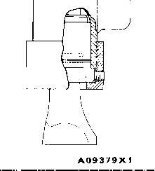
1. Install seal (12) on plunger (11).
2. Put new soft washer (10), follower (9), new diaphragm (8), follower (7), spring guide (5) and new nut (6) on plunger (11).
NOTE: The diaphragm is between the chamfered sides of followers (7) and (9).
3. A rod with a diameter of .12 in. (3.05 mm) put in the hole in plunger (11) is used to hold the plunger when nut (6) is tightened.
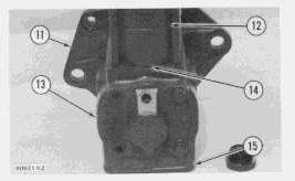
4. Lubricant is put on plunger (11) and in body (13). Install plunger in body.
5. Install spring seat (3) in spring (4) and put them on spring guide (5).
6. Install cover (2) over spring seat (3) and spring (4). Mark (A) on cover (2) must be in alignment with mark (A) on body (11) when the four lockwashers and screws in the cover are tightened.
NOTE: The governor identification tag is under one of the four screws.
7. Install screw and nut (1) in cover (2). Make an adjustment for the length of the screw to get the same measurement before the screw was removed from the cover.
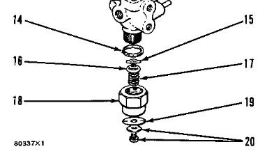
8. Install screw and diaphragm washer (20) and new exhaust diaphragm (19) on exhaust nut (18).
9. Install spring (17), spring retainer (16) and new exhaust valve (15) in exhaust nut (18).
10. Install washer (14) and exhaust nut (18), spring retainer and spring in body (13). Install air governor and air line on air compressor.
1993 - 2024 Caterpillar Inc.
Product: MOTOR GRADER
Model: 14G MOTOR GRADER 96U
Configuration: 14G MOTOR GRADER 96U00001-01097 (MACHINE)
Disassembly and Assembly
SINGLE CYLINDER AIR COMPRESSOR
REG013430005
Crankshaft
SMCS - 1065-11; 1065-12
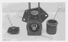
Remove Crankshaft
start by:
a) remove head assembly
b) remove piston and rod
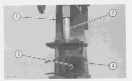
1. A press (1) can be used to remove crankshaft (3) from crankcase (4).

2. Put a pipe (2), with a bore larger than 1.03 in. (26.2 mm) and a diameter of approximately 2 in. (50.8 mm) with an approximate length of 6 in. (152.4 mm), over the end of crankshaft (3) and on bearing (5).
3. Push crankshaft (3) and bearing (5) out of crankcase (4) as a unit.
4. Remove bearing (5).
Install Crankshaft
1. Heat the crankshaft ball bearing in oil to a temperature of not over 350°F (175°C) and put the bearing on crankshaft (3).
2. Put the bearing and crankshaft (3) into crankcase (1) with the crankcase resting on the large flange end.
3. Outer race (2) of the bearing is pushed into the crankcase with a soft metal rod put at many locations on outer race (2) while hitting the rod with a hammer.
end by:
a) installing piston and rod
b) installing head assembly
Product: MOTOR GRADER
Model: 14G MOTOR GRADER 96U
Configuration: 14G MOTOR GRADER 96U00001-01097 (MACHINE)
Disassembly and Assembly
SINGLE CYLINDER AIR COMPRESSOR
Head Assembly
SMCS - 1065-11; 1065-12; 1065-17
Remove Head Assembly
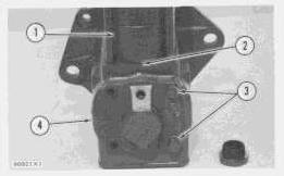
1. Loosen two set screws (1) and cover (2).
REG013430003
2. Put alignment marks on head assembly (3) and on cylinder (5) and also on the cylinder and on crankcase (7) so parts can be put in correct location when they are assembled.
3. Disconnect air line (4) and remove two bolts (8) and governor assembly (6).
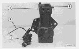
4. Remove four nuts (9) and remove head assembly (3).
NOTE: If needed, hit head assembly (3) with a soft hammer and then remove the head assembly.
Install Head Assembly
1. Install new gasket (4) on cylinder (2).
2. Install head assembly (1) on cylinder (2).
3. Put alignment marks on the cylinder and head assembly together and tighten four nuts (8). Torque for nuts is 14 ± 3 lb.ft. (1.9 ± 0.4 mkg).
4. Install governor assembly (6) on end cover (5) and tighten bolts (10). Torque for bolts is 10 lb.ft. (1.38 mkg). Connect air line (3) to head assembly (1).
5. Tighten cover (7). Torque for cover is 60 lb.ft. (8.3 mkg).
6. Tighten two set screws (9). Torque for set screws is 50 to 96 lb.in. (57.6 to 110.7 cm.kg).
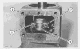
Disassemble And Assemble
start by:
a) remove head assembly
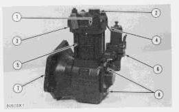
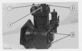
1. Remove cover (7), unloader valve (1) and spring (2) from top half (3) of head and clean the unloader valve.
2. Remove two set screws from top half (3) and hit either top half (3) or bottom half (4) with a soft hammer to separate the head.
3. Remove and clean exhaust valve (5) and spring (6).
4. Remove and clean inlet valve (8) and spring.
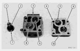
5. Clean all of the passages in both top half (3) and bottom half (4).
6. Place a new gasket (10), spring (6) and exhaust valve (5) on bottom half (4) of the head.
7. Place inlet valve (8) and spring (9) on top half (3) of the head.
8. Carefully put half (3) on half (4). Inlet valve (8) can be moved to the correct location with a rod through the opening for the unloader valve.
9. Install the two set screws to hold the top half (3) and the bottom half (4) of the head together.
10. Install unloader valve (1), spring (2) and cover (7) in the head.
end by:
a) install head assembly Copyright 1993 - 2024 Caterpillar Inc.
Network For SIS Licensees. Sun Sep 15 00:39:31 UTC+0530 2024
Product: MOTOR GRADER
Model: 14G MOTOR GRADER 96U
Configuration: 14G MOTOR GRADER 96U00001-01097 (MACHINE)
Disassembly and Assembly
SINGLE CYLINDER AIR COMPRESSOR
REG013430004
Piston
And Rod
SMCS - 1065-11; 1065-12
Piston And Rod Removal
start by:
a) remove head assembly
1. Remove cylinder (1) and gasket (2).
2. Remove bolts (3) and end cover (4).
3. Remove four bolts and cover (6).
4. Put marks on rod cap (9) and rod (10) so rod and rod cap can be installed on crankshaft (11) in the same location as they were removed.
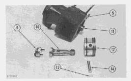
5. Bend lock (7) and remove bolts (8) and rod cap (9). Remove rod (10) and piston (12) from crankcase (5).
6. Mark piston (12) so it can be installed on rod (10) in the same location as it was removed.
7. Remove pin lock (13) and push pin (4) out of piston (12) and rod (10).
8. Clean all parts.
9. Remove piston rings and clean the ring grooves in piston (12) with a piece of hard wood.
Install Piston And Rod
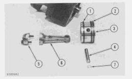
1. The gap for oil ring (1) and the gap for rings (2) is measured with the rings near the bottom in cylinder (12). The gap for each ring is .003 to .009 in. (0.08 to 0.23 mm).
2. Install rings (1) and (2) on piston (3). The gap for each ring must not be near the piston pin bore and each gap must be approximately 120° from the gap in the next ring.
3. Install pin (4) in piston (3) and rod (6). Install pin lock (7). The mark put on the piston shows if the location of the piston on the rod is correct.
4. Put rod (6) and piston (3) into crankcase (11). Install rod cap (5). The marks put on the rod cap and rod show the correct location of the rod in crankcase (11).
5. Tighten bolts (9) to a torque of 35 to 40 lb.in. (40.6 to 46.1 cm.kg). Bend lock (10) over bolt heads.
6. Put a new gasket on both end cover (13) and cover (15) and install the covers and gaskets on crankcase (11).
7. Put a new gasket (14) on cylinder (12) and put the gasket and cylinder on crankcase (11). The marks put on the cylinder and crankcase, before the head assembly was removed, must be together.
a) install head assembly Copyright 1993 - 2024 Caterpillar Inc.
Rights Reserved.
Network For SIS Licensees. Sun Sep 15 00:39:46 UTC+0530 2024
Product: MOTOR GRADER
Model: 14G MOTOR GRADER 96U
Configuration: 14G MOTOR GRADER 96U00001-01097 (MACHINE)
Disassembly and Assembly
14G MOTOR GRADER VEHICLE SYSTEMS
Air Tank
SMCS - 4272-11; 4272-12
Remove Air Tank
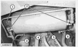
1. Release the air pressure in the air tank by loosening bleed valves (2).
Do not disconnect any air lines from the air tank until air pressure is zero.
2. Disconnect air lines (3), (4) and (6) from the air tank.
3. Remove nuts (1), the washers, and the bolts from each end of the tank. Remove air tank (5).
Install Air Tank
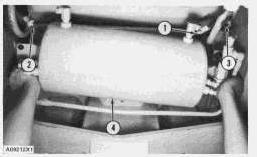
1. Put air tank (4) in position on the frame. Install the bolts, washers and the nuts that hold it.
2. Connect air lines (1), (2) and (3) to their correct locations on the air tank.
Copyright 1993 - 2024 Caterpillar Inc. All Rights Reserved. Private Network For SIS Licensees.
Sun Sep 15 01:03:48 UTC+0530 2024
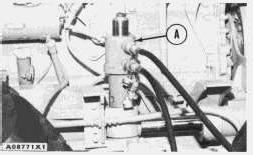
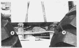
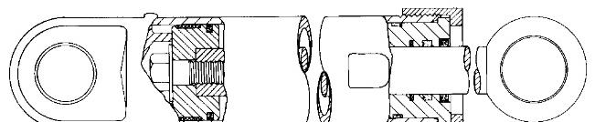
3. Remove pins (2) from each end of the cylinder with tooling (A).
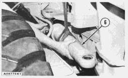
4. Fasten a hoist to the cylinder. Remove articulation cylinder (6) and the washers from the machine. Weight is 76 lb. (34 kg).
5. Repeat Steps 1 through 4 for the other articulation cylinder.
NOTE: See DISASSEMBLE AND ASSEMBLE HYDRAULIC CYLINDERS.
Install Articulation Cylinders
1. Fasten a hoist to articulation cylinder (1) and put it in position on the machine.
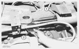
2. Put washers (2) in position on top of the rod end of the cylinder.
3. Install the pin in each end of the cylinder. Install the bolt and washer that hold each pin to the frame.
4. Connect the oil lines to their correct locations on the cylinder.
5. Fasten a hoist to battery box (4). Put the battery box in position on the brackets. Install the washers and bolts (3) that hold the battery box to the brackets.
6. Connect the battery cables to the battery.
7. Repeat Steps 1 through 6 for the other articulation cylinder.
Product: MOTOR GRADER
Model: 14G MOTOR GRADER 96U
Configuration: 14G MOTOR GRADER 96U00001-01097 (MACHINE)
Disassembly and Assembly 14G MOTOR GRADER VEHICLE SYSTEMS
Articulation Lock Check Valve, Blade Lift Lock Check Valve
SMCS - 5235-11; 5235-12
Remove Articulation Lock Check Valve
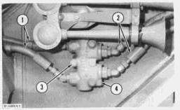
1. Put identification on all oil lines as to their location on the lock check valve. Disconnect oil lines (1) and (2) from the lock check valve.
2. Remove bolts (3) that hold lock check valve to the frame. Remove articulation lock check valve (4).
Install Articulation Lock Check Valve
1. Put articulation lock check valve (1) in position on the frame. Install the bolts that hold it.
2. Connect oil lines (2) and (3) to their correct locations on the valve.
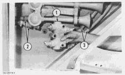
Remove Blade Lift Lock Check Valve
1. Lower the blade to the ground.
2. Put identification on oil lines as to their correct location on the lock check valve. Disconnect oil lines (1) and (2) from the lock check valve.
3. Remove bolts (3) that hold lock check valve to the frame. Remove blade lift lock check valve (4).
Install Blade Lift Lock Check Valve
1. Put blade lift lock check valve (3) in position on the frame. Install the bolts that hold it.
2. Connect oil lines (1) and (2) to their correct location on the valve.
Copyright 1993 - 2024 Caterpillar Inc. All Rights Reserved. Private Network For SIS Licensees. Sun Sep 15 00:45:35 UTC+0530 2024
Product: MOTOR GRADER
Model: 14G MOTOR GRADER 96U
Configuration: 14G MOTOR GRADER 96U00001-01097 (MACHINE)
Disassembly and Assembly
14G MOTOR GRADER VEHICLE SYSTEMS
Media Number -REG01699-02
Publication Date -01/08/1980
Ball And Socket Joint Inserts (Earlier)
SMCS - 5102-11; 5102-12
Date Updated -10/10/2001
Remove And Install Ball And Socket Joint Inserts (Earlier)
This is the sample of the manual
Click on the download link for complete Manual
1. Remove bolts (2) and cap (1) from the blade lift cylinders or the blade centershift cylinder. Remove the insert from the cap. Start the engine. Move the cylinder rod free of the ballstud. Remove the insert from the ballstud. Shut off the engine.
2. Put 5P960 Grease on the inside surfaces of the inserts.
3. Install new insert (3) on ballstud (5). Start the engine. Move the cylinder rod in position on the ballstud. Install new insert (4) in cap (6). Put cap (6) in position on the ballstud. Install bolts (7) that hold it to the cylinder.
Copyright 1993 - 2024 Caterpillar Inc. All Rights Reserved. Private Network For SIS Licensees.
Sun Sep 15 00:53:17 UTC+0530 2024