

Product: MOTOR GRADER
Model: 143H MOTOR GRADER APN
Configuration: 143H Motor Grader APN00001-UP (MACHINE) POWERED BY 3176C Engine
Disassembly and Assembly
143H and 163H Motor Graders 3176C Engine Supplement
Aftercooler - Remove and Install
SMCS - 1063-010
S/N - APN1-UP
Removal Procedure
Start By:
A. Remove the radiator guard and support. Refer to Disassembly and Assembly, "Radiator Guard and Support, Aftercooler, and Radiator - Remove".
B. Remove the hydraulic oil cooler. Refer to Disassembly and Assembly, "Hydraulic Oil CoolerRemove and Install".
Note: Cleanliness is an important factor. Before the disassembly procedure, the exterior of the component should be thoroughly cleaned. This will help to prevent dirt from entering the internal mechanism.
Note: Put identification marks on all lines, on all hoses, on all wires, and on all tubes for installation purposes. Plug all lines, hoses, and tubes. This helps to prevent fluid loss and this helps to keep contaminants from entering the system.
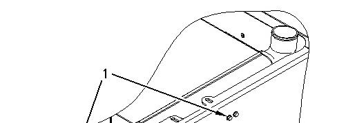
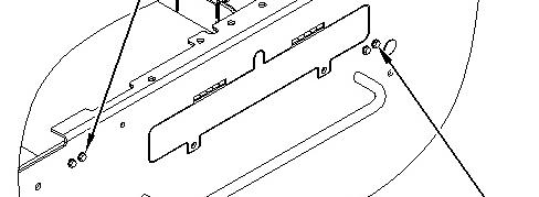
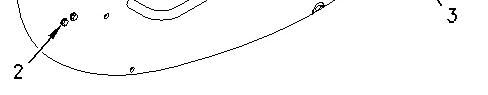
Illustration 1 g00991128
1. Remove bolts (1), (2), and (3). Repeat this step for the opposite side.
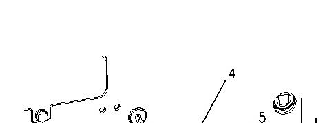
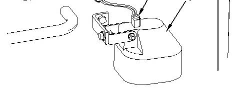

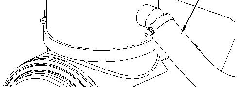
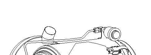
Illustration 2 g00919910
2. Disconnect harness assembly (4) from light (5). Repeat this step for the opposite side.
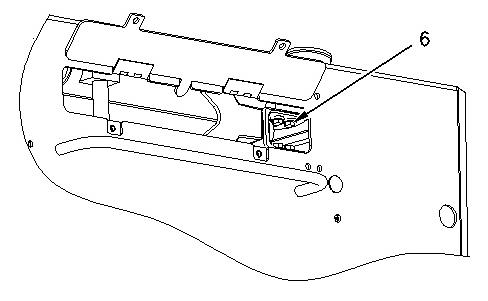
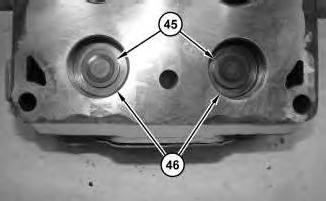
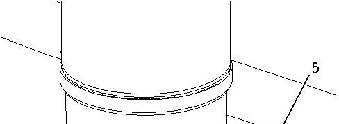
Illustration 3 g00991135
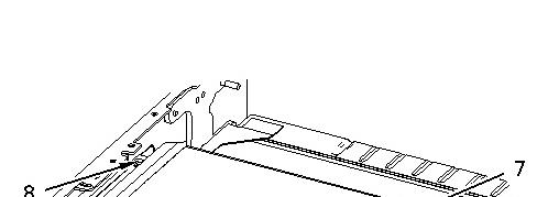
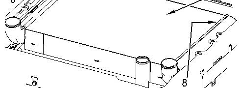

Illustration 4 g00991137
3. Position the aftercooler and the radiator in order to remove bolts (6) .
4. Remove bolts (6) from aftercooler (7) .
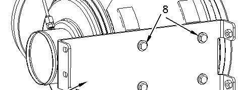
5. Remove bolts (8) and the spacers.
6. Use two people to remove aftercooler (7) .
Note: Do not damage the radiator.
Installation Procedure

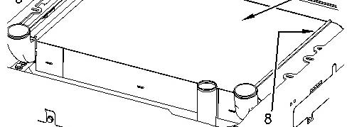

Illustration 5 g00991137
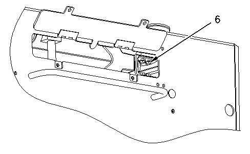
Illustration 6 g00991135
1. Use two people to install aftercooler (7) .
Note: Do not damage the radiator.
2. Install bolts (8) and the spacers.
3. Install bolts (6) on aftercooler (7) .
4. Carefully position the aftercooler and the radiator in order to install bolts (6) .
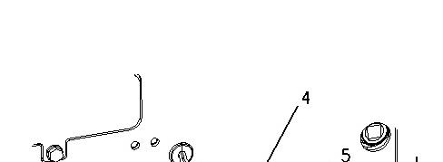
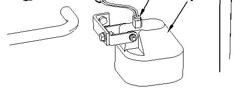
Illustration 7 g00919910
5. Connect harness assembly (4) on light (5). Repeat this step for the opposite side.
Illustration 8 g00991128
6. Install bolts (1), (2), and (3). Repeat this step for the opposite side.
End By:
a. Install the hydraulic oil cooler. Refer to Disassembly and Assembly, "Hydraulic Oil CoolerRemove and Install".
b. Install the radiator guard and support. Refer to Disassembly and Assembly, "Radiator Guard and Support, Aftercooler, and Radiator - Install". Copyright 1993 - 2023 Caterpillar Inc.
Product: MOTOR GRADER
Model: 143H MOTOR GRADER APN
Configuration: 143H Motor Grader APN00001-UP (MACHINE) POWERED BY 3176C Engine
Disassembly and Assembly
143H and 163H Motor Graders 3176C Engine Supplement
Air Cleaner - Remove and Install
SMCS - 1051-010-HG; 1054-010
S/N - APN1-UP
Removal Procedure
Start By:
A. Remove the hood. Refer to Disassembly and Assembly, "Hood - Remove and Install".
i01794384
This is the sample of the manual
Click on the download link for complete Manual
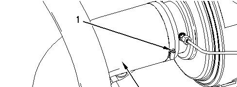
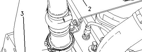
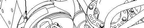
Illustration 1 g00918404
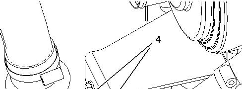
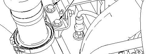
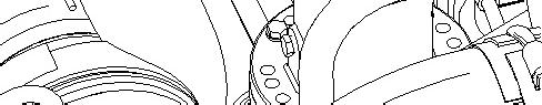
Illustration 2 g00918406

3 g00918407
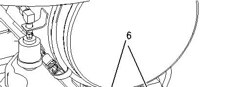
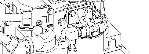
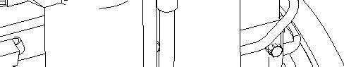
Illustration 4 g00918409
.
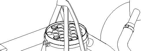
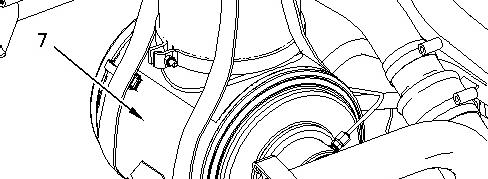

Illustration 5 g00918411
5. Attach a suitable lifting device to air cleaner (7). Remove air cleaner (7). The weight of air cleaner (7) is approximately 27 kg (60 lb).
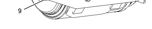
6 g00918414
6. Remove bolts (8) and remove plate (9) .
Installation Procedure
7 g00918414
Illustration 8 g00918411
2. Attach a suitable lifting device to air cleaner (7). Install air cleaner (7). The weight of air cleaner (7) is approximately 27 kg (60 lb).
Illustration 9 g00918409
10 g00918407
11 g00918406
Illustration 12 g00918404
6. Position hose (2) to the original location and tighten clamp (3). Connect hose (2) and tighten clamp (1) .
End By: Install the hood. Refer to Disassembly and Assembly, "Hood - Remove and Install". Copyright 1993 - 2023 Caterpillar Inc. All Rights Reserved. Private Network For SIS Licensees. Sun Oct 1 14:06:25 UTC+0530 2023
Product: MOTOR GRADER
Model: 143H MOTOR GRADER APN
Configuration: 143H Motor Grader APN00001-UP (MACHINE) POWERED BY 3176C Engine
Disassembly and Assembly
143H and 163H Motor Graders 3176C Engine Supplement
Air Compressor - Assemble
SMCS - 1803-016
Assembly Procedure Table 1
i04828134
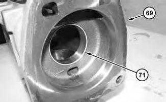
1. Install bearing (71) into compressor housing (69).
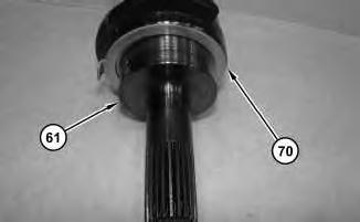
Illustration 2
2. Install thrust washer (70) onto crankshaft (61).
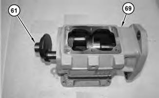
Illustration 3
3. Install crankshaft (61) into compressor housing (69).
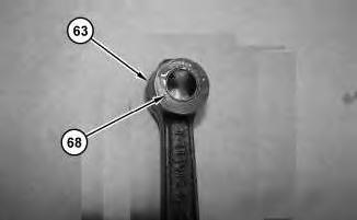
Illustration 4
g02961381
4. Install bearing (68) into connecting rod (63). Repeat this step for the remaining connecting rod assembly
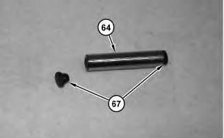
Illustration 5
5. Install caps (67) onto wrist pin (64).
g02961378
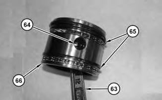
Illustration 6
g02961357
6. Install piston rings (65). Install piston (66) onto connecting rod (63). Install wrist pin (64). Repeat this step for the remaining piston and connecting rod assembly.
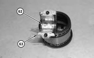
Illustration 7
7. Install bearing (62) onto connecting rod (63). Repeat this step for the remaining connecting rod.
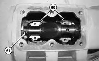
Illustration 8
g02961326
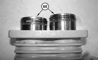
Illustration 9
g02961337
8. Install piston and connecting rod assemblies (60). Push piston and connecting rod assemblies (60) into the block and onto crankshaft (61).
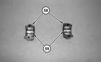
Illustration 10
9. Install bearings (59) onto bearing caps (58).
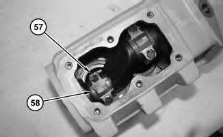
Illustration 11
g02961316
10. Install bearing cap (58). Install bolts (57). Repeat this step for the remaining bearing cap.
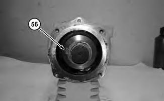
Illustration 12
11. Install thrust washer (56).
13
14
g02961216
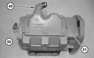
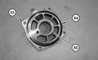
Illustration 15
g02961198
This is the sample of the manual
Click on the download link for complete Manual
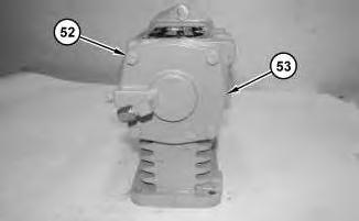
14. Install cover (51). Install bolts (50). Install fitting (49).
16
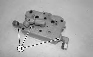
15. Install fittings (48).
17
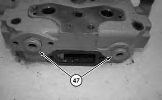
16. Apply Tooling (B) onto plugs (47). Install plugs (47).