

Product: MOTOR GRADER
Model: 140M MOTOR GRADER D9G
Configuration: 140M Motor Grader - All Wheel Drive D9G00001-UP (MACHINE) POWERED BY C9 Engine
Disassembly and Assembly
140M Motor Grader Engine Supplement
Media Number -KENR6423-02
Aftercooler - Install
SMCS - 1063-012
Installation Procedure Table 1
Required Tools
140-7742 Sleeve 1
B 138-7573 Link Bracket 1
Note: Cleanliness is an important factor. Before you begin the installation procedure, the exterior of the components should be thoroughly cleaned. This will help to prevent dirt from entering the internal mechanism.
Note: Check the O-ring seals, the gaskets, and the seals for wear or for damage. Replace the components, if necessary.
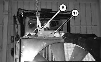
Illustration 1
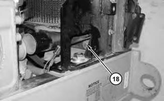
Illustration 2
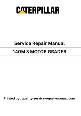
1. Attach Tooling (B) and a suitable lifting device to aftercooler (17). Install aftercooler (17). The weight of aftercooler (17) is approximately 18 kg (40 lb). Install bolts (18) .
Illustration 3
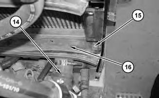
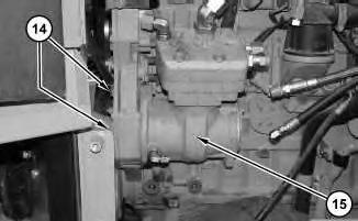
2. Install hose (14). Tighten the clamp on hose (14) to a torque of 12 ± 1 N·m (106 ± 9 lb in). Install bolt (15) .
3. Repeat Step 2 for the other side. Install plate (16) .

4
4. Position core assembly (10). Install bolts (11). Install bolt (12) .
5. Repeat Step 4 for the other side. Install plate (13) .
5
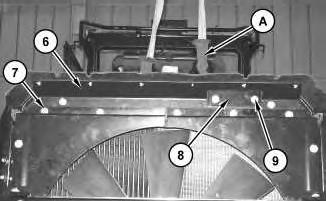
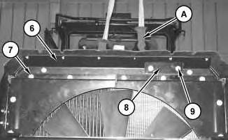
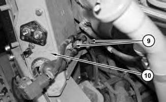
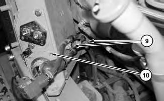
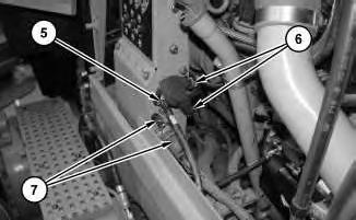
6. Use a suitable lifting device and Tooling (A) in order to support bracket assembly (6). Install bracket (8). Install bracket assembly (6) and bolts (7). Install bolts (9) .
6
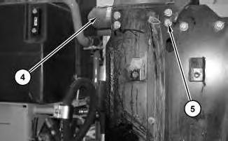
7. Install hose (4). Tighten the clamp on hose (4) to a torque of 12 ± 1 N·m (106 ± 9 lb in). Install bolts (5) .
8. Repeat Step 7 for the other side.
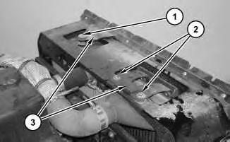
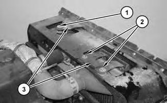
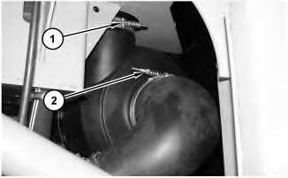
9. Position bracket assembly (3). Install bolt (1). Install bolts (2) .
End By:
a. Install the hydraulic oil cooler. Refer to Disassembly and Assembly, "Hydraulic Oil Cooler - Remove and Install".
b. Install the engine enclosure. Refer to Disassembly and Assembly, "Engine enclosureRemove and Install".
Jan 8 11:59:05 UTC+0530
Product: MOTOR GRADER
Model: 140M MOTOR GRADER D9G
Configuration: 140M Motor Grader - All Wheel Drive D9G00001-UP (MACHINE) POWERED BY C9 Engine
Disassembly and Assembly
140M Motor Grader Engine Supplement
Media Number -KENR6423-02
Aftercooler - Remove
SMCS - 1063-011
Removal Procedure Table 1
Required Tools
B 138-7573 Link Bracket 1
Start By:
A. Remove the engine enclosure. Refer to Disassembly and Assembly, "Engine enclosureRemove and Install".
B. Remove the hydraulic oil cooler. Refer to Disassembly and Assembly, "Hydraulic Oil Cooler - Remove and Install".
NOTICE
Care must be taken to ensure that fluids are contained during performance of inspection, maintenance, testing, adjusting and repair of the product. Be prepared to collect the fluid with suitable containers before opening any compartment or disassembling any component containing fluids.
Refer to Special Publication, NENG2500, "Caterpillar Tools and Shop Products Guide" for tools and supplies suitable to collect and contain fluids on Caterpillar products.
Dispose of all fluids according to local regulations and mandates.
Note: Cleanliness is an important factor. Before you begin the removal procedure, the exterior of the components should be thoroughly cleaned. This will help to prevent dirt from entering the internal mechanism.
Note: Put identification marks on all hoses, on all hose assemblies, on all harness assemblies, and on all tube assemblies for installation purposes. Plug all hose assemblies and all tube assemblies. This helps to prevent fluid loss, and this helps to keep contaminants from entering the system.
2.
3. Repeat Step 2 for the other side.
3
4. Use a suitable lifting device and Tooling (A) in order to support bracket assembly (6). Remove bolts (9). Remove bracket (8). Remove bolts (7) and bracket assembly (6) .
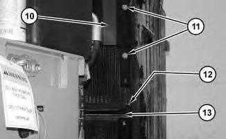
Illustration 4
g01410321
5. Remove bolts (11). Reposition core assembly (10). Remove bolt (12) .
6. Repeat Step 5 for the other side. Remove plate (13) .
5
7. Remove hose (14). Remove bolt (15) .
8. Repeat Step 7 for the other side. Remove plate (16) .

6
7
9. Attach Tooling (B) and a suitable lifting device to aftercooler (17). Remove bolts (18) and aftercooler (17). The weight of aftercooler (17) is approximately 18 kg (40 lb).
Copyright 1993 - 2020 Caterpillar Inc. All Rights Reserved. Private Network For SIS Licensees. Wed Jan 8 11:58:50 UTC+0530 2020
This is the sample of the manual
Click on the download link for complete Manual
Product: MOTOR GRADER
Model: 140M MOTOR GRADER D9G
Configuration: 140M Motor Grader - All Wheel Drive D9G00001-UP (MACHINE) POWERED BY C9 Engine
Disassembly and Assembly
140M Motor Grader Engine Supplement
Media Number -KENR6423-02
Publication Date -01/06/2009
Air Cleaner - Remove and Install
SMCS - 1051-010-HG; 1054-010
Removal Procedure
Date Updated -26/06/2009
2
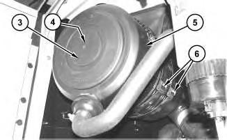
2. Remove cover (3) and remove element (4) (not shown).
3. Disconnect clamps (6) and remove air cleaner housing (5) .
Installation Procedure
Illustration 3
1. Position air cleaner housing (5) and connect clamps (6) .
2. Install element (4) (not shown) and install cover (3) .
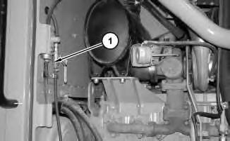
3. Position clamp (2) and tighten clamp (2) to a torque of 6 ± 1 N·m (53 ± 9 lb in).
4. Position clamp (1) and tighten clamp (1) to a torque of 5 N·m (44 lb in).
Copyright 1993 - 2020 Caterpillar Inc. All Rights Reserved. Private Network For SIS Licensees. Wed Jan 8 11:51:56 UTC+0530 2020
Product: MOTOR GRADER
Model: 140M MOTOR GRADER D9G
Configuration: 140M Motor Grader - All Wheel Drive D9G00001-UP (MACHINE) POWERED BY C9 Engine
Disassembly and Assembly
140M Motor Grader Engine Supplement
Media Number -KENR6423-02
Air Compressor - Remove and Install
SMCS - 1803-010
Removal Procedure
NOTICE
Keep all parts clean from contaminants.
Contaminants may cause rapid wear and shortened component life.
NOTICE
Care must be taken to ensure that fluids are contained during performance of inspection, maintenance, testing, adjusting and repair of the product. Be prepared to collect the fluid with suitable containers before opening any compartment or disassembling any component containing fluids.
Refer to Special Publication, NENG2500, "Caterpillar Tools and Shop Products Guide" for tools and supplies suitable to collect and contain fluids on Caterpillar products.
Dispose of all fluids according to local regulations and mandates.
Do not disconnect the air lines until the air pressure in the system is at zero. If hose is disconnected under pressure it can cause personal injury.
Note: Put identification marks on all hoses, on all hose assemblies, on all harness assemblies, and on all tube assemblies for installation purposes. Plug all hose assemblies and all tube assemblies. This helps to prevent fluid loss, and this helps to keep contaminants from entering the system.
1. Drain the coolant from the cooling system into a suitable container for proper storage or for disposal. Refer to Operation and Maintenance Manual, "Capacities - Refill" for the capacity of the cooling system. Refer to Operation and Maintenance Manual, "Cooling System
Coolant (DEAC) - Change" or Operation and Maintenance Manual, "Cooling System
Extended Life Coolant - Change" for the proper draining procedure.
2. Move the battery disconnect switch to the OFF position.
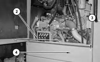
4. Disconnect rod (2). Remove bolts (3). Remove panel (4) .

Illustration 3
5. Disconnect harness assembly (5). Disconnect harness assemblies (6). Disconnect harness assemblies (7) .
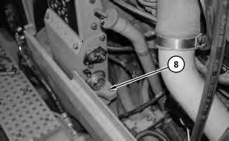
Illustration 4
6. Remove bolts (8) .
5
7. Remove bolts (9). Remove circuit breaker panel (10) .
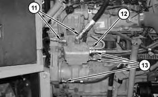
Illustration 6
8. Disconnect hose assemblies (11). Disconnect tube assembly (12). Disconnect hose assemblies (13) .
7
9. Remove bolts (14). Remove air compressor (15) .
Installation Procedure
Table 1
Required Tools
A 5P-3413 Pipe Sealant 1
Illustration 8
g01411248
1. Position air compressor (15). Install bolts (14) in order to secure air compressor (15) .
Illustration 9
g01411238
2. Apply Tooling (A) to the treads of hose assemblies (13). Connect hose assemblies (13). Apply Tooling (A) to the treads of tube assembly (12). Connect tube assembly (13). Apply Tooling (A) to the treads of hose assembly (11). Connect hose assembly (11) .
10
12
5. Connect harness assemblies (7). Connect harness assemblies (6). Tighten the nut for harness assemblies (6) to a torque of 30 ± 7 N·m (22 ± 5 lb ft). Connect harness assemblies (5). Tighten the nut for harness assembly (5) to a torque of 50 ± 10 N·m (36 ± 7 lb ft).
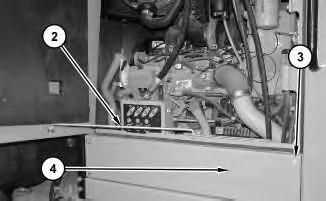
Illustration 13
6. Install panel (4). Install bolts (3). Connect rod (2) .
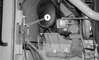
Illustration 14
g01411076
7. Move ball valve (1) to the CLOSED position.
8. Move the battery disconnect switch to the ON position.
9. Fill the cooling system with coolant. Refer to Operation and Maintenance Manual, "Capacities - Refill" for the capacity of the cooling system. Refer to Operation and Maintenance Manual, "Cooling System Coolant (DEAC) - Change" or Operation and Maintenance Manual, "Cooling System Extended Life Coolant - Change" for the proper draining procedure.
Product: MOTOR GRADER
Model: 140M MOTOR GRADER D9G
Configuration: 140M Motor Grader - All Wheel Drive D9G00001-UP (MACHINE) POWERED BY C9 Engine
Disassembly and Assembly
140M Motor Grader Engine Supplement
Media Number -KENR6423-02
Alternator - Remove and Install
SMCS - 1405-010
Removal Procedure
Personal injury can result from failure to disconnect the battery.
First, disconnect the negative battery cable. Then, disconnect the positive battery cable.
A positive power lead can cause sparks if the battery is not disconnected. Sparks can possibly result in battery explosion or fire.
1. Connect the steering frame lock. Refer to Operation and Maintenance Manual, "Steering Frame Lock".
2. Turn the key for the battery disconnect switch to the OFF position. Remove the key.
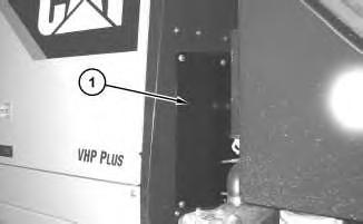
Illustration 1
3. Remove cover (1) .
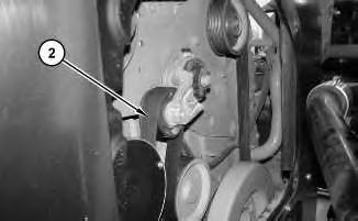
Illustration 2
g01405776
4. Remove belt (2). Refer to Operation and Maintenance Manual, "Belt - Replace".
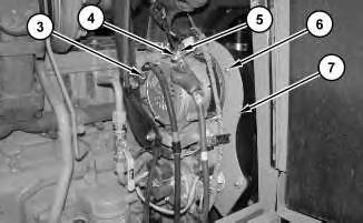
Illustration 3
g01405779
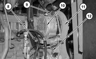
5. Disconnect cable assembly (3) and (5). Disconnect harness assembly (4). Remove bolts (6) and cover (7) .
4
6. Remove bolts (9) and (12). Reposition bracket assembly (11). Remove bolt (8). Remove alternator (10) .
Installation Procedure
Personal injury can result from failure to disconnect the battery.
First, disconnect the negative battery cable. Then, disconnect the positive battery cable.
A positive power lead can cause sparks if the battery is not disconnected. Sparks can possibly result in battery explosion or fire.
Illustration 5 g01405811
1. Position alternator (10). Position bracket assembly (11). Install bolt (8) .
2. Install bolts (9) and (12) .

Illustration 6
g01405779
3. Connect harness assembly (4). Connect cable assembly (5). Tighten the nut that secures cable assembly (5) to a torque of 18.2 ± 2.4 N·m (13 ± 2 lb ft). Connect cable assembly (3). Tighten the bolt that secures cable assembly (3) to a torque of 4.4 ± 1.0 N·m (39 ± 9 lb in).
4. Position cover (7) and install bolts (6) .
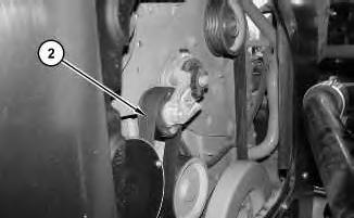
Illustration 7
g01405776
5. Install belt (2). Refer to Operation and Maintenance Manual, "Belt - Replace".
6. Install cover (1) .
7. Install the key. Turn the key for the battery disconnect switch to the ON position.
8. Disconnect the steering frame lock. Refer to Operation and Maintenance Manual, "Steering Frame Lock".
1993 - 2020 Caterpillar Inc.
Network For SIS Licensees. Wed Jan 8 11:54:19 UTC+0530 2020
Product: MOTOR GRADER
Model: 140M MOTOR GRADER D9G
Configuration: 140M Motor Grader - All Wheel Drive D9G00001-UP (MACHINE) POWERED BY C9 Engine
Disassembly and Assembly
140M Motor Grader Engine Supplement
Media Number -KENR6423-02
Battery - Remove and Install
SMCS - 1401-010
S/N - B9G1-UP
S/N - B9M1-UP
S/N - D9G1-UP
Removal Procedure
1. Turn the key for the battery disconnect switch to the OFF position. Remove the key.
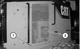
Illustration 1 g01373138
2. Remove bolts (1) and remove panel assembly (2) .
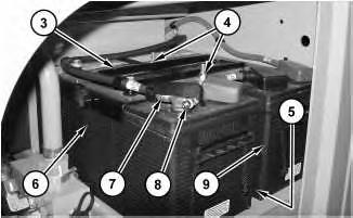
3. Loosen nut (8) and disconnect cable assembly (7) from the battery.
4. Remove nuts (4) and remove hold-down assembly (3)
5. Repeat Step 3 for the removal of the remaining cable assemblies.
6. Use two people in order to remove battery (6). The weight of battery (6) is approximately 45 kg (100 lb).
7. Remove bar (5) (not shown).
8. Use two people in order to remove battery (9)
Installation Procedure
This is the sample of the manual
Click on the download link for complete Manual
1. Use two people in order to position battery (9). The weight of battery (9) is approximately 45 kg (100 lb).
2. Install bar (5) (not shown).
3. Use two people in order to position battery (6) .
4. Position hold-down assembly (3) .
5. Apply Tooling (A) to nuts (4). Install nuts (4). Tighten nuts (4) to a torque of 12 ± 2 N·m (106 ± 18 lb in).
6. Connect cable assembly (7). Tighten nut (8) to a torque of 7.2 ± 1.6 N·m (63.7 ± 14.2 lb in).
7. Repeat Step 6 for the remaining cable assemblies.
Illustration 4
8. Position panel assembly (2) and install bolts (1) .
9. Install the key for the battery disconnect switch. Turn the battery disconnect switch to the ON position.
1993 - 2020 Caterpillar Inc.
SIS
Wed Jan 8 11:53:11 UTC+0530 2020