

Product: MOTOR GRADER
Model: 140K MOTOR GRADER SZL
Configuration: 140K Motor Grader SZL00001-UP (MACHINE) POWERED BY C7 Engine
Disassembly and Assembly
12K, 140K, 140K Series 2 and 160K Motor Graders Engine Supplement
Media Number -KENR8442-03
Publication Date -01/12/2010
Aftercooler - Remove and Install
SMCS - 1063-010
Removal Procedure
Date Updated -13/12/2010
i03425861
Note: Cleanliness is an important factor. Before the disassembly procedure, the exterior of the component should be thoroughly cleaned. This will help to prevent dirt from entering the internal mechanism.
Note: Put identification marks on all lines, on all hoses, on all wires, and on all tubes for installation purposes. Plug all lines, hoses, and tubes. This helps to prevent fluid loss and this helpsto keep contaminants from entering the system.
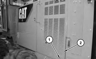
1. Remove bolts (1). Remove door (2) .
2
3
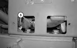
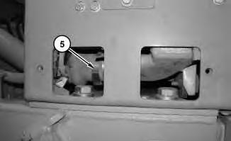
3. Remove clamp (5). Repeat for top clamp.
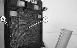
Illustration 4
g01778858
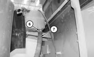
4. Remove bolts (6). Use two people in order to remove cover (7). The approximate weight of cover (7) is 27 kg (60 lb).
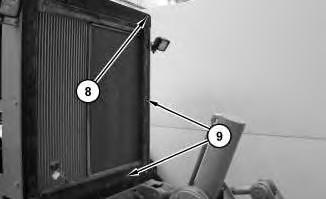
Illustration 5
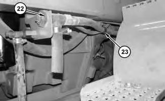
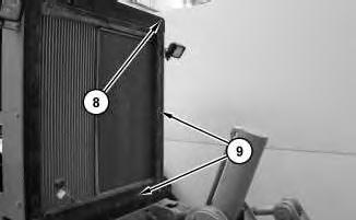
5. Remove bolts (8). Remove plates (9).
g01779598
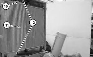
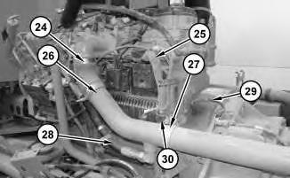
Illustration 6
g01793213
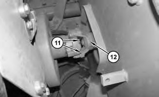
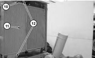
6. Remove bolts (12). Remove bracket (10). Use two people in order to remove aftercooler (11). The approximate weight of aftercooler (11) is 29 kg (65 lb).
Installation Procedure
7
1. Use two people in order to position aftercooler (11). The approximate weight of aftercooler (11) is 29 kg (65 lb). Position bracket (10). Install bolts (12) .
8
2. Position plates (9). Install bolts (8) .
9
3. Use two people in order to position cover (7). The approximate weight of cover (7) is 27 kg (60 lb). Install bolts (6) .
10
4. Install clamp (5). Repeat for top clamp.

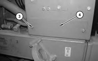
5. Position cover (4). Install bolts (3) .
12
6. Install door (2). Install bolts (1). Repeat steps for opposite side.
Copyright 1993 - 2020 Caterpillar Inc. All Rights Reserved. Private Network For SIS Licensees.
Product: MOTOR GRADER
Model: 140K MOTOR GRADER SZL
Configuration: 140K Motor Grader SZL00001-UP (MACHINE) POWERED BY C7 Engine
Disassembly and Assembly
12K, 140K, 140K Series 2 and 160K Motor Graders Engine Supplement
Media Number -KENR8442-03
Publication Date -01/12/2010
Air Cleaner - Remove and Install
SMCS - 1051-010-HG; 1054-010
Removal Procedure
Date Updated -13/12/2010
i03418160
Note: Cleanliness is an important factor. Before the disassembly procedure, the exterior of the component should be thoroughly cleaned. This will help to prevent dirt from entering the internal mechanism.
1
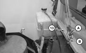
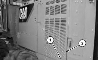
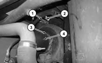
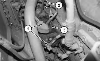
1. Remove clamps(1) and (3). Remove hoses(2) and (4).

2
2. Remove hose (7). Remove restriction indicator (5). Remove bolts (8). Remove air cleaner assembly (6) .
Installation Procedure
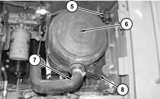
Illustration 3
g01782314
1. Position air cleaner assembly (6). Install bolts (8). Install restriction indicator (5). Install hose (7) .
This is the sample of the manual
Click on the download link for complete Manual
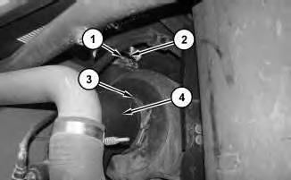
Illustration 4
2. Install hoses (2) and (4). Install clamps(1) and (3).
Copyright 1993 - 2020 Caterpillar Inc. All Rights Reserved. Private Network For SIS Licensees. Fri Oct 2 22:32:46 UTC+0530 2020
Product: MOTOR GRADER
Model: 140K MOTOR GRADER SZL
Configuration: 140K Motor Grader SZL00001-UP (MACHINE) POWERED BY C7 Engine
Disassembly and Assembly
12K, 140K, 140K Series 2 and 160K Motor Graders Engine Supplement
Media Number -KENR8442-03
Publication Date -01/12/2010
Air Compressor - Remove and Install
SMCS - 1803-010
Removal Procedure
Date Updated -13/12/2010
i03415965
Note: Cleanliness is an important factor. Before the disassembly procedure, the exterior of the component should be thoroughly cleaned. This will help to prevent dirt from entering the internal mechanism.
Note: Put identification marks on all lines, on all hoses, on all wires, and on all tubes for installation purposes. Plug all lines, hoses, and tubes. This helps to prevent fluid loss and this helpsto keep contaminants from entering the system.
NOTICE
Care must be taken to ensure that fluids are containedduring performance of inspection, maintenance, testing, adjusting and repair of the product. Be preparedto collect the fluid with suitable containers before opening any compartment or disassembling any component containing fluids.
Refer to Special Publication, NENG2500, "Caterpillar Dealer Service Tool Catalog" for toolsand supplies suitable to collect and contain fluids on Caterpillar products.
Dispose of all fluids according to local regulations and mandates.
1. Drain the cooling system. Refer to Operation and Maintenance Manual, "Cooling System CoolantChange" for the correct procedure.

Illustration 1
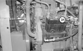
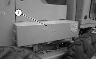
2. Remove mounting bolts (1) and remove side cover (2) .
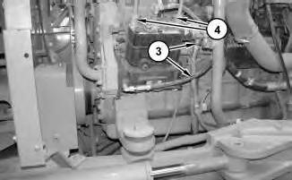
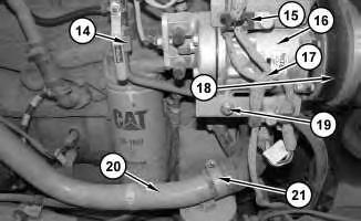
Illustration 2
g01774417
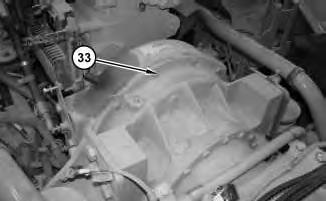
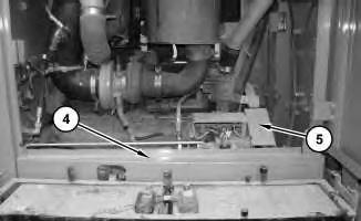
3. Remove hose assemblies(3). Disconnect tube assemblies (4) .
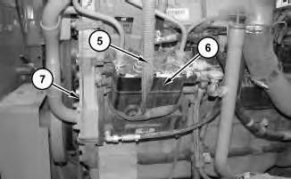
3
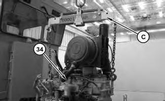
4. Use suitable lifting device (5). The approximate weight of the air compressor (6) is 27 kg (60 lb). Remove bolts (7).
Installation Procedure
Note: Cleanliness is an important factor. Before assembly, all partsshould be thoroughly cleaned in cleaning fluid. Allow the parts to air dry. Wiping cloths or rags should not be used to dry parts. Lint may be deposited on the partswhich may cause later trouble. Inspect all parts. If any parts are worn or damaged, use new parts for replacement.
Illustration 4
1. Attach a suitable lifting device (5). The approximate weight of air compressor (6) is 27 kg (60 lb). Install bolts (7) .
Illustration 5
2. Connect tube assemblies (4). Connect hose assemblies (3) .
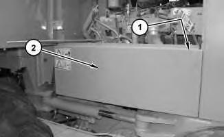
Illustration 6
3. Position side cover (2). Install bolts (1) .
Copyright 1993 - 2020 Caterpillar Inc. All Rights Reserved. Private Network For SIS Licensees. Fri Oct 2 22:33:53 UTC+0530 2020
Product: MOTOR GRADER
Model: 140K MOTOR GRADER SZL
Configuration: 140K Motor Grader SZL00001-UP (MACHINE) POWERED BY C7 Engine
Disassembly and Assembly
12K, 140K, 140K Series 2 and 160K Motor Graders Engine Supplement
Media Number -KENR8442-03
Publication Date -01/12/2010
Alternator - Remove and Install
SMCS - 1405-010
Removal Procedure
Date Updated -13/12/2010
i03389834
Personal injury can result from failure to disconnect the battery.
First, disconnect the negative battery cable. Then, disconnect the positive battery cable.
A positive power lead cancause sparksif the battery is not disconnected. Sparks can possibly result in battery explosion or fire.
1. Turn the key for the battery disconnect switch to the OFFposition. Remove the key.
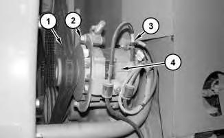
Illustration 1
g01753273
2. Remove wire harness (3). Remove bolts (2). Remove belts (1). Remove alternator (4) .
Installation Procedure
Illustration 2
g01753558
1. Position alternator (4). Install belts(1). Install bolts (2). Install wire harness (3). Refer to Testing and Adjusting, "Belt Tightning Chart" for the correct belt (1)adjustment .
2. Install the key. Turn the key for the battery disconnect switch to the ON position.
Copyright 1993 - 2020 Caterpillar Inc. All Rights Reserved. Private Network For SIS Licensees.
Product: MOTOR GRADER
Model: 140K MOTOR GRADER SZL
Configuration: 140K Motor Grader SZL00001-UP (MACHINE) POWERED BY C7 Engine
Disassembly and Assembly
12K, 140K, 140K Series 2 and 160K Motor Graders Engine Supplement
Media Number -KENR8442-03
Publication Date -01/12/2010
Battery - Remove and Install
SMCS - 1401-010
Removal Procedure
Disconnect batteries before performance of any service work.
Date Updated -13/12/2010
i03418702
1. Use two people in order to remove battery cover (1). The weight of the battery cover (1) is approximately 23 kg (50 lb).
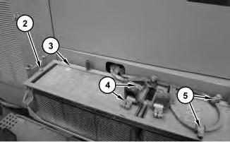
Illustration 2
g01773294
2. Remove clamps(5). Disconnect cables (4). Remove nuts(2). Remove bracket (3) .
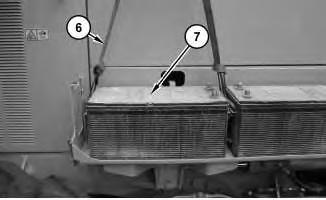
Illustration 3
g01773396
3. Attach a suitable lifting device (6). Remove battery (7). The approximate weight of battery (7) is 61 kg (135 lb).
Installation Procedure

4
1. Attach a suitable lifting device (6). Position battery (7). The approximate weight of battery (7) is 61 kg (135 lb).

5
2. Install bracket (3). Install nuts (2). Attach cables (4). Install clamps (5) .
6
3. Use two people in order to install battery cover (1). The approximate weight of the battery cover is 23 kg (50 lb).
Copyright 1993 - 2020 Caterpillar Inc. All Rights Reserved. Private Network For SIS Licensees. Fri Oct 2 22:32:02 UTC+0530 2020
Product: MOTOR GRADER
Model: 140K MOTOR GRADER SZL
Configuration: 140K Motor Grader SZL00001-UP (MACHINE) POWERED BY C7 Engine
Disassembly and Assembly
12K, 140K, 140K Series 2 and 160K Motor Graders Engine Supplement
Media Number -KENR8442-03
Publication Date -01/12/2010
Electric Starting Motor - Remove and Install
SMCS - 1453-010
Removal Procedure
Date Updated -13/12/2010
i03390583
Note: Put identification marks on all lines, on all hoses, on all wires, and on all tubes for installation purposes. Plug all lines, hoses, and tubes. This helps to prevent fluid loss and this helpsto keep contaminants from entering the system.
1. Turn the battery disconnect switch to the OFFposition.
2. Disconnect wires(1). Attach a suitable lifting device to electric starting motor (3). Use two people in order to support starting motor (3). The weight of electric starting motor (3) is approximately 27 kg (60 lb). Remove bolts (2) under electric starting motor (3). Remove electric starting motor (3).