

Previous Screen
Product: MOTOR GRADER
Model: 140H ES MOTOR GRADER 8KM
Configuration: 140H Motor Grader 8KM00001-UP (MACHINE) POWERED BY 3306 Engine
Disassembly and Assembly
12H, 140H and 160H Motor Graders Power Train Media
Wheel (Rear) - Remove and Install
SMCS - 4201-010; 4208-010; 4209-010
Removal Procedure
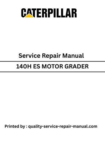
1. Use Tooling (D) (not shown) in order to raise the machine. Install Tooling (A) below the main frame, as shown.
2
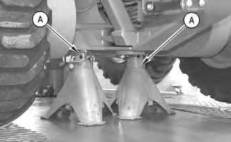
2. Attach a suitable lifting device to tire and rim (1). Secure the lifting device to a hoist.
3. Remove ten bolts (2) and washers from the rim.
4. Remove the tire and rim (1) from the wheel spindle. The weight of tire and the rim (1) is 182 kg (401 lb).
Installation Procedure
Illustration 3
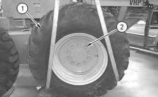
1. Attach a suitable lifting device to tire and rim (1). Secure the lifting device to a hoist.
2. Position the tire and rim (1) to the wheel spindle.
3. Install ten bolts (2) and the washers in the rim. Ten bolts (2) must be tightened to a torque of 700 ± 90 N·m (520 ± 66 lb ft).
Illustration 4
4. Remove the lifting device.
5. Raise the machine in order to remove Tooling (A) .
6. Lower the machine.
Copyright 1993 - 2025 Caterpillar Inc. All Rights Reserved. Private Network For SIS Licensees. Tue May 13 01:40:48 UTC+0530 2025
Previous Screen
Product: MOTOR GRADER
Model: 140H ES MOTOR GRADER 8KM
Configuration: 140H Motor Grader 8KM00001-UP (MACHINE) POWERED BY 3306 Engine
Disassembly and Assembly
12H, 140H and 160H Motor Graders Power Train
Media Number -SENR8548-14
Date -01/10/2011
Drive Sprocket - Remove and Install
SMCS - 4072-010
S/N - 2FM1-UP
S/N - 2GS1-UP
S/N - 2HS1-UP
S/N - 2LR1-UP
S/N - 2WR1-UP
S/N - 2ZK1-UP
S/N - 3AS1-UP
S/N - 3GM1-UP
S/N - 4ER1-UP
S/N - 4XM1-UP
S/N - 5HM1-UP
S/N - 5ZM1-UP
S/N - 6WM1-UP
S/N - 8JM1-UP
S/N - 8KM1-UP
S/N - 8MN1-UP
-12/10/2011
S/N - 9EJ1-UP
S/N - 9JM1-UP
S/N - 9TN1-UP
S/N - 9ZN1-UP
S/N - XZJ1-UP
S/N - XZK1-UP
Removal Procedure
Table 1
Required Tools
Start By:
A. Remove the tandem drive housings. Refer to Disassembly and Assembly, "Tandem and Cover - Remove and Install" for the correct procedure.
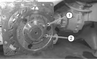
1 g00621016
1. Remove bolt (1), the washer, and the lock from nut (2) .
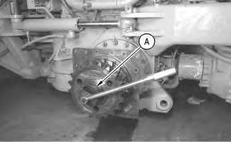
Illustration 2
g00621019
2. Use Tooling (A) in order to remove nut (2) from the drive shaft.
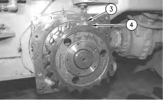
Illustration 3
g00621021
3. Remove sprocket (3) and sprocket (4) from the drive shaft. The weight of each sprocket is 15 kg (33 lb) for 12H and 140H motor graders and 23 kg (51 lb) for the 160H motor grader.
Installation Procedure
Illustration 4
g00621021
1. Position sprocket (3) on the drive shaft. Ensure that the hub of sprocket (3) is facing away from the final drives.
2. Position sprocket (4) on the drive shaft. Ensure that the hub of the sprocket (4) is facing toward the hub of sprocket (3) .
Illustration 5
g00621019
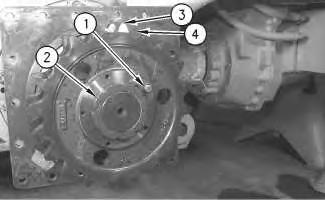
Illustration 6
g00637191
3. Install nut (2) that holds sprocket (4) and sprocket (3) on the drive shaft.
4. Use Tooling (A) in order to tighten nut (2) (not shown) to the proper torque. Use the following procedure.
a. Rotate the shaft and rap the sprockets while you tighten nut (2). This will preload the bearings. Tighten nut (2) to a torque of 12 ± 1 N·m (106 ± 9 lb in).
b. In order to check that the bearings are fully seated, reverse the direction of nut (2) for one locking position and rap the sprockets.
c. Tighten nut (2) to a final rolling torque of 4 ± 1 N·m (35 ± 9 lb in) above seal drag.
5. Install bolt (1), the washer, and the lock on nut (2) .
End By: Install the tandem drive housings. Refer to Disassembly and Assembly, "Tandem and Cover - Remove and Install" for the correct procedure. Copyright 1993 - 2025 Caterpillar Inc. All Rights Reserved.
Network For SIS Licensees. Tue May 13 01:41:03 UTC+0530 2025
This is the sample of the manual
Click on the download link for complete Manual
Previous Screen
Product: MOTOR GRADER
Model: 140H ES MOTOR GRADER 8KM
Configuration: 140H Motor Grader 8KM00001-UP (MACHINE) POWERED BY 3306 Engine
Disassembly and Assembly
12H, 140H and 160H Motor Graders Power Train
Media Number -SENR8548-14 Publication Date -01/10/2011
Final Drive - Assemble
SMCS - 4050-016
Assembly Procedure
Table 1
Required Tools
Tool
A 138-7573 Link Bracket 2
B 5P-4204 Wrench Assembly 1
C 6V-4876 Lubricant 1
D 8T-5096 Dial Indicator Gp 1
Date Updated -12/10/2011
i05371526
Note: Verify that all components of the power train are clean and free of foreign material prior to assembly.
Note: Check all of the components and all of the O-ring seals for wear or for damage. Replace the components, if necessary. Lubricate the O-ring seals lightly with the lubricant that is being sealed
Note: Use a suitable press in order to install the cones on the drive shafts and the cups. If necessary, only preheat the cones to 135 °C (275 °F) for no more than one hour. It is important to reseat the cone or the cup with a suitable driver after the bearing and adjacent parts have reached a uniform temperature.
1
2
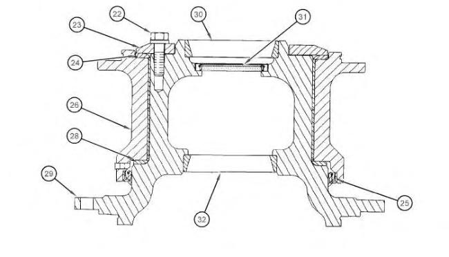
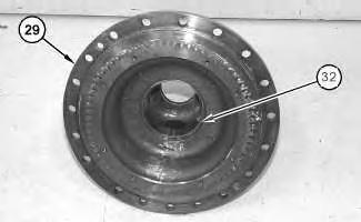
1. Lower the temperature of bearing cup (32) and install bearing cup (32) in housing (29). Check for full seating of the bearing cup with a Feeler Gauge.
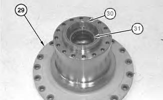
Illustration 3
2. Place housing (29) in a vertical position with the flange downward.
3. Install lip seal (31) in housing (29). The lip of the seal must face outward. Lubricate the lip seal (31) with the lubricant which is being sealed.
4. Lower the temperature of bearing cup (30) and install bearing cup (30) in housing (29). Check for full seating of the bearing cup with a Feeler Gauge.
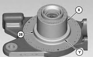
Illustration 4
5. Apply Tooling (C) onto thrust washer (28). Apply Tooling (C) onto surface (X) and surface (Y). Install thrust washer (18).
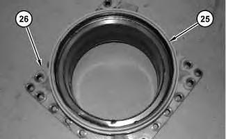
Illustration 5
6. Install lip seal (25) into housing (26).
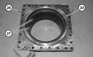
Illustration 6
7. Turn over housing (26). Install wear sleeves (27). The diagonal cuts that are in wear sleeves (27) are separated by 90°. Apply Tooling (C) onto thrust washer (24). Install thrust washer (24).
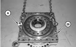
Illustration 7
g02783245
8. Use Tooling (A) and a suitable lifting device in order to install housing (26). The weight of housing (26) is approximately 54 kg (120 lb). Install shims (23A). Use a suitable soft hammer in order to drive the wear sleeves into housing (26) until the sleeves are flush with the top of the bore surface. Do not install the shims at this time.
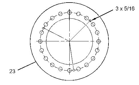
Illustration 8 g02783255
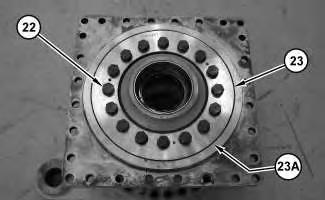
9. Drill three equally spaced 8 mm (5/16 inch) holes in retainer (23) if necessary. The holes must be centered on the existing bolt hole pattern and perpendicular to each surface.
10. Measure the thickness of retainer (23) at the three hole locations. Average the three measurements and record the result as Dimension (A).
9
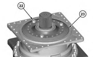
11. Install retainer (23). Install three of bolts (22). Tighten bolts (22) to a torque of 50 ± 7 N·m (37 ± 5 lb ft). Completely loosen bolts (22). Finger tighten bolts (22). Use Tooling (D) in order to measure the gap between the top surface of retainer (23) and the final drive housing at the three 8 mm (5/16 inch) hole locations. Record the measurement from each of the three locations as the nominal gap or Dimension (B).
12. Calculate the shim pack thickness for the three measurement locations by subtracting Dimension (A) from the Dimension (B) giving you Dimension (C). Remove bolts (22) and retainer (23).
10
13. Install a number of shims (23A) that is equal to Dimension (C) plus + 0.075 - 0.025 mm (+ 0.003 - 0.001 inch). Install retainer (23). Install bolts (22). Tighten bolts (22) to a torque of 270 ± 40 N·m (199 ± 30 lb ft).
11
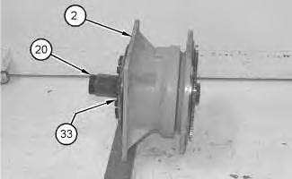
Illustration 12
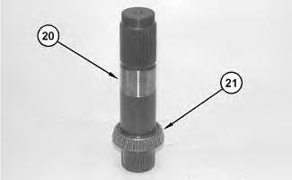
14. Preheat and install bearing cone (21) on drive shaft (20). Check for full seating of the cone with a Feeler Gauge. With the drive shaft in a vertical position, set the housing on bearing cone (21).
15. Start bearing cone (33) (not shown) on the top of drive shaft (20). Do not preheat this bearing cone. The bearing cone can be seated in position by using the sprocket during Step 17. Make sure that the bearing cone is seated in the cup.
16. Install drive shaft (20) in housing assembly (2).
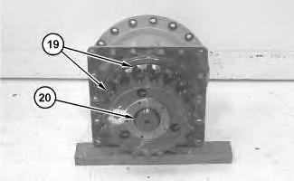
Illustration 13
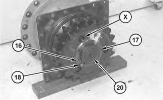
Illustration 14
17. Place the first sprocket (19) on drive shaft (20). The large diameter must face downward.
18. Place the second sprocket (19) on drive shaft (20). The hub must face downward and the large diameter must face upward. Ensure that the lubrication holes (X) for the spline are aligned.
19. Install nut (17) to the drive shaft (20). Rotate drive shaft (20) and hit the hub of sprockets (19) while nut (17) is being tightened to a torque of 11 ± 1 N·m (100 ± 10 lb in) above seal drag.
20. Loosen nut (17) by one locking position. Hit the hub of sprockets (19) again.
21. The final torque that is needed to rotate shaft (20) should be 2 ± 1 N·m (20 ± 10 lb in) or 3.95 ± 1.13 N·m (35 ± 10 lb in)above the seal drag depending on machine model.
Table 2
Model
120H, 120K, 135H 2.95 ± 1.13 N·m (26 ± 10 lb in)
12H, 12K, 140H, 140K, 143H, 160H, 160K, 163H 3.95 ± 1.13 N·m (35 ± 10 lb in)
Note: Refer to Testing and Adjusting, "Final Drive Bearings - Adjust" for bearing adjustments when the final drive is in chassis.
22. Install bolt (18), the washer, and lock (16) which holds nut (17) to the drive shaft (20). Tighten bolt (18) to a torque of 50 ± 10 N·m (37 ± 7 lb ft).
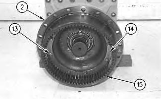
Illustration 15
g00621112
23. Position ring gear (15) to housing assembly (2).
24. Install bolts (13), the washers, and plates (14) in order to hold ring gear (15) to housing assembly (2). Tighten locking bolts (13) to a torque of 50 ± 10 N·m (37 ± 7 lb ft).
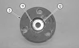
Illustration 16
g00621111
25. Install washer (12) and retaining ring (11) in planetary carrier (3).
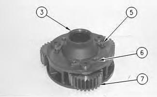
Illustration 17 g00621108
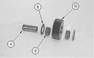
Illustration 18
g00621109
26. Install gear assemblies (7) and planetary shafts (4) in planetary carrier (3).
Note: Each gear assembly (7) consists of two washers (8), two roller assemblies (9), planetary gear (10), and planetary shaft (4).
27. Install retainers (6), the washers, and locking bolts (5) to planetary carrier (3) in order to hold planetary shafts (4) and gear assemblies (7) in planetary carrier (3). Tighten locking bolts (5) to a torque of 50 ± 10 N·m (37 ± 7 lb ft).
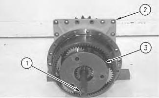
Illustration 19
g00621106
28. Install planetary carrier (3) in housing assembly (2).
29. Install sun gear shaft (1) in housing assembly (2).
This is the sample of the manual
Click on the download link for complete Manual
30. Repeat Steps 21 through 29 in order to assemble the remaining final drive.
End By:
a. Install the final drives. Refer to Disassembly and Assembly, "Final Drive - Install" for the correct procedure. Copyright 1993 - 2025 Caterpillar Inc. All Rights Reserved. Private Network For SIS Licensees.
Tue May 13 01:41:16 UTC+0530 2025