Previous Screen
Product: MOTOR GRADER
Model: 140B MOTOR GRADER 61S
Configuration: 140B MOTOR GRADER 61S00001-UP (MACHINE) POWERED BY 3306 ENGINE
Disassembly and Assembly
140B MOTOR GRADER
Media Number -SEBR0516-00
Publication Date -01/06/1979
Circle Centershift Housing
SMCS - 5210-11; 5210-12; 5210-15; 5210-16
Remove Circle Centershift Housing
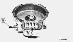
1. Drain the oil from the circle centershift housing.
Date Updated -11/10/2001
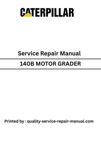
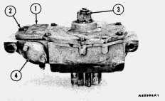
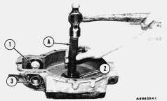
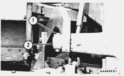
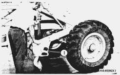
2. Remove the nut and washer that hold joint (1) on the shaft. Remove the joint. Remove the key from the shaft.
TYPICAL EXAMPLE
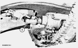
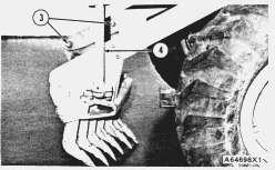
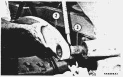
3. Remove four bolts (3), nuts and washers. Use two persons and remove circle centershift housing (2) and the shims from the rail. The weight is 74 lb. (34 kg). Put identification on the shims for correct assembly.
Install Circle Centershift Housing
TYPICAL EXAMPLE
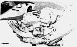
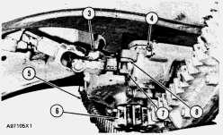
1. Put the four bolts through the circle centershift housing. Install the original shims (2) on the bolts.
2. Use two persons and put circle centershift housing (1) in position on the rail. Install the washer and nuts and tighten bolts (4) to a torque of 230 ± 15 lb.ft. (307 ± 20 N·m).
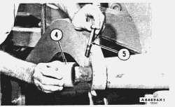
NOTE: The gear clearance (backlash) will decrease by an amount equal to approximately one half the thickness of shims removed.
3. Check the gear clearance (backlash) between drive pinion (6) and rack (5). Remove or add shims (2) so the gear clearance (backlash) is .002 to .010 in. (0.05 to 0.25 mm).
4. Install the key on the shaft. Connect joint (3) to the shaft. Install the washer and nut.
5. Fill the housing with oil. See LUBRICATION AND MAINTENANCE GUIDE.
6. Tighten jack screws (7) until they are just against the frame. Tighten locknuts (8).
Disassemble Circle Centershift Housing
start by:
a) remove circle centershift housing
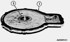
TYPICAL EXAMPLE
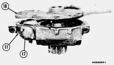
1. Remove cotter pin (3). Remove bolts (2) and cover (1) from the housing.
2. Remove the two bolts and cap (4) from the housing.
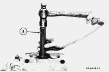
3. Remove bearing (5) from cover (1) with tooling (A).
TYPICAL EXAMPLE
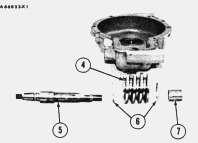
4. Remove nut (6) and sleeve (7) from the drive pinion.
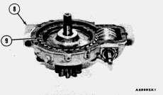
TYPICAL EXAMPLE
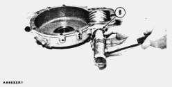
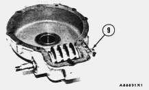
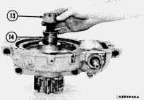
5. Lift housing (8) from the drive pinion. Remove gear (9) from the housing.
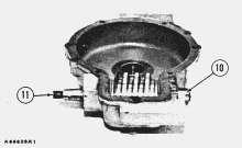
TYPICAL EXAMPLE
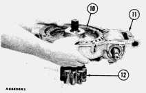
6. Remove the cotter pin and nut (10) from shaft (11).
TYPICAL EXAMPLE
7. Use a plastic hammer and remove shaft (11) and the seal from the housing.
8. Remove the key from the shaft. Remove the sleeve from the housing.
9. Remove worm (13) and thrust washers (12) from the housing.
TYPICAL EXAMPLE
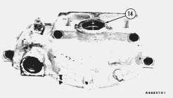
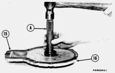
10. Remove seal (14) from the housing.
TYPICAL EXAMPLE
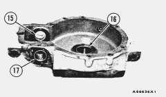
11. Remove bearings (15), (16) and (17) from the housing with tooling (A).
Assemble Circle Centershift Housing
TYPICAL EXAMPLE
1. Install bearings (1), (2) and (3) in the housing with tooling (A).
2. Install the seal in the housing with tooling (A). Make sure the lip of the seal is toward the drive pinion gear.
TYPICAL EXAMPLE
3. Install thrust washers (6) and worm (4) in the housing.
4. Install the key on shaft (5). Install the shaft in the housing and through the worm. Install sleeve (7).
This is the sample of the manual
Click on the download link for complete Manual
TYPICAL EXAMPLE
5. Use a socket of the correct size and install seal (9) for shaft (5). The lip of the seal must be tow!rd the inside of the housing.
TYPICAL EXAMPLE
6. Install nut (9) and the cotter pin on the shaft. Install the cap on the end of the shaft.
TYPICAL EXAMPLE
7. Install gear (10) in the housing. Install the gear and housing (11) on to drive pinion (12) as shown.
TYPICAL EXAMPLE
8. Install sleeve (14) and nut (13) on the drive pinion.
9. Put gasket (15) in position on the cover. Make an alignment of the hole in the bearing with the grease hole in the cover. Install the bearing in cover (16) with tooling (A).
TYPICAL EXAMPLE
10. Install cover (16) on housing (11).
11. Install cap (17) on the housing.
TYPICAL EXAMPLE
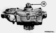
12. Install cotter pin (18) that holds the nut in position. end by:
a) install circle centershift housing Copyright 1993 - 2025 Caterpillar Inc. All Rights Reserved.
Previous Screen
Product: MOTOR GRADER
Model: 140B MOTOR GRADER 61S
Configuration: 140B MOTOR GRADER 61S00001-UP (MACHINE) POWERED BY 3306 ENGINE
Disassembly and Assembly
140B MOTOR GRADER
Media Number -SEBR0516-00
Publication Date -01/06/1979
Scarifier Frame And Drawbar
SMCS - 6162-12; 6162-11
Remove Scarifier Frame And Drawbar
1. Lower the scarifier to the ground.
Date Updated -11/10/2001
2. Remove bolt (1) and collar (2) from the shaft on the right side of the machine.
3. Disconnect lift links (4) from each side of the scarifier.
4. Remove two bolts (3) from the drawbar on the left side. Hold the drawbar up with a hoist.
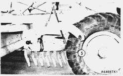
5. Fasten a hoist to the scarifier (5) and remove the scarifier. The weight is 700 lb. (320 kg).
Install Scarifier Frame And Drawbar
1. Fasten a hoist to scarifier (1) and put it in position under the machine.
2. Install drawbar (2) on shaft (3) on the right side of the machine.
3. Install collar (4), bolt (5) and the nut that holds the drawbar in position.
4. Put the drawbar in place on the scarifier on the left side and install bolts (6).
5. Connect lift links (7) on each side of the machine.
Previous Screen
Product: MOTOR GRADER
Model: 140B MOTOR GRADER 61S
Configuration: 140B MOTOR GRADER 61S00001-UP (MACHINE) POWERED BY 3306 ENGINE
Systems Operation
140B MOTOR GRADER
Media Number -SEBR0516-00
Publication Date -01/06/1979
Power Control Systems Operation
SMCS - 6162-12; 6162-11
Power Control
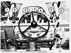
POWER CONTROL LEVERS
Date Updated -11/10/2001
1. Left side blade lift or lower lever. 2. Scarifier lift or lower lever. 3. Circle reverse lever. 4. Circle center shift lever. 5. Front wheel lean lever. 6. Right side blade lift or lower lever.
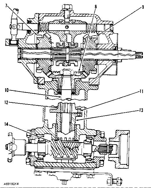
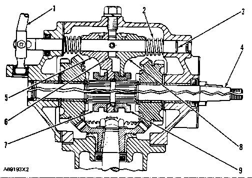
The power control uses engine power to move the implements and lean the front wheels. A shaft is connected by splines to the engine flywheel. This shaft goes through the center of the transmission upper shaft and turns the drive shaft for the power control.
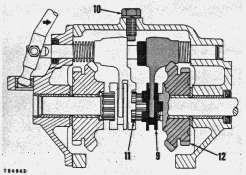
The drive shaft turns worm shaft (14). The worm shaft turns a worm gear which is fastened to drive coupling (13) by splines. Shear pin (11) sends the power to driven coupling (12) which is fastened by splines to shaft (10). The shear pin protects the power control components from overloads.
Shaft (10) turns bevel gear (8) that is engaged with transfer gears (7) and (9). These transfer gears give power to the transfer gears for the other clutches. The transfer gears at the front of the housing turn in opposite directions to their respective transfer gear at the rear of the housing.
The clutches, when engaged, send the power from a transfer gear to an output shaft. The blade lift and lower clutches are different from the other clutches.
POWER CONTROL
7. Transfer gear. 8. Bevel gear. 9. Transfer gear. 10. Shaft. 11. Shear pin. 12. Driven coupling. 13. Drive coupling. 14. Worm shaft.
Power Control Clutches
Blade Lift or Lower Clutches
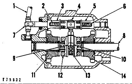
The blade lift or lower lever (1) is connected to shifter shaft (7) for both of the blade lift clutches. Shifter fork (4) is fastened to the shaft by a pin. The shifter fork fits over pressure plate (9) and (10). The pressure plates are held apart by springs (13). The pressure plates fit in the groove in clutch (12).
BLADE LIFT OR LOWER CLUTCHES
1. Blade lift or lower lever. 2. Spring. 3. Cartridge assembly. 4. Shifter fork. 5. Cartridge assembly. 6. Spring. 7. Shifter shaft. 8. Output shaft. 9. Pressure plate. 10. Pressure plate. 11. Transfer gear. 12. Clutch. 13. Springs. 14. Transfer gear.
When the clutches are not engaged, springs (2) and (6) keep clutch (12) in its center position between transfer gears (11) and (14). The force of springs (13) keeps pressure plate (9) and (10) against the side of the groove in clutch (12). This causes a braking action and keeps blade drift to a minimum.
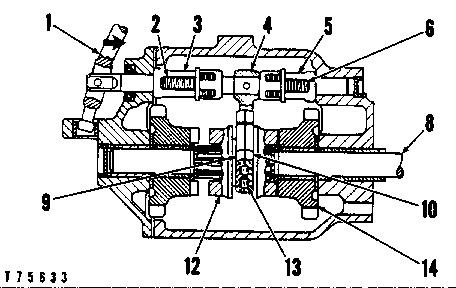
When the blade control lever is moved forward to the BLADE LOWER position, shifter fork (4) moves pressure plate (9) toward pressure plate (10). This compresses springs (13) and removes the braking force on one side of the clutch groove. This lets output shaft (8) turn freely when the jaws of the clutch engage the jaws on gear (14). When the clutch is engaged with the transfer gear, power is sent through the clutch to the output shaft.
BLADE LOWER CLUTCH ENGAGED
1. Blade lift or lower lever. 2. Spring. 3. Cartridge assembly. 4. Shifter fork. 5. Cartridge assembly. 6. Spring. 8. Output shaft. 9. Pressure plate. 10. Pressure plate. 12. Clutch. 13. Springs. 14. Transfer gear.
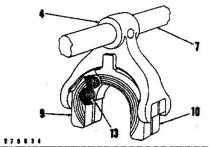
SHIFTER FORK AND BRAKE
4. Shifter fork. 7. Shifter shaft. 9. Pressure plate. 10. Pressure plate. 13. Springs.
Scarifier, Circle Reverse, Side Shift and Wheel Lean Clutches
CLUTCH FOR SCARIFIER, CIRCLE REVERSE, SIDE SHIFT AND WHEEL LEAN
1. Control lever. 2. Springs. 3. Shifter shaft. 4. Output shaft. 5. Rear shifter fork. 6. Collar. 7. Clutch rear collar. 8. Front shifter fork. 9. Clutch front collar.
Control lever (1) is connected to shifter shaft (3). Two shifter forks (5) and (8) are installed on the shifter shaft. The forks are held in place by springs (2) and collar (6). The collar is fastened to the shaft by a pin. The shifter forks fit in the grooves in clutch collars (7) and (9). The clutch collars slide on splines on output shaft (4). The shifter forks and collars work together to give power rotation of the output shaft in either direction.
This is the sample of the manual
Click on the download link for complete Manual
When the clutches are not engaged, lugs on rear shifter fork (5) are engaged with notches in clutch front collar (9). This gives a mechanical lock so that the implements can not move.
CLUTCH ENGAGED
9. Clutch front collar. 10. Setscrew. 11. Retainer ring. 12. Transfer gear.
When the control lever is moved toward the front, the mechanical lock is released first. With additional movement of the control lever, the jaws on clutch front collar (9) engage the jaws on transfer gear (12). This causes the output shaft to rotate.
Setscrew (10) and retainer ring (11) are stops for the clutch collars. These stops prevent movement of one collar when the other collar is moved to the engaged position.
Copyright 1993 - 2025 Caterpillar Inc. All Rights Reserved. Private Network For SIS Licensees.
Tue May 13 01:36:39 UTC+0530 2025