

Previous Screen
Product: MOTOR GRADER
Model: 135H NA MOTOR GRADER 3YK
Configuration: 135H Motor Grader 3YK00001-UP (MACHINE) POWERED BY 3116 Engine
Disassembly and Assembly
446 and 446B Backhoe Loaders, Lexion 450 Combine, 3114 and 3116 Engines, IT18F Integrated Toolcarrier, D6M Track-Type Tractor and 928F, 950F and 950G Wheel Loaders
Media Number -SENR3611-18
Fuel Shutoff Solenoid - Remove and Install
SMCS - 1259-010
Removal Procedure
Table 1
Required Tools
Tool Part Number Part Description Qty
A 9U-5120 Spanner Wrench(1) 1 (1) This tool is part of the 128-8822 Fuel System and Governor Tool Group.
NOTICE
Keep all parts clean from contaminants.
Contaminants may cause rapid wear and shortened component life.
NOTICE
Care must be taken to ensure that fluids are contained during performance of inspection, maintenance, testing, adjusting, and repair of the product. Be prepared to collect the fluid with suitable containers before opening any compartment or disassembling any component containing fluids.
Refer to Special Publication, NENG2500, "Dealer Service Tool Catalog" for tools and supplies suitable to collect and contain fluids on Cat products.
Dispose of all fluids according to local regulations and mandates.
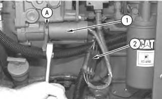
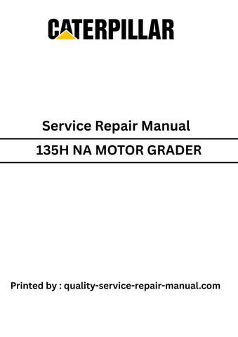
Illustration 1
g00585831
1. Disconnect the harness assembly (2) from fuel shutoff solenoid (1).
2. Use Tooling (A) to remove the fuel shutoff solenoid from the governor.
3. Remove the O-ring seal from the shutoff solenoid .
Installation Procedure
Table 2
Required Tools
Tool Part Number Part Description Qty A 9U-5120 Spanner Wrench(1) 1 (1) This tool is part of the 128-8822 Fuel System and Governor Tool Group.
NOTICE
Keep all parts clean from contaminants.
Contaminants may cause rapid wear and shortened component life.
NOTICE
Care must be taken to ensure that fluids are contained during performance of inspection, maintenance, testing, adjusting, and repair of the product. Be prepared to collect the fluid with suitable containers before opening any compartment or disassembling any component containing fluids.
Refer to Special Publication, NENG2500, "Dealer Service Tool Catalog" for tools and supplies suitable to collect and contain fluids on Cat products.
Dispose of all fluids according to local regulations and mandates.
1. Inspect the O-ring seal on the fuel shutoff solenoid. If the O-ring seal is worn or damaged, use new parts for replacement.
2. Install the O-ring seal on the fuel shutoff solenoid.
3. Install the fuel shutoff solenoid in the governor. Use Tooling (A) and a suitable torque wrench to tighten the fuel shutoff solenoid to the following torque 30 ± 5 N·m (22 ± 4 lb ft).
4. Connect the harness assembly to the fuel shutoff solenoid.
Previous Screen
Product: MOTOR GRADER
Model: 135H NA MOTOR GRADER 3YK
Configuration: 135H Motor Grader 3YK00001-UP (MACHINE) POWERED BY 3116 Engine
Disassembly and Assembly
446 and 446B Backhoe Loaders, Lexion 450 Combine, 3114 and 3116 Engines, IT18F Integrated Toolcarrier, D6M Track-Type Tractor and 928F, 950F and 950G Wheel Loaders
Media
-27/05/2009
Fuel Injection Control Linkage - Remove
SMCS - 1298-011
Removal Procedure
Table 1
Required Tools
Tool Part Number Part Description Qty
A 136-4149 Governor Pliers 1
Start By:
a. Remove the rocker shaft and the pushrods. Refer to Disassembly and Assembly, "Rocker Shaft and Pushrod - Remove".
NOTICE
Keep all parts clean from contaminants. Contaminants may cause rapid wear and shortened component life.
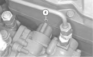
Illustration 1
g00613071
1. Remove clip (4). Clip (4) is located between the governor and the cylinder head.
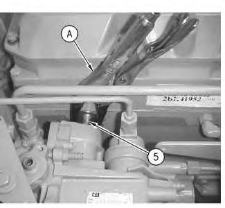
Illustration 2
g00655975
2. Use Tooling (A) to slide tube assembly (5) into the cylinder head.
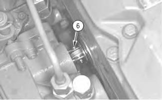
Illustration 3
g00613149
3. Remove the clip and use Tooling (A) to remove the clevis pin (6). Clevis pin (6) connects the governor to the control lever of the fuel injection control linkage.
Note: Clevis pin (6) must stay with the governor in order to be adjusted.
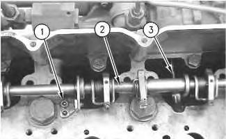
Illustration 4
g00630566
4. Remove bolts (1) and remove fuel injection control linkage (2). Control lever (3) connects the fuel injection control linkage (2) to the governor.
Note: For information on the inspection procedure for control lever (3), refer to Special Instruction, REHS0601, "Inspection and Modification of the 102-7459 Fuel Injection Control Linkage and the 4P-9048 Fuel Injection Control Linkage".
Copyright 1993 - 2025 Caterpillar Inc. All Rights Reserved. Private Network For SIS Licensees.
Tue May 13 01:33:06 UTC+0530 2025
Previous Screen
Product: MOTOR GRADER
Model: 135H NA MOTOR GRADER 3YK
Configuration: 135H Motor Grader 3YK00001-UP (MACHINE) POWERED BY 3116 Engine
Disassembly and Assembly
446 and 446B Backhoe Loaders, Lexion 450 Combine, 3114 and 3116 Engines, IT18F Integrated Toolcarrier, D6M Track-Type Tractor and 928F, 950F and 950G Wheel Loaders Media
-SENR3611-18
Turbocharger - Install
SMCS - 1052-012
Installation Procedure
Table 1
Required Tools
Tool Part Number Part Description Qty
A 5P-3931 Anti-Seize Compound 1
NOTICE
Keep all parts clean from contaminants.
Contaminants may cause rapid wear and shortened component life.
Note: For information on the reusability of components of the turbocharger, refer to Guideline For Reusable Parts And Salvage Operations, SEBF8018, "Turbochargers". For information on the salvage of components of the turbocharger, refer to Guideline For Reusable Parts And Salvage Operations, SEBF8071, "Procedures to Salvage Turbocharger Components".
1. Inspect the turbocharger gasket for wear or damage. If the turbocharger gasket is worn or damaged, use a new part for replacement.
2. Apply Tooling (A) on the threads of the mounting studs for the turbocharger.
This is the sample of the manual
Click on the download link for complete Manual
1
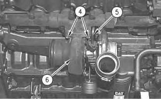
3. Position the turbocharger gasket and turbocharger (6) on the exhaust manifold. Install nuts (4) and tighten nuts (4) to a torque of 54 ± 5 N·m (40 ± 4 lb ft).
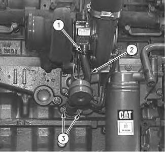
Illustration 2
g00617515
4. Inspect the gaskets for oil supply tube assembly (5) and oil drain tube assembly (2). If the gaskets are worn or damaged, use a new part for replacement.
5. Position oil drain tube assembly (2) and the gasket on turbocharger (6). Install bolts (1) on the turbocharger and install bolts (3) on the cylinder block.
6. Install the gasket for oil supply tube assembly (5) and connect oil supply tube assembly (5) to turbocharger (6).
Tue May 13 01:33:21 UTC+0530 2025