

Product: MOTOR GRADER
Model: 12H NA MOTOR GRADER 2WR
Configuration: 12H NA Motor Grader 2WR00001-UP (MACHINE) POWERED BY 3306 Engine
Disassembly and Assembly
26SI Series Alternator
i01167078
Alternator - Assemble
SMCS - 1405-016
Assembly Procedure
Note: Cleanliness is an important factor. Before assembly, all partsshould be thoroughly cleaned in cleaning fluid. Allow the parts to air dry. Wiping clothsor ragsshould not be used to dry parts. Lint may be deposited on the partswhich may cause later trouble. Inspect all parts. If any parts are worn or damaged, use new parts for replacement.
Note: Do not strike the diodes. The shock of such an impact can damage the diodes. Use proper tools in order to pressthe diodesin the mountings.

Illustration 1
1. Install 3 diodes (11) in heat sink (12) .
g00628072
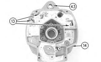
Illustration 2
g00628068
Note: Do not strike the bushing. Shocksfrom striking the housing can cause damage.
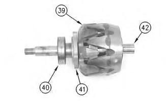
Illustration 3

Illustration 4
g00628063
7. Press housing (31) on rotor (39) and bearing (40) .
8. Install 4 screws (38) in housing (31) .
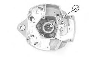
Illustration 5
g00628057
Note: Do not strike the bearing. Shocksfrom striking the housing can cause damage.
9. Install the inner race. Press bearing (37) into the housing.
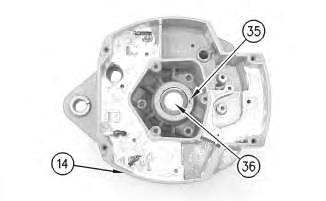
Illustration 6
10. Press cap (36) in housing (14) .
g00628043

Illustration 7
g00628041
11. Install the coil and support (34) in housing (14). Guide the field leadsand the grommet through the hole as the coil isinstalled in housing (14). Install 3 screws (33) .
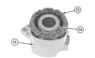
Illustration 8
g00628037
12. Press the stator (32) and housing (14) together. Guide the stator leads and the grommet through the hole as the stator is installed in housing (14) .
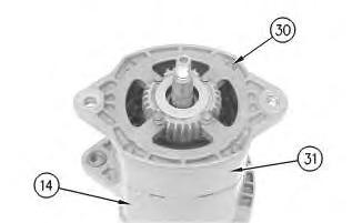
Illustration 9
g00628035
Note: Do not damage exposed stator windings or field windings. Bumping the windings or scraping the windings may break the insulation. Broken insulation may create a short circuit or a ground.
13. Join housing (31) and housing (14). Install 4 bolts (30) .
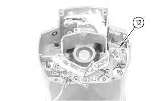
Illustration 10
g00627853
Note: Many of the alternator's internal components are covered with dielectric grease. If the grease is removed, reapply the grease.
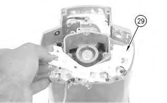
Illustration 11
14. Install Insulator (29). Install the heat sink and diode assembly (12) in housing (14) .
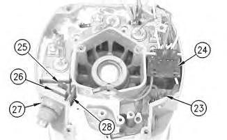
Illustration 12
15. Install separator (28) .
16. Install alternator output terminal (27). Install insulator (26). Install the nut and washer (25) .
17. Install diode trio (24) and install screw(23) .
This is the sample of the manual
Click on the download link for complete Manual
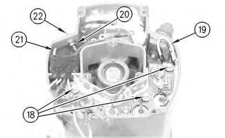
Illustration 13
18. Install the 3 screws and insulators (18). Connect wire (19) .
19. If the "R" terminal is used, install the following components: nut (20), lead (21), the washer and terminal (21) .

Illustration 14
g00627820
20. Install the screw and insulator (16). Connect capacitor lead (17) .
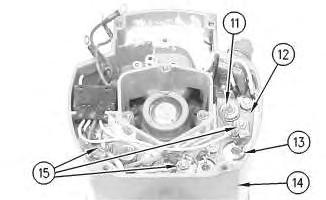
Illustration 15
g00627810
Note: The 3 output diodes (11) are located in heat sink (12). These diodes are identical in polarity. Diode (11) has red insulation on the wire. The 3 ground diodes (13) are located in housing (14). These diodesare identical in polarity. Diode (13) hasblack insulation on the wire.
21. Connect 6 diode leads. Connect 3 phase leads. Connect 3 stator phase leads. Install 3 nuts(15).
Table 1
Alternator Ground
Current Flowof the Output Diodes
Lead to the Heat Sink
Negative
Current Flowof the Ground Diodes
Housing to the Lead Red Wire Black Wire
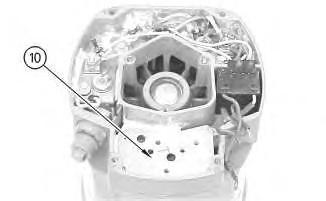
Illustration 16
22. Install mounting plate (10).
g00627808
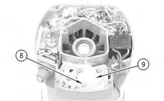
Illustration 17
g00627804
23. Install regulator (9) .
24. Install grounded mounting screw (8) .
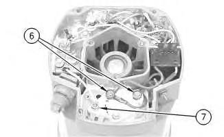
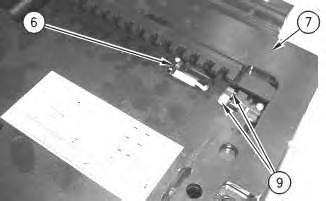
Illustration 18
25. Install 2 insulated screws (6). Connect the 3 leads.
Note: The regulator and the mounting plate are coated with dielectric grease. If the grease is removed, reapply the grease.
26. Install nut (7) and connect the wire.
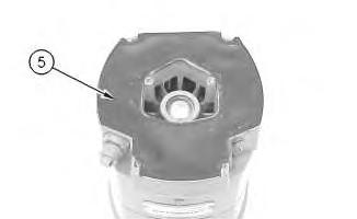
Illustration 19
27. Install gasket (5) .
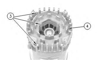
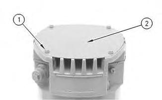
Illustration 20
28. Position cover (4). Install 7 screws (3) .
g00627792
21
29. Position plate (2). Install 4 screws (1) .
30. Install the fan, the pulley, the washer, and the pulley nut.
Product: MOTOR GRADER
Model: 12H NA MOTOR GRADER 2WR
Configuration: 12H NA Motor Grader 2WR00001-UP (MACHINE) POWERED BY 3306 Engine
Disassembly and Assembly
26SI Series Alternator Media
i01167081
Alternator - Disassemble
SMCS - 1405-015
Disassembly Procedure
Table 1
Required Tools
Start By:
A. Remove the alternator. Refer to Disassembly and Assembly, "Alternator - Remove" for the machine that is being serviced.
Note: Cleanliness is an important factor. Before the disassembly procedure, the exterior of the component should be thoroughly cleaned. This will help to prevent dirt from entering the internal mechanism.
1. Remove the pulley nut, the washer, the pulley, and the fan.
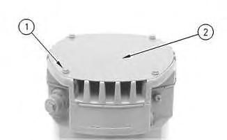
Illustration 1
2. Remove 4 screws (1). Remove plate (2) .
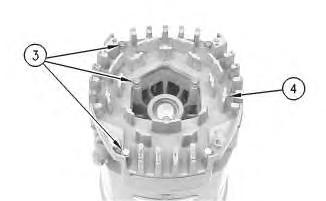
Illustration 2
3. Remove 7 screws (3). Remove cover (4) .
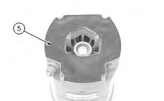
Illustration 3
4. Remove gasket (5) .
Illustration 4
5. Remove 2 insulated screws(6). Remove the 3 leads.
Note: The regulator and the mounting plate are coated with dielectric grease. If the grease is removed, reapply the grease.
6. Remove nut (7) .
Illustration 5
7. Remove grounded mounting screw (8) .
8. Remove regulator (9) .
Illustration 6
g00627808
9. Remove mounting plate (10). The mounting plate may be stuck to the regulator.

Illustration 7
g00627810
Note: The 3 output diodes (11) are located in heat sink (12). These diodes are identical in polarity. Diode (11) has red insulation on the wire. The 3 ground diodes (13) are located in housing (14). These diodesare identical in polarity. Diode (13) hasblack insulation on the wire.
10. Remove 3 nuts (15). Disconnect 3 stator phase leads. Disconnect 3 phase leads. Disconnect 6 diode leads.
Table 2
Alternator Ground
Negative
Current Flowof the Output Diodes
Current Flowof the Ground Diodes
Lead to the Heat Sink Housing to the Lead Red Wire Black Wire
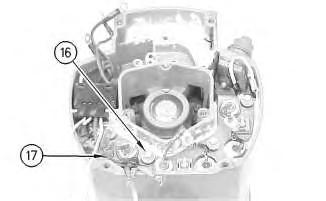
Illustration 8
g00627820
11. Remove the screw and insulator (16). Disconnect capacitor lead (17) .
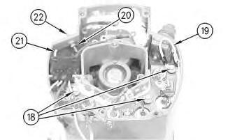
Illustration 9
g00627832
12. Remove the 3 screws and insulators (18). Disconnect wire (19) .
13. If the "R" terminal is used, remove the following components: nut (20), lead (21), the washer and terminal (21) .
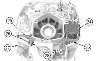
Illustration 10
14. Remove screw(23) and remove diode trio (24) .
15. Remove the nut and washer (25). Remove insulator (26). Remove alternator output terminal (27) .
16. Remove separator (28) .
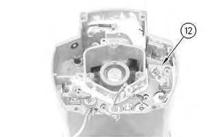
Illustration 11
g00627853
Note: Many of the alternator's internal components are covered with dielectric grease. If the grease is removed, reapply the grease.
Illustration 12
g00627855
17. Remove the heat sink and diode assembly (12) from housing (14). Insulator (29) may be stuck to heat sink (12) .
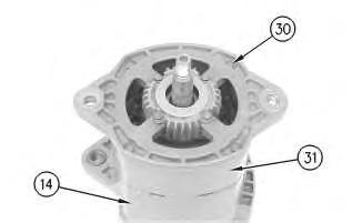
Illustration 13
g00628035
Note: Do not damage exposed stator windings or field windings. Bumping the windings or scraping the windings may break the insulation. Broken insulation may create a short circuit or a ground.
18. Remove 4 bolts (30). Carefully separate housing (31) from housing (14) .
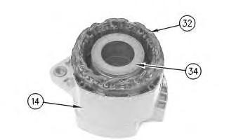
Illustration 14
g00628037
19. Pull apart stator (32) and housing (14). Guide the stator leads and the grommet through the hole asthe stator is removed from housing (14) .
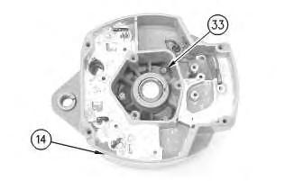
Illustration 15
g00628041
20. Remove 3 screws (33). Remove the coil and support (34) from housing (14). Guide the field leads and the grommet through the hole as the coil is removed from housing (14) .
Illustration 16
g00628043
21. Position a small screwdriver in slot (35). Pry cap (36) from housing (14) .
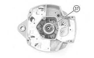
Illustration 17
g00628057
Note: Do not strike the bearing. Shocksfrom striking the housing can cause damage.
22. Wipe the excess grease from the bearing well. Press bearing (37) into the housing. Remove the inner race.
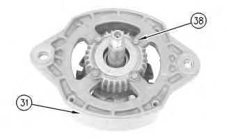
Illustration 18
23. Remove 4 screws (38) from housing (31) .
g00628063
24. Lift rotor (39) and bearing (40) from housing (31) .
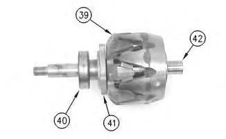
Illustration 19
25. Pull bearing (40) from rotor (39) .
26. Pull retainer (41) from rotor (39) .
27. Pull collar (42) from rotor (39) .
Illustration 20
g00628068
Note: Do not strike the bushing. Shocksfrom striking the housing can cause damage.
28. Press bushing (43) from housing (14) .
Note: Do not strike the diodes. The shock of such an impact can damage the diodes. Use proper tools in order to pressor pull the diodes from the mountings. As much as 890 N(200 lb) of force may be needed to remove a diode.
29. Remove 3 diodes (13) from housing (14) .
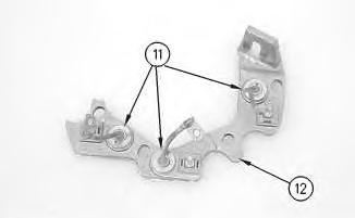
Illustration 21
30. Remove diode (11) from heat sink (12) .
g00628072
Copyright 1993 - 2021 Caterpillar Inc. All Rights Reserved. Private Network For SIS Licensees.
Sun May 2 11:04:06 UTC+0530 2021
Product: MOTOR GRADER
Model: 12H NA MOTOR GRADER 2WR
Configuration: 12H NA Motor Grader 2WR00001-UP (MACHINE) POWERED BY 3306 Engine
Disassembly and Assembly
Comfort Series Seat For Caterpillar Machines
Media Number -RENR2165-12
Air Suspension With Air Valve
Knob Height Adjustment -
i01723170
Assemble
SMCS - 7324-016-AJ
Assembly Procedure
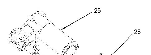

Illustration 1 g00891451
1. Install compressor assembly (25) to mount (26). Make sure that compressor assembly (25) is seated firmly in mount (26) .
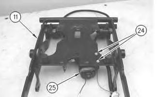
Illustration 2
2. Install bolts (24) in order to attach compressor assembly (25) to scissor assembly (11) .
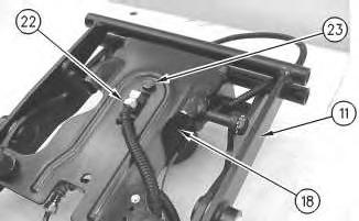
Illustration 3
g00872043
Improper assembly of parts that are spring loaded can cause bodily injury.
To prevent possible injury, follow the established assembly procedure and wear protective equipment.
3. Install bolt (23) in order to attach spring assembly (18) to scissor assembly (11). Attach hose assembly (22) to spring assembly (18) .
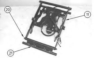
Illustration 4
g00872037
4. Install shaft (20) in order to attach toggle assembly (21) to scissor assembly (11). Tighten the two nutsfor shaft (20) to a torque of 15 ± 3 N·m (11 ± 2 lb ft).
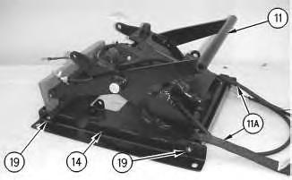
Illustration 5
g00872031
5. Install shaft assemblies (19) in order to attach tether straps (11A) and scissor assembly (11) to housing assembly (14). Tighten the nuts on shaft assemblies(19) to a torque of 20 ±5 N·m (15 ± 4 lb ft). Install blocking in order to prevent scissor assembly (11) from falling.
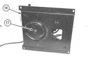
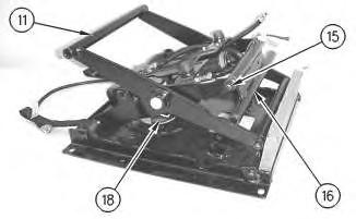
Illustration 7 g00872020
6. Install screw(17) in order to attach housing assembly (14) to spring assembly (18) .
7. Install shaft (15) in order to attach toggle assembly (16) to scissor assembly (11). Tighten the two nutsfor shaft (15) to a torque of 15 ± 3 N·m (11 ± 2 lb ft).
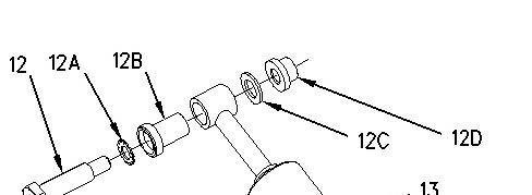
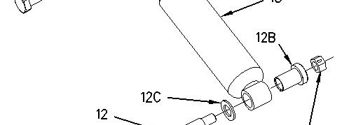
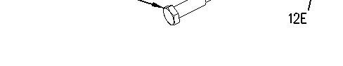
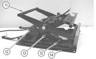
Illustration 9
g00872007
8. Install bearings (12B) to shock absorber (13) .
9. Install bolts (12) in order to attach shock absorber (13) to scissor assembly (11) and housing assembly (14). Remove the blocking.
Note: Illustration 8 shows the location of lockwasher (12A), bearings(12B), washers (12C), nut (12D), and locknut (12E) .
10. Repeat Steps 8 and 9 if the seat is equipped with a shock absorber on the opposite side.

Illustration 10
g00871994
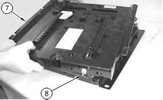
11. Connect harness assemblies(9) and hose assembly (10) to air valve (8) .
This is the sample of the manual
Click on the download link for complete Manual
11
g00871971
12