

PreviousScreen
Product: MOTOR GRADER
Model: 12H ES MOTOR GRADER 2GS
Configuration: 12H Motor Grader 2GS00001-UP (MACHINE) POWERED BY 3306 Engine
Disassembly and Assembly
3304B and 3306B Engines for Caterpillar Built Machines Media Number -SENR5598-09
Air Compressor - Remove and Install
SMCS - 1803-010
Removal Procedure
Do not disconnect the air lines until the air pressure in the system isat zero. If hose is disconnected under pressure it can cause personal injury.
NOTICE
Keep all parts clean from contaminants. Contaminants may cause rapid wear and shortened component life.
NOTICE
Care must be taken to ensure that fluidsare contained during performance of inspection, maintenance, testing, adjusting and repair of the machine. Be prepared to collect the fluidwith suitable containers
before opening any compartment or disassembling any component containing fluids.
Refer to Special Publication, NENG2500, "Caterpillar Tools and Shop Products Guide", for tools and supplies suitable to collect and contain fluids in Caterpillar machines.
Dispose of all fluids according to local regulationsand mandates.
1. Remove the air pressure from the air tank and drain the coolant from the cooling system.
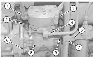
Illustration 1
2. Disconnect hose (1), (2) and (9) from the air compressor. Remove tube (4) from the air compressor.
3. Remove bolt (5) and the washer. Remove clamp (7) from the breather tube. Move the breather tube aside.
4. Remove three bolts (3) and the washersthat hold the air compressor to the timing gear housing.
5. Remove two bolts (6) and remove air compressor (8) and the gasket from the engine.
Installation Procedure
NOTICE
Keep all parts clean from contaminants.
Contaminants may cause rapid wear and shortened component life.
Note: Check the condition of the gaskets and O-ring seals. If gaskets or O-ring sealsare damaged, use newparts for replacement.
2
1. Use three bolts(3) and the washers to install air compressor (8). Apply 4C-4030 Thread Lock Compound to the threads of two bolts (6). Torque bolts (6) to 160 ± 30 N·m (118 ± 22 lb ft).
2. Install clamp (7) for the breather tube with bolt (5) and the washer.
3. Install tube (4) and connect hoses(9), (2) and (1) to air compressor (8) .
Thu Jan 2 17:25:40 UTC+0530 2020
PreviousScreen
Product: MOTOR GRADER
Model: 12H ES MOTOR GRADER 2GS
Configuration: 12H Motor Grader 2GS00001-UP (MACHINE) POWERED BY 3306 Engine
Disassembly and Assembly
3304B and 3306B Engines for Caterpillar Built Machines
Media Number -SENR5598-09
-01/01/2013
Automatic Timing Advance - Assemble
SMCS - 1272-016
Assembly Procedure
NOTICE
Keep all parts clean from contaminants.
Contaminants may cause rapid wear and shortened component life.
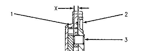


Illustration 1 g00476382
1. If dowels(3) were removed from the gear hub, installation dimension (X) is9.00 ± 0.50 mm (.354 ± .020 inch).
2. Install seals (4) and (5) .
3. Put gear (1) in position on hub assembly (2) .
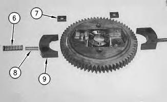
Illustration 2 g00476383
4. Install slide (7), weight (9) and springs (6) and (8) on each side of the assembly.
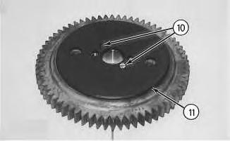
Illustration 3 g00476385
5. Install plate (11) with two screws (10) .
End By: Install the automatic timing advance unit. Refer to Disassembly and Assembly, "Automatic Timing Advance - Install".
Copyright 1993 - 2020 Caterpillar Inc. All Rights Reserved. Private Network For SIS Licensees. Thu Jan 2 16:56:33 UTC+0530 2020
PreviousScreen
Product: MOTOR GRADER
Model: 12H ES MOTOR GRADER 2GS
Configuration: 12H Motor Grader 2GS00001-UP (MACHINE) POWERED BY 3306 Engine
Disassembly and Assembly
3304B and 3306B Engines for Caterpillar Built Machines Media Number -SENR5598-09
Automatic Timing Advance - Disassemble
SMCS - 1272-015
Disassembly Procedure
Start By:
A. Remove the automatic timing advance unit. Refer to Disassembly and Assembly, "Automatic Timing Advance - Remove".
NOTICE
Keep all parts clean from contaminants.
Contaminants may cause rapid wear and shortened component life.

Illustration 1
1. Remove two screws (1) and plate (2) .
NOTICE
The weights are heldinposition with two springs for each weight that is under compression. Carefully remove the weights and the springsin order to help prevent possible injury.

Illustration 2
g00476293
2. Remove springs (3) and (5), weight (6) and slide (4) from each side of the assembly.


Illustration 3 g00476294
3. If necessary, remove gear (7). Remove seals (8) and (9) .
Copyright 1993 - 2020 Caterpillar Inc. All Rights Reserved. Private Network For SIS Licensees. Thu Jan 2 16:56:15 UTC+0530 2020
This is the sample of the manual Click on the download link for complete manual
PreviousScreen
Product: MOTOR GRADER
Model: 12H ES MOTOR GRADER 2GS
Configuration: 12H Motor Grader 2GS00001-UP (MACHINE) POWERED BY 3306 Engine
Disassembly and Assembly
3304B and 3306B Engines for Caterpillar Built Machines
Automatic Timing Advance - Install
SMCS - 1272-012
Installation Procedure
Table 1 Required Tools
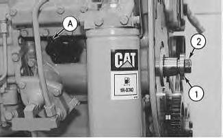
1
1. Install washer (1) and bolt (2). Ensure that the cover of the fuel pump housing is removed. Turn the fuel pump camshaft in the direction of the engine rotation until Tool (A) can be installed in the notch of the camshaft.
2. Install Tool (A) and (B) into position. Install the weight assembly for the timing advance on the fuel injection pump camshaft.
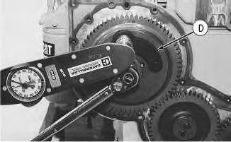
2
3. Use Tool (D) on the automatic timing advance and maintain a constant torque of 68 N·m (50 lb ft). Tighten the bolt that fastens the automatic timing advance to the fuel pump camshaft to a torque of 270 ± 25 N·m (200 ±18 lb ft).
4. Remove Tools (A), (B), (C) and (D). Install the starting motor.
End By: Install the front housing. Refer to Disassembly and Assembly, "Front Housing - Install". Copyright 1993 - 2020 Caterpillar Inc.
Thu Jan 2 16:56:50 UTC+0530 2020
PreviousScreen
Product: MOTOR GRADER
Model: 12H ES MOTOR GRADER 2GS
Configuration: 12H Motor Grader 2GS00001-UP (MACHINE) POWERED BY 3306 Engine
Disassembly and Assembly
3304B and 3306B Engines for Caterpillar Built Machines
Automatic Timing Advance - Remove
SMCS - 1272-011
Removal Procedure
Table 1
Shutdown SIS
Start By:
A. Remove the front housing. Refer to Disassembly and Assembly, "Front Housing - Remove".
NOTICE
Keep all parts clean from contaminants.
Contaminants
1. Followthe procedure in Steps3 and 4 in order to time the fuel injection pump when the front cover is removed. Follow the procedure in Steps 6 and 7 in order to time the fuel injection pump when the front cover isinstalled.
Note: The No. 1 piston should be at the top center position on the compression stroke at the start of all timing procedures.
Note: The engine is seen from the flywheel end when the direction of the crankshaft rotation is given.
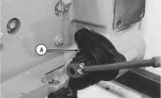
Illustration 1
2. Remove the electric starting motor and install Tool (A) .
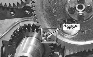
Illustration 2
3. Turn the crankshaft counterclockwise until the "C" on the crankshaft gear and the "C" on the camshaft gear are in alignment.
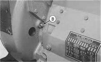
4. Remove two plugs and install Tool (B) in the flywheel housing. The large plug hole isfor viewing.
5. To find the top center compression stroke for the No. 1 piston, use Tool (A) in order to turn the flywheel clockwise for approximately 30 degrees. This procedure should be used to remove all of the end play from the timing gears.
6. Use Tool (A) in order to turn the flywheel counterclockwise in the direction of the engine rotation until Tool (B) can be installed in the flywheel. The piston is at the top center position.
Note: If you go past the bolt hole, you must start the procedure again.
Note: Remove the breather assembly from the valve mechanism cover. The piston isat the top center position on the compression stroke when the inlet valve is closed and the exhaust valve is closed for the No. 1 cylinder. You must be able to move the rocker arms up and down with your hand.
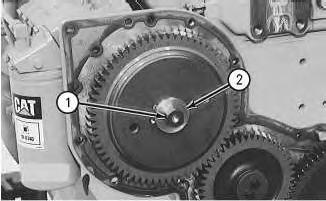
7. Remove bolt (1) and washer (2) that secures the automatic timing advance.
NOTICE
The automatic timing advance must have support during removal in order to help prevent damage to components.
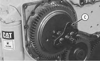
Illustration 5
g00474596
8. Install bolt (1) and leave a 6.35 mm (.250 inch) gap. Install Tool (C), as shown. Tighten the stud in order to loosen the fuel pump drive gear from the taper on the fuel injection pump camshaft.
9. Remove Tool (C) and bolt (1). Remove the automatic timing advance.
Thu Jan 2 16:55:54 UTC+0530 2020
PreviousScreen
Product: MOTOR GRADER
Model: 12H ES MOTOR GRADER 2GS
Configuration: 12H Motor Grader 2GS00001-UP (MACHINE) POWERED BY 3306 Engine
Disassembly and Assembly
3304B and 3306B Engines for Caterpillar Built Machines
Bearing Clearance - Check
SMCS - 1203-535; 1219-535
Measurement Procedure
Table 1
(Green)
Gauge (Red)
to 0.152 mm
to 0.006 inch)
Plastic Gauge (Blue)
to 0.229 mm (0.004 to 0.009 inch)
Plastic Gauge (Yellow)
to 0.020 inch)
Note: Plastic gauge may not be necessary when the engine is in the chassis.
i05977048
Keep all parts clean from contaminants.
Contaminants may cause rapid wear and shortened component life.
Note: Cat does not recommend the checking of the actual bearing clearancesparticularly on small engines. Thisisbecause of the possibility of obtaining inaccurate results and the possibility of damaging the bearing or the journal surfaces. Each Cat engine bearing is quality checked for specific wall thickness.
Note: The measurements should be within specifications and the correct bearings should be used. If the crankshaft journals and the bores for the block and the rods were measured during disassembly, no further checks are necessary. However, if the technician still wants to measure the bearing clearances, Tooling (A) is an acceptable method. Tooling (A) is less accurate on journalswith small diametersif clearancesare less than 0.10 mm (0.004 inch).
NOTICE
Lead wire, shim stock or a dial bore gauge can damage the bearing surfaces.
The technician must be very careful to use Tooling (A) correctly. The following points must be remembered:
• Ensure that the backs of the bearings and the bores are clean and dry.
• Ensure that the bearing locking tabs are properly seated in the tab grooves.
• The crankshaft must be free of oil at the contact pointsof Tooling (A).
1. Put a piece of Tooling (A) on the crown of the bearing that is in the cap.
Note: Do not allow Tooling (A) to extend over the edge of the bearing.
2. Use the correct torque-turn specifications in order to install the bearing cap. Do not use an impact wrench. Be careful not to dislodge the bearing when the cap isinstalled.
Note: Do not turn the crankshaft when Tooling (A) is installed.
3. Carefully remove the cap, but do not remove Tooling (A). Measure the width of Tooling (A) while Tooling (A) is in the bearing cap or on the crankshaft journal. Refer to Illustration 1.
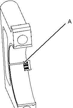

Illustration 1 g01152855
TypicalExample
4. Remove all of Tooling (A) before you install the bearing cap.
Note: When Tooling (A) is used, the readings can sometimes be unclear. For example, all parts of Tooling (A) are not the same width. Measure the major width in order to ensure that the parts are within the specification range. Refer to SpecificationsManual, "Connecting Rod Bearing Journal" and Specifications Manual, "Main Bearing Journal" for the correct clearances.
Copyright 1993 - 2020 Caterpillar Inc. All Rights Reserved. Private Network For SIS Licensees. Thu Jan 2 17:24:44 UTC+0530 2020
PreviousScreen
Product: MOTOR GRADER
Model: 12H ES MOTOR GRADER 2GS
Configuration: 12H Motor Grader 2GS00001-UP (MACHINE) POWERED BY 3306 Engine
Disassembly and Assembly
3304B and 3306B Engines for Caterpillar Built Machines Media Number -SENR5598-09
Camshaft - Remove and Install
SMCS - 1210-010
Removal Procedure
Start By:
i01037991
A. Remove the valve lifters. Refer to Disassembly and Assembly, "Lifter Group - Remove and Install".
B. Remove the timing gear cover. Refer to Disassembly and Assembly, "Front HousingRemove".
NOTICE
Keep all parts clean from contaminants.
Contaminants may cause rapid wear and shortened component life.
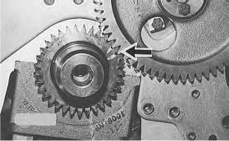
Illustration 1
g00476744
1. Turn the crankshaft to top center compression stroke for the No. 1 piston. The "C"mark on the crankshaft gear will be aligned with the "C" mark on the camshaft gear.
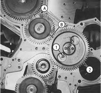
Illustration 2
g00476743
Note: Put a mark on the teeth of the fuel injection pump drive gear and the idler gear at location (A). Thiswill help to keep the engine timing correct during the removal and the installation of the camshaft. Put a mark on the teeth of the idler gear and camshaft gear (2) at location (B). When the camshaft is installed, the engine timing will be correct when the mark at location (A) isaligned with the mark at location (B) and the "C" mark on the crankshaft gear isaligned with the "C" mark on the camshaft gear.
2. Remove the bolts, the lock and washer (1) .
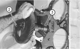
Illustration 3
NOTICE
Do not damage the lobesor the bearingswhen the camshaft is removed.
3. Carefully remove camshaft (3) from the engine.
4. If necessary, remove the bolts that hold camshaft drive gear (2) to the camshaft and remove the gear.
Installation Procedure
NOTICE
Keep all parts clean from contaminants.
Contaminants may cause rapid wear and shortened component life.
Illustration 4
1. Put camshaft drive gear (2) in position on the end of camshaft (3). Install the bolts that hold camshaft drive gear (2) to camshaft (3). Tighten the bolts to a torque of 55 ± 7 N·m (41 ± 5 lb ft).
NOTICE
Do not damage the lobesor the bearingswhen the camshaft is installed.
2. Put 8T-2998 Camshaft Lubricant on the camshaft lobes only and put clean engine oil on the bearing journals.
Note: During the installation of camshaft (3), rotate the camshaft in both directions in order to prevent binding in the camshaft bearing bores.
3. Carefully install camshaft (3) into the engine.
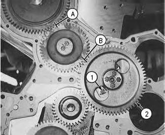
Illustration 5
Illustration 6
4. Make sure that the mark on the teeth of the fuel injection pump drive gear and the idler gear are in alignment at location (A). Make sure that the mark on the teeth of the idler gear and camshaft gear (2) are in alignment at location (B). Align the "C" markson the crankshaft gear and camshaft gear (2). When all of the timing marksare in alignment the engine timing is correct.
5. Install washer (1), the lock and the two bolts that hold the camshaft in position in the engine.
End By:
a. Install the valve lifters. Refer to Disassembly and Assembly, "Lifter Group - Remove and Install".
b. Install the timing gear cover. Refer to Disassembly and Assembly, "Front Housing - Install".
PreviousScreen
Product: MOTOR GRADER
Model: 12H ES MOTOR GRADER 2GS
Configuration: 12H Motor Grader 2GS00001-UP (MACHINE) POWERED BY 3306 Engine
Disassembly and Assembly
3304B and 3306B Engines for Caterpillar Built Machines
Camshaft Bearings - Remove and Install
SMCS - 1211-010
Removal Procedure Table 1
Start By:
A. Remove the Flywheel Housing. Refer to Disassembly and Assembly, "Flywheel HousingRemove and Install".
B. Remove the Oil Pan Plate. Refer to Disassembly and Assembly, "Oil Pan Plate - Remove and Install".
C. Remove the Camshaft. Refer to Disassembly and Assembly, "Camshaft - Remove and Install".
NOTICE
Keep all parts clean from contaminants. Contaminants may cause rapid wear and shortened component life.
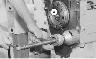
Illustration 1 g00478567
1. Use Tool (A) to remove the camshaft bearing from the cylinder block. Start with the front bearings and work to the rear bearing.
Installation Procedure
Table 2
Tools
NOTICE
Keep all parts clean from contaminants.
Contaminants may cause rapid wear and shortened component life.
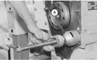
Illustration 2
1. Use Tool (A) to install the camshaft bearings in the 3304B and 3306B cylinder block.
Note: The camshaft bearings in the 3304B have pressure lubrication. The intermediate camshaft bearingsand the rear camshaft bearings in the 3306B have splash lubrication.
2. Install the camshaft bearings in the 3304B cylinder block, as follows:
(a) Install the front bearing to a depth of 0.57 ± 0.5 mm (0.022 ± 0.02 inch). Ensure that the oil holes are in a horizontal position and that the camshaft bearing joint is at the top of the engine. The camshaft bearing joint can not be more than 15° degreesfrom vertical in either direction.
(b) Install the center bearing to a depth of 303.2 ±0.5 mm (11.94 ± 0.02 inch). Ensure that the oil holesin the camshaft bearing are in alignment with the oil holes in the cylinder block.
(c) Install the rear bearing to a depth of 604.9 ± 0.5 mm (23.81 ±0.02 inch). Ensure that the oil holes in the camshaft bearing are in alignment with the oil holes in the cylinder block.
This is the sample of the manual Click on the download link for complete manual
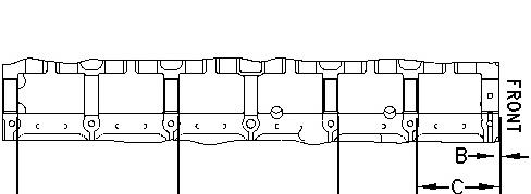
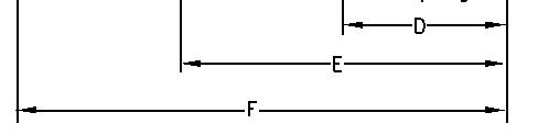
Illustration 3 g00478822
1. Install the camshaft bearings in the 3306B cylinder block, as follows:
2. Install front bearing (B) to a depth of 0.5 ± 0.5 mm (.02 ± .02 inch). Ensure that the oil holesare in a horizontal position and that the camshaft bearing joint is at the top of the engine. The camshaft bearing joint cannot be more than 15 degrees from the vertical position in either direction.
3. Install the remainder of the bearings. Install the bearingsto the dimensions that are given from the front face of the cylinder block: (C) 154.0 ± 0.5 mm (6.06 ±.02 inch), (D) 303.2 ±0.5 mm (11.94 ± .02 inch), (E) 601.7 ± 0.5 mm (23.69 ± .02 inch) and (F)903.4 ± 0.5 mm (35.57 ±.02 inch).
End By:
a. Install the camshaft. Refer to Disassembly and Assembly, "Camshaft - Remove and Install".
b. Install the oil pan plate. Refer to Disassembly and Assembly, "Engine Oil Pan Plate - Remove and Install".
c. Install the flywheel housing. Refer to Disassembly and Assembly, "Flywheel HousingRemove and Install".
Copyright 1993 - 2020 Caterpillar Inc. All Rights Reserved. Private Network For SIS Licensees. Thu Jan 2 17:19:17 UTC+0530 2020