

Previous Screen
Product: MOTOR GRADER
Model: 120M 2 MOTOR GRADER M9C
Configuration: 120M Series 2 Motor Grader
Disassembly and Assembly
120M Series 2 and 120M2 Motor Graders Machine Systems
Disconnecting Snap To Connect Fittings
SMCS - 7554-X6
Disconnection Procedure
Engine
Personal injury can result from removing hoses or fittings in a pressure system.
Failure to relieve pressure can cause personal injury.
Do not disconnect or remove hoses or fittings until all pressure in the system has been relieved.
NOTICE
Using the incorrect size snap to connect (STC) wrench can cause slippage, resulting in personal injury. Always verify that the STC wrench size matches the size fitting to be disconnected.
1. Lower all work tools and attachments to the ground.
2. Release the system pressure. Refer to Disassembly and Assembly, "System PressureRelease".
3. Clean the connection that is to be disassembled. Clean the surrounding area to ensure that the connection is free of all dirt, dust, and grit.
4. Pressure can be trapped in circuits after the engine has stopped. Personal injury or death can result if all pressures are not released. Ensure that the pressure is zero in the line that is being disconnected.
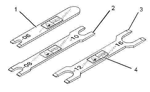
5. Select the designated release tool for the size of the connection. Using the wrong tool may result in damage to the coupling, or cause slippage, resulting in unsafe conditions.
Note: Prying on the connection may result in damage to the release sleeve, requiring hose replacement.
6. Insert the release tool behind the release sleeve, so that the release tool is perpendicular to the connection. Fully insert the release tool to cause the release sleeve to move and separate the retaining ring. The coupling may now be separated.
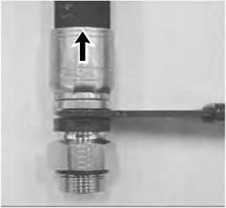
7. Pull on the hose in the direction parallel to the axis of connection while keeping the release tool engaged. Pulling the hose at an angle may result in extra force required to disconnect the connection.
8. Cover both ends of the connection with recommended plugs or caps to avoid contamination.
Connection Procedure
1. Clean the connection that is to be assembled. Ensure that the connection is free of all dirt, dust, and grit.
Illustration 3
g02141956
Note: If the release sleeve is damaged during the connection or disconnection of the STC connection, the male portion must be replaced with new parts.
Note: Do not use the rubber sleeve as leverage to push the male half into the female half of the STC connection.
2. Align the STC fitting on the hose assembly with the STC connector. Push the hose fitting into the mating connector until you feel a definite snap and a solid stop.
3. Pull straight back on the connection. An improperly made connection will disconnect.
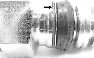
Illustration 4
Red ring, on an improper connection.
g02141958
4. Check for a visible red ring. An improper assembly shows the red ring.
Note: For more information on the operation and the maintenance of Snap to Connect wrenches, refer to Tool Operating Manual, NEHS1083.
Copyright 1993 - 2025 Caterpillar Inc. All Rights Reserved. Private Network For SIS Licensees. Tue May 13 01:15:55 UTC+0530 2025
Previous Screen
Product: MOTOR GRADER
Model: 120M 2 MOTOR GRADER M9C
Configuration: 120M Series 2 Motor Grader M9C00001-UP (MACHINE) POWERED BY C7.1 Engine
Disassembly and Assembly
120M Series 2 and 120M2 Motor Graders Machine Systems
Media Number -KENR9465-03 Publication Date -01/04/2015 Date Updated -08/04/2015
Battery - Remove and Install
SMCS - 1401-010
Removal Procedure
Personal injury can result from failure to disconnect the battery.
First, disconnect the negative battery cable. Then, disconnect the positive battery cable.
A positive power lead can cause sparks if the battery is not disconnected. Sparks can possibly result in battery explosion or fire.
1. Turn the key for the battery disconnect switch to the OFF position. Remove the key.
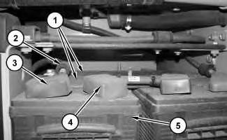
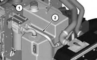
2. Remove hold-downs (1). Remove clip (2). Disconnect cable assemblies (3) and (4). Use two people in order to remove battery (5). The weight of battery (5) is approximately 54 kg (120 lb).
2
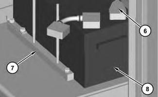
3. Disconnect cable assembly (6). Remove block (7). Use two people in order to remove battery (8). The weight of battery (8) is approximately 54 kg (120 lb).
Installation Procedure
1. Install batteries (5) and (8) in the reverse order as the removal.
Previous Screen
Product: MOTOR GRADER
Model: 120M 2 MOTOR GRADER M9C
Configuration: 120M Series 2 Motor Grader M9C00001-UP (MACHINE) POWERED BY C7.1 Engine
Disassembly and Assembly
120M Series 2 and 120M2 Motor Graders Machine Systems
Media Number -KENR9465-03 Publication Date -01/04/2015 Date Updated -08/04/2015
Duo-Cone Conventional Seals - Install
SMCS - 7561-012-SA; 7561-012; 7561-016
Assembly and Installation of Conventional Duo-Cone Seals
This instruction provides the procedure for assembling and installing conventional Duo-Cone Seals.
When the Duo-Cone Seals are installed and assembled, you must use the correct procedures. The Duo-Cone Seal may fail from one or more mistakes that are made during assembly or during installation of the seal components.
Reference: Special Instruction, SEHS8484, "Tool and Specification Chart for Conventional DuoCone Seals"
Required Tools
Use the tools in Table 1 in order to correctly measure the spacing of the Duo-Cone Seals after the seals are installed.
Table 1
Required Tools Item Part
10 6V-3075 Dial Indicator 1
11 6V-6167 Contact Point 1
12 3P-1565 Collet Assembly 1
13 165-8958 Dial Indicator Base 1
Correct Assembly of Conventional Duo-Cone Seals
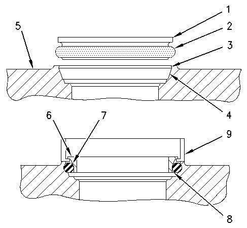
Illustration 1 g00446486
(1) Seal ring
(2) Rubber toric ring
(3) Housing retaining lip
(4) Housing ramp
(5) Seal ring housing
(6) Seal ring face
(7) Seal ring ramp
(8) Seal ring retaining lip
(9) Installation tool
Assembly and Installation Procedure
Avoid prolonged skin contact with isopropyl alcohol. Avoid breathing the vapors in enclosed areas without adequate ventilation and do not smoke.
Isopropyl alcohol is flammable. Do not use near open flame, welding operations, or around heated surfaces exceeding 482°C (900°F).
This is the sample of the manual
Click on the download link for complete Manual
1. Remove any film, dust or other foreign matter from the following components:
◦ Rubber toric ring (2)
◦ Housing ramp (4)
◦ Seal ring ramp (7)
◦ Housing retaining lip (3)
◦ Seal ring retaining lip (8)
◦ Seal ring housing (5)
Note: Seal rings have very sharp edges. Protective gloves should be worn in order to prevent injury.
Use isopropyl alcohol or other approved cleaning agents. Use a clean lint free cloth for wiping. All components should be completely dry before proceeding.
Note: Never permit oil to contact rubber toric ring (2), housing ramp (4) or seal ring ramp (7) before both seal rings (1) are assembled in the final position.
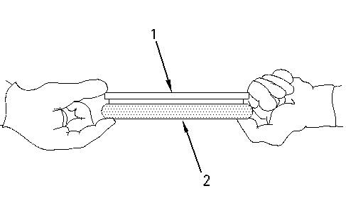
Illustration 2 g00534617
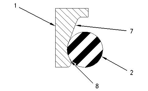
Illustration 3 g00446488
2. Put rubber toric ring (2) on seal ring (1). Make sure that the rubber toric ring is positioned at the bottom of seal ring ramp (7). The rubber toric ring must rest against retaining lip (8). The rubber toric ring must be straight in the seal ring. The rubber toric ring must not be twisted.
Note: Be careful when you are working on the rubber toric ring. Nicks, cuts or scratches may cause leaks.
3. Refer to Special Instruction, SEHS8484, "Tool and Specification Chart for Conventional Duo-Cone Seals" in order to select the proper installation tool.
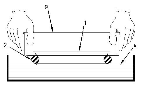
Illustration 4 g00534621 Use towels or a mat (A) that is made of foam in order to aid in the installation of toric ring (2).
4. Use Tooling (9) to install rubber toric ring (2) on seal ring (1). Lightly dampen the lower half of rubber toric ring (2) with an appropriate lubricant. Refer to the "Acceptable Lubricants for Assembly" in this publication for additional information. Use the following procedure in order to dampen the rubber toric ring:
◦ Wipe the seal with a lint free cloth.
◦ Place towels or a mat that is made of foam at the bottom of a container. Soak the towels or the mat with the lubricant. Dip the rubber toric seal in the container.
Note: Periodically inspect the installation tool for damage. If necessary, replace the installation tool .
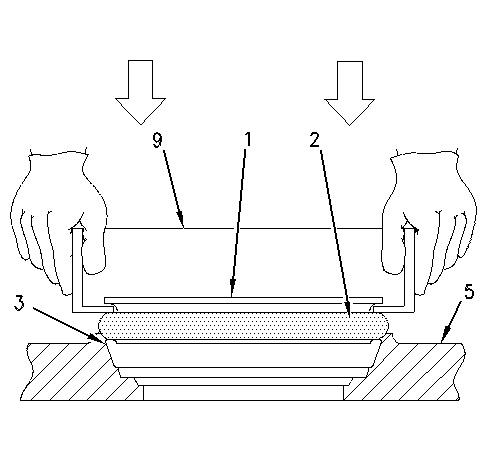
Illustration 5
g00534622
5. Make sure that the lower half of rubber toric ring (2) is still wet. Use Tooling (9) in order to position seal ring (1) and rubber toric ring (2) squarely against seal ring housing (5). Make sure that you use sudden pressure and even pressure when you press a toric ring that has a small diameter. Press rubber toric ring (2) under housing retaining lip (3) that is part of seal ring housing (5). Use the following procedure in order to install a rubber toric ring that has a large diameter:
◦ Push the rubber toric ring over the seal ring retaining lip on one side.
◦ Tap the installation tool with a rubber mallet on the opposite side of the rubber toric ring. Tap until the rubber toric ring is past the seal ring retaining lip of the housing.
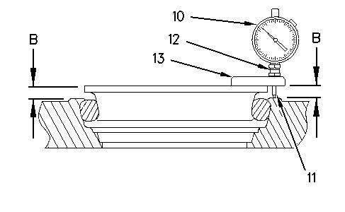
Illustration 6 g00534720 (B) Assembled height (10) Dial indicator (11) Contact point (12) Collet assembly (13) Dial indicator base (plastic)
6. Check assembled height (B) at four locations that are 90 degrees from each other. Use a calibrated 6V-3075 Dial Indicator and the related tools in Table 1 in order to measure the assembled height. The difference in height must not exceed 1.0 mm (0.04 inch). Refer to Illustration 6.
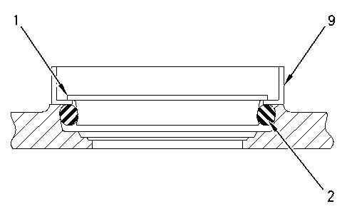
Illustration 7 g00446492
7. Do not adjust the seal ring (1) by pushing on the seal ring or by pulling on the seal ring. Use Tooling (9) in order to push down on the seal.
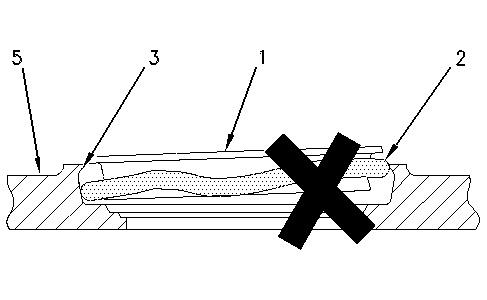
Illustration 8 g00446493
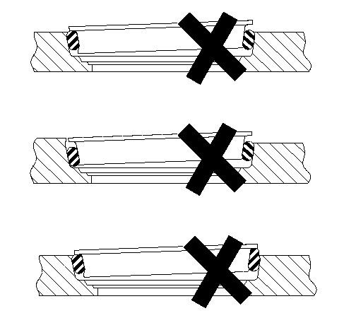
Illustration 9 g00446494
Examples of incorrect assembly
8. Rubber toric ring (2) may twist during installation if the seal is not completely wet or if there are burrs or fins on housing retaining lip (3) that is part of seal ring housing (5). Misalignments, twists and bulges of the rubber toric ring will cause Duo-Cone Seal failures. If correct installation is not obvious, remove the toric ring from the housing and repeat the installation procedure.
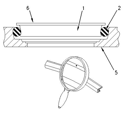
Illustration 10 g00446495
9. Wipe seal ring face (6) that is part of seal rings (1) by using a lint free cloth. No particles of any kind are permissible on the sealing surfaces. A small piece of paper from a paper towel can force apart the seal ring face, which will cause a leak.
Note: Rubber toric ring (2) must never slip on the ramps of seal ring (1) or the ramps of seal ring housing (5). In order to prevent slippage, allow adequate time for evaporation of the lubricant before proceeding with the procedure. Once the rubber toric ring is correctly positioned, the rubber toric ring must roll only on the ramps.
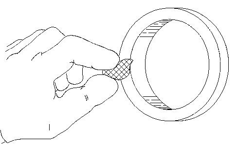
Illustration 11 g00534623
10. Apply a thin film of clean oil on the entire seal ring face of one or both seals. Use a lint free cloth or brush in order to distribute the oil evenly. Be careful not to get any oil on the rubber toric rings. Lubricate the seal faces by using the same oil that was used during assembly. Dye may have been used in the oil that was used during assembly. Use the same kind of oil without dye in order to lubricate the seal faces.
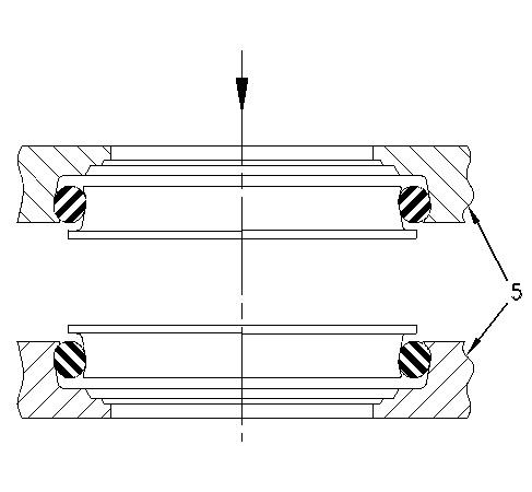
11. Make sure that both seal ring housings (5) are in correct alignment and that the seal ring housings are concentric. Move the parts slowly and move the parts carefully toward each other.
Note: Do not force the seal ring and the seal ring housing together in a sudden manner. The seal component could be scratched or the seal component could be broken if the components are slammed together.
12. Tighten the bolts after the components are in the correct position.
Acceptable Lubricants for Assembly
Avoid prolonged skin contact with isopropyl alcohol. Avoid breathing the vapors in enclosed areas without adequate ventilation and do not smoke.
Isopropyl alcohol is flammable. Do not use near open flame, welding operations, or around heated surfaces exceeding 482°C (900°F).
Note: Do not use any liquid that leaves an oil film. Do not use any liquid that does not evaporate quickly. All of the guidelines for safety and all of the guidelines for disposal must be followed when you use a flammable liquid. The following liquids are acceptable lubricants for assembly:
• Quaker Solvo Clean 68-0
• Houghto-Grind 60 CT
• Isopropyl alcohol
Some seal kits come with silicone toric rings. Silicone toric rings can be chilled for easier installation. This will allow the toric ring to contract for easier installation.
Seals should be placed in a freezer for 5 minutes. Temperature in the freezer should be between −40°C (−40°F) to −18°C (0°F). Chilling should be done prior to installation. Contraction will be sufficient to allow installation. The seals should be allowed to warm to room temperature prior to further assembly.
Result of Incorrect Assembly
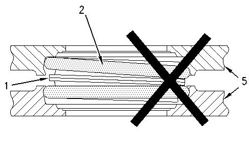
13 g00446498
The slipping of the rubber toric ring on the housing ramp or on the seal ring ramp may result in uneven pressure on the seal face. Uneven pressure on the seal face causes galling, scoring, and leakage.
If the rubber toric ring slips at one location but not all the way around the seal ring, the toric ring will twist.
The twisted toric ring could be cocked. Seals that are cocked will cause uneven pressure on the seal face. Seals that are cocked may also cause possible galling, scoring, and leakage.
The twisted toric ring could oscillate when the ring is rotated. Seals that oscillate may allow dirt into the seal joint. This is caused by the pumping action that is created by the toric ring that is oscillating.
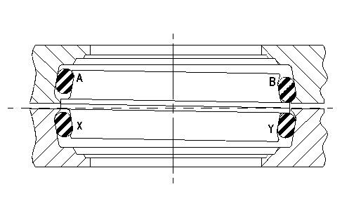
Illustration 14 g00446499
Illustration 14 shows a toric ring that is assembled incorrectly. The upper housing is stationary. The lower housing is rotating.
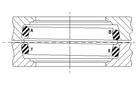
Illustration 15 g00446500
Illustration 15 shows the same seal after the lower housing has rotated 180 degrees. In this position, there will be high pressure at point (B) and at point (X). These points of high pressure may result in galling of the toric rings. There will be low pressure at point (A) and at point (Y) which will result in possible leakage.
Previous Screen
Product: MOTOR GRADER
Model: 120M 2 MOTOR GRADER M9C
Configuration: 120M Series 2 Motor Grader M9C00001-UP (MACHINE) POWERED BY C7.1 Engine
Disassembly and Assembly
120M Series 2 and 120M2 Motor Graders Machine Systems
Media Number -KENR9465-03 Publication Date -01/04/2015 Date Updated -08/04/2015
Hydraulic Tank and Filter - Remove
SMCS - 5056-011
Removal Procedure
Start By:
A. Remove the engine enclosure. Refer to Disassembly and Assembly, "Engine EnclosureRemove".
NOTICE
Care must be taken to ensure that fluids are contained during performance of inspection, maintenance, testing, adjusting and repair of the product. Be prepared to collect the fluid with suitable containers before opening any compartment or disassembling any component containing fluids.
Refer to Special Publication, NENG2500, "Caterpillar Dealer Service Tool Catalog" for tools and supplies suitable to collect and contain fluids on Caterpillar products.
Dispose of all fluids according to local regulations and mandates.
Personal injury can result from hydraulic oil pressure and hot oil.
Hydraulic oil pressure can remain in the hydraulic system after the engine has been stopped. Serious injury can be caused if this pressure is not released before any service is done on the hydraulic system.
Make sure all of the work tools have been lowered to the ground, and the oil is cool before removing any components or lines. Remove the oil filler cap only when the engine is stopped, and the filler cap is cool enough to touch with your bare hand.
NOTICE
Keep all parts clean from contaminants.
Contaminants may cause rapid wear and shortened component life.
Note: Put identification marks on all hoses, on all hose assemblies, on all harness assemblies, and on all tube assemblies for installation purposes. Plug all hose assemblies and all tube assemblies. This helps to prevent fluid loss, and this helps to keep contaminants from entering the system.
1. Release the system pressure. Refer to Operation and Maintenance Manual, "System Pressure - Release".
2. Drain the hydraulic system into a suitable container for storage or disposal. Refer to Operation and Maintenance Manual, "Capacities - Refill". Refer to Operation and Maintenance Manual, "Hydraulic System Oil - Change". Illustration 1
3. Disconnect hose (1). Remove tube assembly (2) .
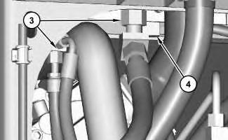
Illustration 2
4. Disconnect fittings (3) .
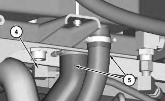
Illustration 3
g01366540
5. Disconnect fitting (4). Disconnect hoses (5) .
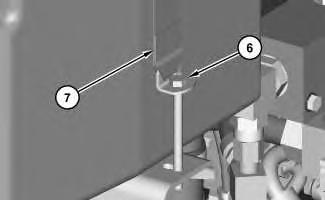
Illustration 4
g01366546
6. Remove bolt (6). Position strap (7) out of the way.
This is the sample of the manual
Click on the download link for complete Manual
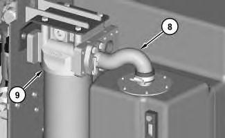
Illustration 5
g01366548
7. Remove tube assembly (8). Remove hydraulic oil filter assembly (9) .
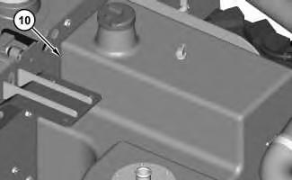
Illustration 6
8. Remove hydraulic oil tank (10) .
g01366555
Copyright 1993 - 2025 Caterpillar Inc. All Rights Reserved. Private Network For SIS Licensees. Tue May 13 01:16:34 UTC+0530 2025