

Previous Screen
Product: MOTOR GRADER
Model: 120K 2 MOTOR GRADER SZZ
Configuration: OEM SOLUTIONS GROUP PRODUCT COMMONALITY CHART SZZ00001-UP (MACHINE)
Troubleshooting
120K, 120K Series 2, 12K, 140K, 140K Series 2 and 160K Motor Graders Power Train Electronic Control System
Media Number -UENR3994-03 Publication Date -01/10/2014 Date Updated -30/08/2017
Symptom Troubleshooting
SMCS - 7000-035
Use the following guidelines when troubleshooting a symptom.
Know the Machine
i05895988
Understand the operation of the machine. Know if the symptom is a characteristic of normal operation or if the symptom is a failure.
Read the Systems Operation information to understand the systems of the machine. Understand the interaction of the machine systems.
Understand the Symptom
Speak with the operator about the symptom. Inspect the machine and look for problems. Notice any unusual odors in the air. Listen for unusual noises. Acquire the following Information:
• The performance of the machine prior to the failure
• First occurrence of the symptom
• The operating conditions at the time of the failure
• The sequence of events prior to the failure (order of the occurrences)
• The troubleshooting steps that have been taken
• The history of repairs of the machine
• The preventive maintenance of the machine
• Related service information about current problems that affect the serial number of the machine
Perform the "Visual Inspection" steps.
Verify the Symptom
When possible, attempt to duplicate the symptom. Operate the machine and repeat the conditions that caused the failure. Check the gauges inside the cab. Notice any unusual odors in the air. Listen for unusual noises.
Determine if the ECM has detected any faults. A diagnostic code is used to specify each detected fault.
Determine Possible Causes
Use the information from the operator and your inspection. Attempt to identify a common cause if there is more than one symptom.
If the problem is not resolved after troubleshooting the diagnostic codes, continue troubleshooting using the "Symptom Troubleshooting" section of this manual. Identify the component that is the most probable cause of the symptom.
Test and Repair the System
Use the tests and procedures in this manual to verify the cause of the symptom. Once the cause has been identified, repair the failure. Test the system again to verify that the symptom is resolved.
Provide Feedback to Caterpillar
Share your troubleshooting information with Caterpillar. Use the form in "SIS" or "CBT" feedback to write a brief description about the symptom, testing, and repair. Include your phone number or e-mail address so that you can be contacted. This feedback information helps Caterpillar improve service information. Copyright 1993 - 2025 Caterpillar Inc.
Rights Reserved.
Network For SIS Licensees. Tue May 13 01:12:40 UTC+0530 2025
Previous Screen
Product: MOTOR GRADER
Model: 120K 2 MOTOR GRADER SZZ
Configuration: OEM SOLUTIONS GROUP PRODUCT COMMONALITY CHART SZZ00001-UP (MACHINE)
Troubleshooting
120K, 120K Series 2, 12K, 140K, 140K Series 2 and 160K Motor Graders Power Train Electronic Control System
Media Number -UENR3994-03
Event Code List
SMCS - 4800
Date -01/10/2014
Updated -30/08/2017
i07104215
Event codes alert the operator or the technician that an abnormal operating condition exists in one of the machine systems.
When the "Transmission ECM" activates an event code, the operator or the technician will be alerted by the Messenger. Most active events will be logged by the ECM. Some events are active only. Active only events are not logged. The events that are active and the events that are logged can be viewed with the following equipment:
• Messenger
• Cat® Electronic Technician (Cat ET)
Warning Levels
The ECM will assign a warning level to an active event code. Event codes are one of three levels. The level is according to the severity of the abnormal condition. Each warning level requires a specific response from the operator. The warning levels and the required operator response are listed below.
Warning Level 1
Warning level 1 alerts the operator that a machine system requires attention. The operator should check that the involved system condition or the operator should perform maintenance on the involved system at the earliest possible time.
Warning Level 2
Warning level 2 requires changing the operation of the machine or performing a maintenance procedure. System components may be damaged if the cause of this warning is ignored.
Warning Level 3
Warning level 3 requires an immediate safe shutdown of the machine. An immediate shutdown is required to avoid damage to the machine or injury to personnel around the machine. The problem that caused the event must be corrected before machine operation can resume.
Indications and System Response
Gauge Cluster Indicators
The Gauge Cluster Indicators alert the operator when an event code is active. Event codes are activated in one of three warning levels according to the severity of the condition.
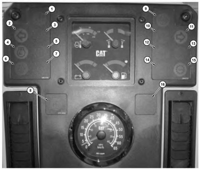
Illustration 1 g03371058
Indicators that are on the instrument cluster
(1) Action Indicator
(2) Left Hand Turn Indicator
(3) High Beam Indicator
(4) Throttle Lock Indicator
(5) Check Engine Indicator
(6) Low Engine Oil Pressure Indicator
(7) Check Transmission Indicator
(8) Accugrade Fault Indicator
(9) Differential Lock Indicator
(10) Centershift Pin Indicator
(11) Right Hand Turn Indicator
(12) Brake Air Pressure Indicator
(13) Transmission Filter Bypass Indicator
(14) Parking Brake Engaged Indicator
(15) Autoshift Indicator Lamp
(16) Blank (Not Used)
The warning indicators for the subsystem on the Instrument Cluster will illuminate when an EID is activated for a particular subsystem. When level 1 events are active, the warning indicator for the subsystem will be the only type of indicator that will illuminate.
The action Indicator will flash red when a level 2 warning or level 3 warning is active. If communication between Messenger and the Instrument Cluster fails, the action lamp will flash yellow.
The action alarm is driven as an output directly from the Instrument Cluster. If a level 3 warning is active, the action alarm will sound a tone that is pulsing. The action alarm will sound these tones to alert the machine operator that immediate action is required.
If two warnings of a different level are active at the same time, the highest level warning will be displayed.
The response of the Messenger to these warning levels is shown in the following table.
Table 1
OPERATION
Action Indicator Sounds Of The Action Alarm 1 ON OFF OFF No immediate action is required. The system needs attention soon.
Action That Is Required By The Operator Possible Result (1)
No harmful effects or damaging effects 2 ON Flash ON and OFF. OFF Change machine operation or perform maintenance to the system.
3 ON Flash ON and OFF Pulse ON and OFF Immediately perform a safe engine shutdown.
(1) Possible result if no action is taken by the operator.
Cat Electronic Technician (Cat ET) Service Tool
Damage to system components
Injury to operator or severe damage to components
When an abnormal operating condition of the "transmission" occurs, the status screen on the Cat ET indicates that there is an active event.
Event codes are displayed on the Cat ET service tool in the following format:
EXXXX Description of the code
The "E" means that the code is an event code. The "XXXX" is a numeric identifier. The numeric identifier is followed by a description of the code.
Active event codes are listed in ascending numerical order. The code with the lowest number is listed first. Once a logged code is inactive, the code will be displayed with the letters “IN” for inactive. An event code that is not recorded will be removed when the event code is no longer active.
Logged Event Codes
Some event codes are logged in the ECM memory. Some event codes are active only. The logged event codes are listed in numerical order.
A logged code is cleared from memory when one of the following conditions occur:
• The service technician manually clears the code.
• The code does not reoccur for 1000 hours.
• A new code is logged and there are already 20 logged codes in memory. In this case, the oldest logged code is cleared.
Note: Always clear logged event codes after investigating and correcting the problem which generated the code.
Troubleshooting
Perform the following steps to troubleshoot an event:
1. Obtain the following information from the operator:
◦ The event and the time of the event
◦ Determine the operating conditions of the engine at the time of the event. Conditions such as engine rpm and load may be important.
◦ Determine if there are any systems that were installed by the dealer or by the customer that could cause the event.
2. Verify that the event is not due to normal machine operation. Verify that the event is not due to error of the operator.
3. Check all fluid levels and all oil levels.
4. Troubleshoot and repair any active diagnostic codes.
List of Event Codes For the Transmission ECM
The following table lists the event codes that apply to the control system of the "powertrain". The recommended response is listed. Use the Cat ET service tool to determine the event codes that are active or logged.
This is the sample of the manual
Click on the download link for complete Manual
List of Event Codes (EID) For the Transmission ECM
EID Level Description
0049 2 Coasting in Neutral
0329 2 Transmission Filter plugged
0627 2 Parking Brake abuse
Possible Cause and Recommended Response
Transmission abuse. Apply the brake to stop the machine. Set parking brake after machine comes to a full stop.
This code is active and recorded when the temperature of the transmission oil is above 50° C (122° F) and the bypass switch for the Transmission Oil Filter is set to the bypass mode.
The code is deactivated by cycling power to the machine by turning OFF and ON key start switch and/or the disconnect switch. If the code is still present, then replace the transmission oil filter.
Caused by driving the machine with the parking brake ON. E627 will occur if the machine is traveling at a speed that is greater than 8 km/h (5 mph) and the parking brake switch is toggled to the ON position.
0737 2 Inching Pedal disabled due to system fault Active when both CID 0573 and CID 1484 are faulted.
The ECM internal clock is too far out of alignment with the other control module clocks on the machine.
0861 1 Clock manual alignment required
0877 2 High Transmission Oil Temperature
Use the Cat ET service tool tomanually align the clock with the other control modules.
Activation/De-activation points are not dependent on the speed of the machine.
Activated when transmission oil temperature reaches 115° C (239° F) for 300 seconds or 120° C (248° F) for 15 seconds. Resets when oil temperature decreases to less than 107° C (224° F).
Check transmission oil level.
Modify machine operation to reduce system load.
Triggered if the internal transmission shaft speed exceeds the specified threshold RPM for a certain gear.
1293 1 Transmission Internal Component Overspeed
1293 2 Transmission Internal Component Overspeed
Probable Cause: Inching pedal is engaged and machine coasting on grades
Modify machine operation to prevent coasting conditions.
Triggered if the internal transmission shaft speed exceeds the specified threshold RPM for a certain gear by a specified speed greater than what triggered the Level 1 code.
Copyright 1993 - 2025 Caterpillar Inc. All Rights Reserved. Private Network For SIS Licensees.
Probable Cause: Inching pedal is engaged and machine coasting on grades
Modify machine operation to prevent coasting conditions.
Tue May 13 01:12:58 UTC+0530 2025
Previous Screen
Product: MOTOR GRADER
Model: 120K 2 MOTOR GRADER SZZ
Configuration: OEM SOLUTIONS GROUP PRODUCT COMMONALITY CHART SZZ00001-UP (MACHINE)
Troubleshooting
120K, 120K Series 2, 12K, 140K, 140K Series 2 and 160K Motor Graders Power Train Electronic Control System
Media Number -UENR3994-03 Publication Date -01/10/2014 Date Updated -30/08/2017
Diagnostic Code List
SMCS - 7569
i05296343
Use the Messenger or the Caterpillar Electronic Technician (Cat ET) service tool in order to view the active diagnostic codes for the transmission/chassis ECM. Perform the procedure that corresponds to the Module Identifier (MID), the Component Identifier (CID) and the Failure Mode Identifier (FMI) of the diagnostic code.
Module Identifier (MID)
The module identifier (MID) identifies the electronic control module that activated the diagnostic code. Each electronic control module on the machine has a unique MID. Use the following chart to match the MID for each diagnostic code to a specific electronic control module. The chart for the Module Identifier (MID) is located on the electrical schematic for your machine. See the chart if the MID is not shown on the display of your machine.
Table 1
Module Identifiers
MID Description 81 Transmission ECM
Component Identifier (CID)
Each component has a component identifier (CID). The ECM will activate the CID diagnostic code for a particular component when a problem in the circuit is detected.
All the CID codes that can be activated by the transmission/chassis ECM are shown in Table 2.
Table 2
Diagnostic Code List of the Transmission/Chassis ECM (MID 81)(1)
CID 0041 - 8 VDC Sensor Supply
FMI 03 Voltage above normal
FMI 04 Voltage below normal
CID 0168 - Electrical System Voltage
FMI 00 Data valid but above normal operating range
FMI 01 Voltage below normal
FMI 02 Data erratic, intermittent, or incorrect
CID 0177 - Transmission Oil Temperature Sensor
FMI 03 Voltage above normal
FMI 04 Voltage below normal
CID 0191 - Transmission Output Speed Sensor
FMI 02 Data erratic, intermittent, or incorrect
CID 0247 - SAE J1939 Data Link
FMI 09 Abnormal update
FMI 14 Special instruction
CID 0248 - Cat Data Link
FMI 09 Abnormal update
FMI 14 Special Instruction
CID 0444 - Starter Motor Relay
FMI 03 Voltage above normal
FMI 05 Current below normal
FMI 06 Current above normal
CID 0573 - Inching Pedal Position Sensor
FMI 03 Voltage above normal
FMI 04 Voltage below normal
FMI 08 Abnormal frequency, pulse width, or period
CID 0590 - Engine ECM
FMI 09 Abnormal update
FMI 14 Special instruction
CID 0637 - Backup Alarm
FMI 06 Current above normal
CID 0668 - Transmission Control (Shift Lever)
FMI 02 Data Erratic, Intermittent, or Incorrect
FMI 03 Voltage above normal
CID 0669 - Transmission Input Speed Sensor
FMI 02 Incorrect, intermittent, erratic data
CID 0674 - Transmission Intermediate Speed Sensor 1
FMI 02 Incorrect, intermittent, erratic data
CID 0675 - Transmission Intermediate Speed Sensor 2
FMI 02 Incorrect, intermittent, erratic data
CID 1326 - Location Code
FMI 02 Incorrect, intermittent, erratic data
CID 1401 - Transmission Clutch Solenoid 1
FMI 03 Voltage above normal
FMI 05 Current below normal
FMI 06 Current above normal
FMI 13 Out of calibration
CID 1402 - Transmission Clutch Solenoid 2
FMI 03 Voltage above normal
FMI 05 Current below normal
FMI 06 Current above normal
FMI 13 Out of calibration
CID 1403 - Transmission Clutch Solenoid 3
FMI 03 Voltage above normal
FMI 05 Current below normal
FMI 06 Current above normal
FMI 13 Out of calibration
CID 1404 - Transmission Clutch Solenoid 4
FMI 03 Voltage above normal
FMI 05 Current below normal
FMI 06 Current above normal
FMI 13 Out of calibration
CID 1405 - Transmission Clutch Solenoid 5
FMI 03 Voltage above normal
FMI 05 Current below normal
FMI 06 Current above normal
FMI 13 Out of calibration
CID 1406 - Transmission Clutch Solenoid 6
FMI 03 Voltage above normal
FMI 05 Current below normal
FMI 06 Current above normal
FMI 13 Out of calibration
CID 1407 - Transmission Clutch Solenoid 7
FMI 03 Voltage above normal
FMI 05 Current below normal
FMI 06 Current above normal
FMI 13 Out of calibration
CID 1408 - Transmission Clutch Solenoid 8
FMI 03 Voltage above normal
FMI 05 Current below normal
FMI 06 Current above normal
FMI 13 Out of calibration
CID 1484 Inching Pedal Switch
FMI 03 Voltage above normal
FMI 04 Voltage below normal
CID 1580 - Powertrain Filter Bypass Lamp
FMI 03 Voltage above normal
FMI 05 Current below normal
CID 2671 - Air Conditioning Compressor Solenoid
FMI 03 Voltage above normal
FMI 05 Current below normal
FMI 06 Current above normal
(1) This table is only for MID 81 diagnostic codes that can be activated by the Transmission ECM.