

Previous Screen
Product: MOTOR GRADER
Model: 120H NA MOTOR GRADER 6YN
Configuration: 120H Series NA Motor Grader 6YN00001-UP (MACHINE) POWERED BY 3116 Engine
Troubleshooting
120H, 12H, 135H, 140H, 143H, 160H and 163H Motor Graders Hydraulic and Steering System
Media Number -SENR9186-09 Publication Date -01/09/2014
Hydraulic and Steering System
SMCS - 4300-035; 5050-035
Implement System
Problem: The ripper cylinders are failing prematurely.
Probable Cause
i02757321
• The ripper lines are installed incorrectly. The installation causes the relief valve to be bypassed. The bypass exposes the cylinders to pressure surges. The new hoses and fittings prevent the hoses from being installed incorrectly.
Problem: When you steer the machine, the implement slows down or the implement stops.
Probable Cause
• The low standby pressure of the hydraulic and steering pump is set low. Refer to the Testing and Adjusting, "Pump Control Valve (Hydaulic, Steering) - Test and Adjust" section in this manual.
• The steering priority valve has failed.
• The hydraulic and steering pump has insufficient flow.
Problem: The hydraulic and steering pump does not return to the low standby pressure after the implement is used.
Probable Cause
• The control lever has interference. The control lever does not return to the HOLD position. The signal pressure is still sent to the pressure and flow compensator valve.
• The signal purge valve has malfunctioned in the CLOSED position.
• The steering signal from the steering metering unit is greater than 690 kPa (100 psi). The signal port of the steering metering pump is contaminated. Replace the steering priority valve. Replace the steering metering pump.
• The hydraulic and steering pump has failed or the pressure and flow compensator valve has failed.
Problem: The response of the implements is too fast.
Probable Cause
• An incorrect control stem is installed in the implement control valve.
• The implement control valve has failed.
• The margin pressure is set too high.
Problem: The implements do not work but the steering does work.
Probable Cause
• The combination valve has a failed ball resolver. The combination valve has a failed signal check valve. Refer to the Testing and Adjusting, "Pump Control Valve (Hydaulic, Steering) - Test and Adjust" section in this manual.
• The steering priority valve is stuck. This stops the oil flow to the implements.
• The signal relief valve has failed in the OPEN position or the pressure setting is set incorrectly.
Problem: Too much effort is needed to move the control lever.
Probable Cause
• The lever linkage is restricted or the lever linkage has interference.
• The bias spring in the implement control valve is missing or the bias spring in the implement control valve is incorrect.
• The implement control valve has a sticking control stem or the implement control valve has a failed control stem.
Problem: When the implement is first activated, the implement surges.
Probable Cause
• The slots in the control stem are incorrectly machined.
• Air is in the circuit.
• The margin pressure is set too high.
• The discharge pressure of the hydraulic and steering pump remains too high after the signal pressure drops.
Problem: Any implement moves with the control lever in the HOLD position.
Probable Cause
• The cylinder piston seals have failed or the cylinder piston seals are worn.
• The lock check valve has failed or the port relief has failed.
• The relief valve for the implement line is malfunctioning.
Problem: All of the implement circuits are erratic.
Probable Cause
• The hydraulic oil in the hydraulic system has not reached normal operating temperature.
• The hydraulic and steering pump has failed or the pressure and flow compensator valve has failed.
• Air is in the hydraulic system.
Problem: The performance of the implement is erratic.
Probable Cause
• The implement control valve is contaminated.
• The control valve stem is incorrect for this circuit.
• The margin pressure is set incorrectly.
Problem: Implement circuits will not operate when one cylinder is stalled.
Probable Cause
• The pressure compensator is set too low or the signal relief valve is set too high. Refer to the Testing and Adjusting, "Pump Control Valve (Hydaulic, Steering) - Test and Adjust" section in this manual.
Problem: The response of all the implements are too slow.
Probable Cause
• Air is in the signal system. Refer to the Testing and Adjusting, "Signal Network - Purge" section in this manual.
• The check valve is leaking or the ball resolver in the signal network is leaking. Refer to the Testing and Adjusting, "Pump Control Valve (Hydaulic, Steering) - Test and Adjust" section in this manual.
• There is contamination in any of the control valves.
• Air is in the system.
• The signal purge valve is stuck open.
• The signal relief valve malfunctions.
• The margin pressure is set too low.
• The implement relief valve is set too low or the implement relief valve leaks.
• The steering priority valve in the combination valve has malfunctioned.
Problem: The response of one implement is too slow.
Probable Cause
• The lever linkage is restricted or the travel is restricted.
• The valve spool that is installed in the control valve is incorrect for the implement.
• The signal check valve in the signal network is functioning incorrectly. Refer to the Testing and Adjusting, "Pump Control Valve (Hydaulic, Steering) - Test and Adjust" section in this manual.
• The implement control valve has failed.
• The implement relief valve is set too low.
• The signal relief valve is set too low.
Steering System
Problem: The steering wheel does not turn the correct number of turns.
Probable Cause
• The steering metering pump is leaking internally.
• The steering cylinders are leaking or the cylinders have incorrect parts.
• An incorrect steering metering pump is installed on the machine.
Problem: The steering does not work but the implements do work.
Probable Cause
• The hydraulic and steering pump is not receiving a signal pressure from the steering system. Refer to the Testing and Adjusting, "Pump Control Valve (Hydaulic, Steering) - Test and Adjust" section in this manual.
• The steering priority valve is malfunctioning. The pressure from the hydraulic and steering pump is blocked to the steering circuit.
• There is blockage or damage to the steering circuit or components.
Problem: When the steering wheel is steered against the stop, the steering wheel does not stop.
Probable Cause
• The steering relief valve is set too high. This allows the relief valve to remain open. Refer to the Testing and Adjusting, "Relief Valve (Steering) - Test and Adjust" section in this manual.
• The relief valve in the steering metering pump is set too low.
• The steering metering pump has failed. This allows the wheel to continuously turn.
• The steering cylinder has failed or the steering cylinder is leaking.
• The port is blocked on the steering metering pump or the steering metering pump has a loose connection. This allows air to enter the steering system.
Problem: When the steering wheel is released, the steering wheel oscillates more than three times.
Probable Cause
• The steering metering pump has failed.
• An incorrect steering metering pump has been installed on the machine.
• The steering system relief valve is set too high.
Problem: The steering wheel has a tendency to stick when the steering wheel is against the stop.
Probable Cause
• The steering metering pump has failed and the steering metering pump has trapped pressure in the steering system.
• An incorrect steering metering pump has been installed on the machine.
Problem: The steering wheel kicks back, when the steering wheel is steered against the stop.
Probable Cause
• Air is in the steering cylinders and air is in the steering system. Refer to the Testing and Adjusting, "Steering System - Purge" section in this manual.
• The check valve is missing or the check valve is not working. This check valve is in the steering metering pump at the hydraulic pump pressure port.
Problem: When an implement is used, you can feel hard spots in the steering.
Probable Cause
• The signal resolver in the combination valve has been installed incorrectly after assembly.
• Nitrogen precharge is lost in the steering accumulator (If equipped). Refer to the Testing and Adjusting, "Accumulator (Steering) - Test and Charge" section in this manual.
Problem: The front wheels vibrate, when you steer the machine.
Probable Cause
• Air is in the steering cylinders and air is in the steering system. Refer to the Testing and Adjusting , "Steering System - Purge" section in this manual.
• The steering metering pump has failed.
• Check the steering priority valve that is in the combination valve.
Hydraulic Pump and the Hydraulic System
Problem: Low standby pressure is too high.
Probable Cause
• All controls are not in the HOLD position. When the controls are in the HOLD position the signal pressure should be less than 690 kPa (100 psi).
• The margin pressure is set too high. Refer to the Testing and Adjusting, "Pump Control Valve (Hydaulic, Steering) - Test and Adjust" section in this manual.
Problem: The hydraulic and steering pump remains at standby pressure.
Probable Cause
• The hydraulic and steering pump is not receiving a signal. Refer to the Testing and Adjusting, "Pump Control Valve (Hydaulic, Steering) - Test and Adjust" section in this manual.
• The pressure and flow compensator valve is not working.
• The hydraulic and steering pump is not upstroking. The swashplate is blocked.
• When the implements are used or the steering is used, the pump will not upstroke.
Problem: The hydraulic and steering pump has no pressure.
Probable Cause
• The hydraulic system is low on oil.
• The hydraulic and steering pump has malfunctioned or the pump drive shaft has malfunctioned.
This is the sample of the manual
Click on the download link for complete Manual
• The pressure compensator valve is set incorrectly.
Problem: The pressure of the hydraulic and steering pump is too high.
Probable Cause
• The signal relief valve is set too high. Refer to the Testing and Adjusting, "Pump Control Valve (Hydaulic, Steering) - Test and Adjust" section in this manual.
• The hydraulic and steering pump is not destroking. The actuator piston is stuck or the swashplate is blocked.
Problem: The maximum pressure of the hydraulic and steering pump is too low.
Probable Cause
• The signal relief valve is set too low.
• A leak in the signal network or a plugged signal network
• The pressure compensator valve is set incorrectly. Refer to the Testing and Adjusting, "Pump Control Valve (Hydaulic, Steering) - Test and Adjust" section in this manual.
• The low standby pressure is set low. Refer to the Testing and Adjusting, "Pump Control Valve (Hydaulic, Steering) - Test and Adjust" section in this manual.
• The hydraulic and steering pump is not upstroking. The swashplate is blocked.
Problem: There is a large amount of air in the oil.
Probable Cause
• A leak in the oil line between the hydraulic tank and the hydraulic and steering pump
• The hydraulic system needs to be correctly purged. Refer to the Testing and Adjusting, "Steering System Purge" section in this manual.
• The relief valve constantly opens and the relief valve constantly closes.
• Leakage in the cylinder seals and leakage around the cylinder seals
Problem: The hydraulic and steering pump makes unusual noise.
Probable Cause
• The viscosity of the oil is incorrect.
• The implement relief valve opens at low oil pressure.
• There is a loose oil line connection on the inlet side of the hydraulic and steering pump. Oil aeration.
• The hydraulic and steering pump has too much wear.
• The cylinder rods do not move evenly.
• Air bubbles are in the oil.
Problem: The temperature of the oil is too hot.
Probable Cause
• The viscosity of the oil is incorrect.
• The signal relief valve is set too high.
• The implement relief valve is set too low.
• The hydraulic and steering pump has too much wear (high leakage).
• There is a restriction in an oil passage.
• The load of the system is too high.
• The signal purge valve has malfunctioned in the CLOSED position. The signal purge valve is in the combination valve.
• Oil aeration.
• Outside air temperature is too hot.
Copyright 1993 - 2025 Caterpillar Inc. All Rights Reserved. Private Network For SIS Licensees.
Tue May 13 01:07:10 UTC+0530 2025
Previous Screen
Product: MOTOR GRADER
Model: 120H NA MOTOR GRADER 6YN
Configuration: 120H Series NA Motor Grader 6YN00001-UP (MACHINE) POWERED BY 3116 Engine
Disassembly and Assembly
446 and 446B Backhoe Loaders, Lexion 450 Combine, 3114 and 3116 Engines, IT18F Integrated Toolcarrier, D6M Track-Type Tractor and 928F, 950F and 950G Wheel Loaders
Fuel Priming Pump and Primary Fuel Filter - Remove and Install
SMCS - 1258-010; 1260-010
Removal Procedure
NOTICE
Keep all parts clean from contaminants.
Contaminants may cause rapid wear and shortened component life.
NOTICE
Care must be taken to ensure that fluids are contained during performance of inspection, maintenance, testing, adjusting, and repair of the product. Be prepared to collect the fluid with suitable containers before opening any compartment or disassembling any component containing fluids.
Refer to Special Publication, NENG2500, "Dealer Service Tool Catalog" for tools and supplies suitable to collect and contain fluids on Cat products.
Dispose of all fluids according to local regulations and mandates.

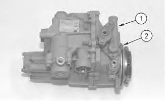
Illustration 1
1. Disconnect tube assembly (2) from primary fuel filter base (1).
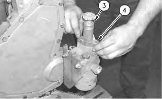
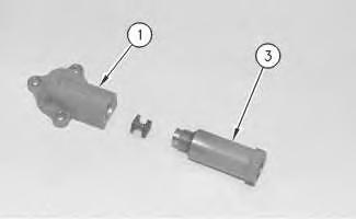
Illustration 2
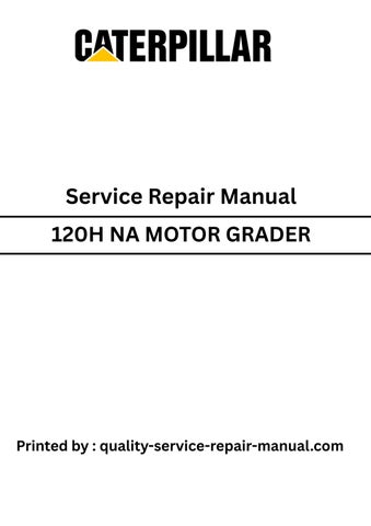
2. Remove bolts (4) from the fuel priming pump (3).
3. Remove fuel priming pump (3) from the primary fuel filter base.
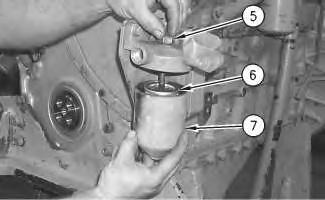
Illustration 3
4. Remove bolt (5) from the primary fuel filter base.
5. Remove filter element (6) and housing (7) from the primary fuel filter base.
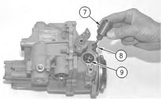
6. Remove bolts (8) from the primary fuel filter base (1).
7. Remove primary fuel filter base (1) from the engine.
Installation Procedure NOTICE
Keep all parts clean from contaminants.
Contaminants may cause rapid wear and shortened component life.
Illustration 5
1. Install bolts (8) that secure primary fuel filter base (1) to the engine.
6
2. Install filter element (6) and housing (7) to the primary filter base with bolt (5).
7
3. Install bolts (4) that secure fuel priming pump (3) to the primary fuel filter base.
Illustration 8 g00678475
4. Connect tube assembly (2) to primary fuel filter base (1).
Copyright 1993 - 2025 Caterpillar Inc. All Rights Reserved. Private Network For SIS Licensees.
Tue May 13 01:08:00 UTC+0530 2025
Previous Screen
Product: MOTOR GRADER
Model: 120H NA MOTOR GRADER 6YN
Configuration: 120H Series NA Motor Grader 6YN00001-UP (MACHINE) POWERED BY 3116 Engine
Disassembly and Assembly
446 and 446B Backhoe Loaders, Lexion 450 Combine, 3114 and 3116 Engines, IT18F Integrated Toolcarrier, D6M Track-Type Tractor and 928F, 950F and 950G Wheel Loaders Media
-SENR3611-18
Fuel Transfer Pump - Remove
SMCS - 1256-011
Removal Procedure
Note: The governor and the fuel transfer pump have been removed from the engine for photographic purposes only. This procedure may be done with the governor on the engine.
1

Illustration 2 g00623671
Personal injury can result from parts and/or covers under spring pressure.
Spring force will be released when covers are removed.
Be prepared to hold spring loaded covers as the bolts are loosened.
1. Hold cover (1) in place and remove bolts (2) in order to release the spring beneath cover (1). Remove cover (1).
3
2. Remove fitting (3) and the check valve from cover (1). Remove the filter screen (if equipped) from fitting (3).
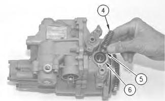
Illustration 4
3. Remove spring (4) and piston (5).
4. Remove upper O-ring seal (6).
5
This is the sample of the manual
Click on the download link for complete Manual
5. Remove sleeve assembly (7). Inspect the face of lifter (8) for excessive wear. Inspect the surface of the camshaft that is inside of the governor for excessive wear or damage.
6. Remove lower O-ring seal (9).

Illustration 6 g00623719
7. Remove fitting (10) and the check valve.
Note: For information on reusability of the components in the fuel transfer pump, refer to Guideline For Reusable Parts And Salvage Operations, SEBF8434, "3100 Governor Inspection and General Information for Mechanical Governor Groups Used in 3114, 3116, and 3126 Engines Equipped with Mechanical Unit Injectors (MUI)".
Copyright 1993 - 2025 Caterpillar Inc. All Rights Reserved. Private Network For SIS Licensees.
Tue May 13 01:08:12 UTC+0530 2025