

Previous Screen
Product: MOTOR GRADER
Model: 120H ES MOTOR GRADER 9YR
Configuration: 120H Motor Grader 9YR00001-UP (MACHINE) POWERED BY 3116 Engine
Disassembly and Assembly
446 and 446B Backhoe Loaders, Lexion 450 Combine, 3114 and 3116 Engines, IT18F Integrated Toolcarrier, D6M Track-Type Tractor and 928F, 950F and 950G Wheel Loaders
Media Number -SENR3611-18
Unit Injector - Remove
SMCS - 1290-011
Removal Procedure
Table 1
A 5P-0302 Bar 1
Start By:
A. Remove the rocker shaft and the pushrods. Refer to Disassembly and Assembly, "Rocker Shaft and Pushrod - Remove".
NOTICE
Keep all parts clean from contaminants. Contaminants may cause rapid wear and shortened component life.
NOTICE
Care must be taken to ensure that fluids are contained during performance of inspection, maintenance, testing, adjusting, and repair of the product. Be prepared to collect the fluid with suitable containers
before opening any compartment or disassembling any component containing fluids.
Refer to Special Publication, NENG2500, "Dealer Service Tool Catalog" for tools and supplies suitable to collect and contain fluids on Cat products.
Dispose of all fluids according to local regulations and mandates.
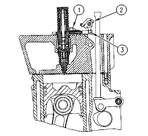
1. Remove fuel injector hold-down bolt (1) .
Note: Do not pry on the injector hold-down bracket. Damage to the unit injector could occur. The unit injector has a notch on the opposite side of the rack. This notch is used for prying the unit injector loose. Some fuel injector racks move freely when the spring is not compressed. Do not move the fuel injector rack without compressing the fuel injector spring slightly. Damage may occur to the unit injector.
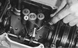
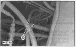
2. Use Tooling (A) to loosen the unit injector. Rotate the unit injector in order to disengage injector rack bar (3) from fuel injection control linkage (2) .
3. Remove the unit injector. Ensure that two O-ring seals are on the unit injector.
Tue May 13 01:01:46 UTC+0530 2025
Previous Screen
Product: MOTOR GRADER
Model: 120H ES MOTOR GRADER 9YR
Configuration: 120H Motor Grader 9YR00001-UP (MACHINE) POWERED BY 3116 Engine
Disassembly and Assembly
Shutdown SIS
446 and 446B Backhoe Loaders, Lexion 450 Combine, 3114 and 3116 Engines, IT18F Integrated Toolcarrier, D6M Track-Type Tractor and 928F, 950F and 950G Wheel Loaders
Media Number -SENR3611-18
Unit Injector - Install
SMCS - 1290-012
Installation Procedure
Table 1
Required Tools Tool Part Number Part
B 4C-5553 Injector Seat Cleaning Brush 1 C 173-1530 Injector Seating Tool 1
D 143-2099 Unit Injector Tool Group (Sleeve Replacement) 1
NOTICE
Keep all parts clean from contaminants.
Contaminants may cause rapid wear and shortened component life.
1. Inspect the unit injector sleeve for pitting and for carbon tracking. Used unit injector sleeves do not need to be reamed unless the seated area is pitted or eroded. If the seated area has excessive carbon deposits, the used unit injector sleeves need to be reamed. Refer to Tool Operating Manual, NEHS0675, "Using the 143-2099 Sleeve Replacement Tool Group on 3114, 3116, and 3126 Engines". Use Tooling (D) to ream injector sleeves.
2. Inspect the condition of the O-ring seals on the unit injector. Replace the seals, if necessary.
3. Lubricate the O-ring seals with clean engine oil.
1
4. Position the unit injector in the cylinder head and rotate the unit injector in order to engage injector rack bar (3) with fuel injection control linkage (2) . Push down on the unit injector and ensure that the unit injector is properly seated in the cylinder head.
Note: Do not use fuel injector hold-down bolt (1) to pull the unit injector into the cylinder head.
5. Install a new fuel injector hold-down bolt (1) in the hold-down bracket for the unit injector. Tighten fuel injector hold-down bolt (1) to a torque of 12 ± 3 N·m (106 ± 27 lb in).
Note: Do not overtighten fuel injector hold-down bolt (1) . Excessive torque may cause damage to the unit injector and the unit injector may seize.
6. Refer to the Tool Operating Manual, NEHS0738, "Using the 173-1530 Injector Seating Tool Group on 3114, 3116, and 3126 MUI or 3126 HEUI 2-Valve Engines" for the remaining steps on installing the unit injector.
7. Synchronize the unit injectors. Refer to Testing and Adjusting, "Unit Injector Synchronization - Adjust".
End By: Install the rocker shaft and the pushrods. Refer to Disassembly and Assembly, "Rocker Shaft and Pushrod - Install".
Copyright 1993 - 2025 Caterpillar Inc. All Rights Reserved. Private Network For SIS Licensees.
Tue May 13 01:01:58 UTC+0530 2025
Previous Screen
Product: MOTOR GRADER
Model: 120H ES MOTOR GRADER 9YR
Configuration: 120H Motor Grader 9YR00001-UP (MACHINE) POWERED BY 3116 Engine
Disassembly and Assembly
120H & 135H MOTOR GRADERS MACHINE SYSTEM
Media Number -SENR8544-01 Publication Date -01/10/2004 Date Updated -04/02/2016
Main Frames
SMCS - 7051-029
Main Frames, Separate & Connect

Start By:
a. remove implement pump drive
b. remove articulation cylinders
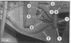
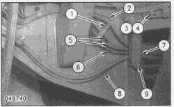
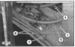
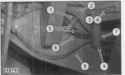
1. Remove bolt, washer and clip (1) that holds wiring harness (2), air lines (5), and clutch cable (6).
2. Remove bolt, washer and clip (4) that hold the grease lines.
3. Remove bolt and washer (3) and bolt, washer and clip (9). Remove plate and two rubber grommets (7) holding ripper oil lines (8) and air lines (5), wiring harness (2) and clutch cable (6).
4. Put identification on ripper oil lines (8) and air lines (5).
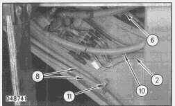
5. Remove bolt, washer and clip (11) that hold ripper oil lines (8). Disconnect ripper oil lines (8) from the control valve. Plug the fittings of oil lines (8) in order to prevent the loss of oil, and keep dirt out of the hydraulic oil system.
6. Remove bolt, washer and clip (10) that hold wiring harness (2). Disconnect the wiring harness connecters on the left side of the front frame.
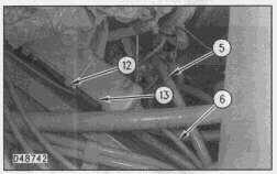
7. Remove bolts and washers (12) from cover (13) on the control box and disconnect clutch cable connection (6).
This is the sample of the manual
Click on the download link for complete Manual
Do not disconnect any air line to the machine until the air pressure in the air tank is to zero. Release the air pressure in the air tank by opening the bleed valves. The bleed valves are on the air tank underneath the rear bumper. Close the bleed valves.
8. Disconnect air lines (5) from the foot control valve.
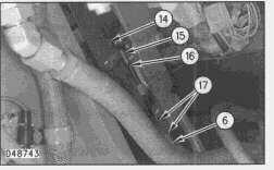
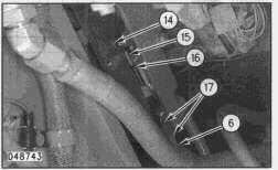
9. Remove bolt and washer (14). Loosen nut (16) on cable (6). Remove rod end (15) from cable (6).
10. Loosen lower nut (17) and remove top nut (17) from clutch control cable (6). Slide clutch control cable (6) out of the control housing.
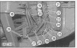
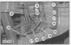
11. Remove bolts and washers (26) and plate and grommets (27) that hold air lines (23), heater hoses (18) and (20), brake cable (30), air conditioner hoses (24) and (29), transmission control cables (22), and wiring harnesses (25) and (28).
Effective July 1, 1992 regulations prohibit the venting of any refrigerant in the atmosphere. Refer to Caterpillar publication SENR3334-01, SENR5664 and NEDG5065-01 for the proper procedure, equipment and tools to reclaim refrigerant from any Caterpillar machine.
Always wear goggles when working on air conditioning systems. The system is under pressure at all times, engine running or not. Escaping refrigerant R-12 (C C12 F2 Dichloro Difluoro Methane) and refrigerant R-134A can cause freezing of human flesh. Do not smoke while working on air conditioning. Inhaling Refrigerant R-12 or R-134A through any smoking material, although not toxic or flammable, can cause violent illness. Also heat must never be applied to a charged system. See the " Air Conditioning And Heating Service Manual " Form No. SENR333401, SENR5664 and NEDG5065-01 for more information on removal and installation of lines and refrigerant from the system.
12. Remove the refrigerant R-12 or R-134A from the system. See " Air Conditioning and Heating, Purging the System, " Form No. SENR3334-01, SENR5664 and NEDG5065-01 for more information on removal and installation of lines and refrigerant from the system.
13. Disconnect air conditioner lines (24) and (29).
14. Disconnect wiring harnesses (25) and (28). Disconnect air line (19).
15. Remove bolt, washer and clip (21) that holds transmission control cables (22).
16. Remove air lines (23) from the brake air control valve.
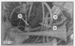
17. Remove bolts and washers (31) and cover (32) from throttle control housing. Disconnect foot throttle control cable (30). Refer to photo D48743 for clarity of removing cable.
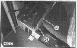
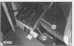
18. Remove three bolts (33) and cover (34) from the console.
NOTE: The seat assembly has been removed for better photo illustration
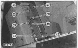
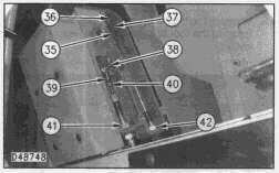
19. Remove bolt (36). Loosen nut (35) and remove rod end (37) from the transmission cable. Remove nut (42) and slide the transmission cable out of the control panel.
20. Remove bolt (38). Loosen nut (40) and remove rod end (39) from the transmission cable. Remove nut (41) and slide the transmission cable out of the control panel.
At operating temperature, the engine coolant is hot and under pressure. Steam can cause personal injury. Drain the coolant only after the engine has been stopped and the fill cap is cool enough to touch with your bare hand. Remove the fill cap from the radiator slowly to relieve pressure. Cooling system conditioner contains alkali. Avoid contact with the skin and eyes to avoid personal injury.
NOTE: Release the pressure in the cooling system by slowly loosening the fill cap on the radiator. Drain the coolant from the cooling system by placing a drain hose through the hole in the back of the bumper, attaching the hose to the drain valve fitting and opening the drain valve. Drain the coolant from the engine and cooling system in a suitable container for storage or disposal. Refer to the "Operation & Maintenance Manual" for cooling system capacities.
21. Drain the coolant system. The capacity of the coolant system is 40 Liters (11 gal U.S.).
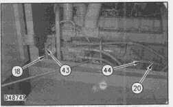
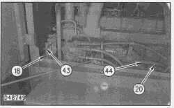
22. Loosen clamp (43) and remove heater hose (18) from left side of the engine. Heater hose has a clamp on the side of the frame.
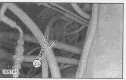
23. Loosen clamp (44) and remove heater hose (20), this hose has one clamp on the side of the block.
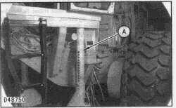
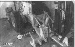
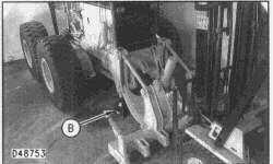
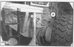
24. Remove all lines, wires and cables that were disconnected from the front and rear frames. Install the lock pin in the wheel lean bar and the front axle. Put blocks under the front wheels so they can not move. Install Tooling (A) under the platform on each side of the machine. Put a fork lift truck in position under the rear of the rear frame.
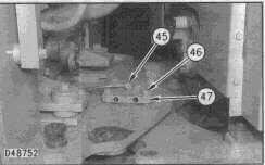
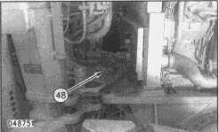
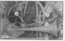
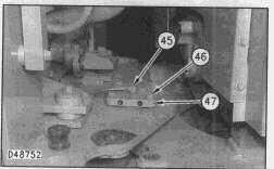
25. Remove grease line (45) from pin (48).
26. Remove bolts (46) that hold pin (48) to the frame. Install two 3/8 in - 16 NC Forcing Screws in pin (48). Remove pin (48) with the forcing screws.
NOTE: Lift or lower the frame with the fork lift truck to remove any pressure from pin (48).
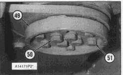
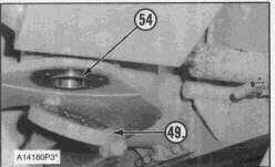
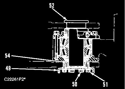
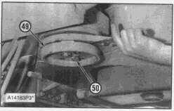
27. Remove bolts (51) that hold plate (49) to the frame. Remove bolts (50) that hold plate (49) to bottom pin (52).
28. Remove plate (49) and the shims from the frame.
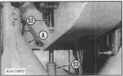
29. Put an appropriate hydraulic jack (53) in position under bottom pin (52).
30. Remove bottom pin (52) from the bottom pin bearing with the hydraulic jack.
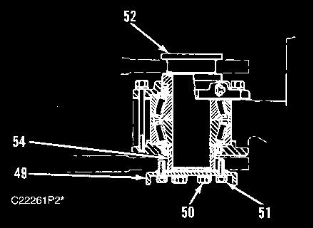
31. Remove spacer (54) from the bottom pivot pin bearing.
NOTE: Separation of the frames is not possible until spacer (54) is removed from the bottom pivot pin bearing.
32. Connect an air supply to the parking brake release valve. Release the parking brake.
33. Move the rear frame back from the front frame with the fork lift truck.
34. Put Tooling (B) under the radiator end of the rear frame. Remove the air supply from the parking brake release valve. Remove the fork lift truck. Note that Tooling (B) is under both sides of the radiator.
NOTE: The following steps are for the connection of the main frames.
35. During the connection of the main frames, check the condition of all the O-ring seals used on the hydraulic lines that were disconnected. Check the condition of any gaskets that were removed. If any of these seals or gaskets are damaged, use new parts for replacement.
36. Put a fork lift truck in position under the rear of the rear frame. Remove Tooling (B) from under the rear frame. Connect an air supply to the parking brake release valve. Release the parking brake.
37. Move the rear frame in position on the front frame with the fork lift truck.
38. Lift or lower the rear frame with the fork lift truck to get the pin bore of the bottom pin in alignment. Use a hydraulic jack to put the bore in alignment from side to side.
39. Put spacer (54) in position in the bottom pin bore bearing and the rear frame. Use bolts (51) in order to install plate (49) on the frame and hold the spacer.
NOTE: For easier pin installation, lower the temperature of the pins to -57°C to -68°C (-70°F to90°F).
40. Put bottom pin (52) in position in the bottom pin bore. Install two long bolts through plate (49) and in the bottom of pin (52) to help keep the holes in the bottom of pin (52) in alignment with the holes in plate (49).
41. Install pin (52). Remove the two long bolts.
42. Remove bolts (51) that hold plate (49) to the frame. Install two bolts (50) 180 degrees apart that hold the plate to the pin. Tighten bolts (50) to a torque of 135 ± 14 N·m (100 ± 10 lb ft).
43. Measure the distance between plate (49) and the frame with a feeler gauge at each bolt hole. Remove bolts (50) and plate (49).
44. Install a thickness of shims, the same as the minimum distance measured in Step 43, minus 0.25 mm (.010 in) on plate (49). Put plate (49) and shims in position on the bottom pin. Install all the bolts that hold the plate to pin (52) and the frame.
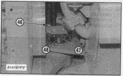
45. Put pin (48) in position in the top pin bore. Make sure the bolt holes in cover (47) for pin (48) are in alignment with the bolt holes in the frame. Install bolts (46).
NOTE: A bar can be used to put the top pin bore in alignment.
46. Tighten bolts (46) evenly to a torque of 100 ± 14 N·m (75 ± 10 lb ft) with the following procedure:
a. Tighten a bolt in the corner of the cover.
b. Tighten the bolt across from the bolt tightened in Step a.
c. Tighten the next two bolts in the other corners of the cover.
47. Remove the air supply from the parking brake release valve.
48. Remove Tooling (A) from under the front frame. Remove the fork lift truck from the rear of the rear frame.
49. Install grease line (45) to the pin.
50. Install heater hose (18) and clamp (43) to the left side of the engine. Install clamp (43) to heater hose (18) on the side of the frame.
51. Install heater hose (20) and clamp (44). Install heater hose (20) and clamp (44) on the side of the block.
52. Install all lines, wires and cables that were disconnected from the front and rear frames.
NOTE: The seat assembly has been removed for better photo illustration.
53. Slide the transmission cable in control panel and install nut (42) finger tight. Install rod end (37) to the transmission cable. Install and tighten bolt (36). Tighten nut (42) at this time.
54. Slide the transmission cable in control panel and install nut (41) finger tight. Install rod end (39) to the transmission cable. Install and tighten bolt (38). Tighten nut (41) at this time.
55. Install cover (34) and bolts (33) to the console.
56. Connect foot throttle control cable (30). Install cover (32), bolts and washers (31) to the throttle control housing. Refer to photo D48743 for clarity of installing cable.
57. Install air lines (23) to the brake air control valve.
58. Install clip, washer and bolt (21) in order to hold transmission control cables (22).
59. Connect air conditioner lines (24) and (29).
60. Connect wiring harnesses (25) and (28). Connect air line (19).
61. Position clutch cable (6) in clutch control housing. Install nut (17) to clutch cable (6).
62. Install rod end (15) to clutch cable (6) and tighten nut (16). Install bolt and washer (14).
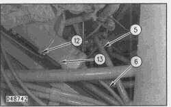
63. Install cover (13) and bolts and washers (12) to clutch control housing.
64. Connect air lines (5) to the foot brake control valve.
65. Connect the wiring harness connecters on the left side of the front frame. Install bolt, washer and clip (10) holding wiring harness (2).
66. Connect ripper oil lines (8) to the implement control valve. Install bolt, washer and clip (11) holding ripper oil lines (8).
This is the sample of the manual
Click on the download link for complete Manual
67. Install plate and rubber grommets (7) holding ripper oil lines (8) and air lines (5), wiring harness (2) and clutch cable (6). Install bolt and washer (3) and bolt, washer and clip (9).
68. Install bolt, washer and clip (1) that holds wiring harness (2), air lines (5), and clutch cable (6).
69. Install bolt, washer and clip (4) that hold the grease lines.
70. Fill coolant system to proper level. Fill hydraulic system to proper level. Recharge the air conditioning system. Refer to the Air Conditioning And Heating Service Manual, Form No. SENR5664-02, for information on removal and installation of lines and refrigerant from the system.,
End By:
a. install implement pump drive
b. install articulation cylinders
Tue May 13 01:02:27 UTC+0530 2025