

Product: MOTOR GRADER
Model: 120H MOTOR GRADER CAF
Configuration: 120H Motor Grader CAF00001-UP (MACHINE) POWERED BY 3126B Engine
Disassembly and Assembly
120H and 135H Motor Graders 3126B Engine Supplement Media
Aftercooler - Remove and Install
SMCS - 1063-010
Removal Procedure
Start By:
A. Remove the radiator guard and support. Refer to Disassembly and Assembly, "Radiator Guard and Support, Aftercooler, and Radiator - Remove".
Note: Cleanliness is an important factor. Before the disassembly procedure, the exterior of the component should be thoroughly cleaned. This will help to prevent dirt from entering the internal mechanism.
Note: Put identification marks on all lines, on all hoses, on all wires, and on all tubes for installation purposes. Plug all lines, hoses, and tubes. This helps to prevent fluid loss and this helps to keep contaminants from entering the system.

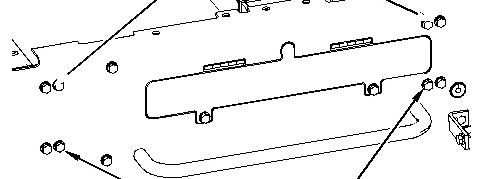

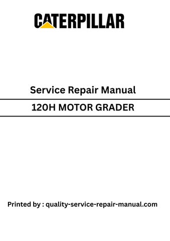
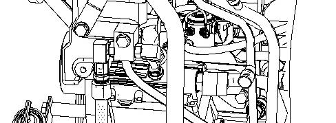
Illustration 1 g01048323
1. Remove bolts (1), (2), and (3). Repeat this step for the opposite side.
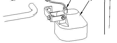

Illustration 2 g00919910
2. Disconnect harnessassembly (4) from light (5). Repeat this step for the opposite side.
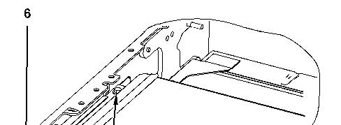
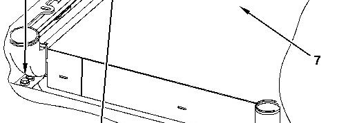

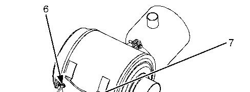
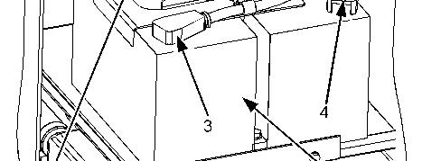
Illustration 3 g01048326
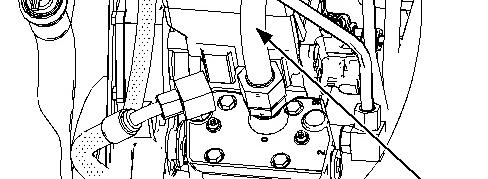
3. Position the aftercooler and the radiator in order to remove bolts (6) .
4. Remove bolts (6) from aftercooler (7) .
5. Remove bolts (8) and the spacers.
6. Use two people to remove aftercooler (7) .
Note: Do not damage the radiator.
Installation
Procedure
Illustration 4 g01048326
1. Use two people to install aftercooler (7) .
Note: Do not damage the radiator.
2. Install bolts (8) and the spacers.
3. Carefully position the aftercooler and the radiator in order to install bolts (6) .
4. Install bolts (6) on aftercooler (7) .
Illustration 5 g00919910
5. Connect harness assembly (4) on light (5). Repeat this step for the opposite side.
Illustration 6 g01048323
6. Install bolts (1), (2), and (3). Repeat this step for the opposite side.
End By: Install the radiator guard and support. Refer to Disassembly and Assembly, "Radiator Guard and Support, Aftercooler, and Radiator - Install".
This is the sample of the manual
Click on the download link for complete Manual
Product: MOTOR GRADER
Model: 120H MOTOR GRADER CAF
Configuration: 120H Motor Grader CAF00001-UP (MACHINE) POWERED BY 3126B Engine
Disassembly and Assembly
120H and 135H Motor Graders 3126B Engine Supplement
Air Cleaner - Remove and Install
SMCS - 1051-010; 1054-010
Removal Procedure Table 1
RequiredTools
6v-9512 Face Seal Plug 1
6v-9833 Cap As 1
9u-7078
9u-7095
6v-7496
Start By:
Tapered Cap/Plug 1
Tapered Cap/Plug 1
Tapered Cap/Plug 1
A. Remove the hood. Refer to Disassembly and Assembly, "Engine Enclosure (Hood)Remove".
Note: Cleanliness is an important factor. Before the disassembly procedure, the exterior of the component should be thoroughly cleaned. This will help to prevent dirt from entering the internal mechanism.
Note: Put identification marks on all lines, on all hoses, on all wires, and on all tubes for installation purposes. Plug all lines, hoses, and tubes. This helps to prevent fluid loss and this helps to keep contaminants from entering the system.

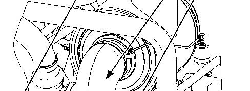
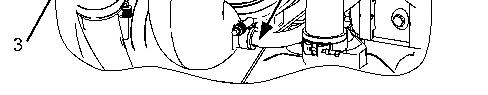
Illustration 1 g01019806
1. Disconnect tube assembly (1) .
2. Loosen the clampsand remove hose (2) .
3. Remove tube assembly (1) .
4. Disconnect hose (3) .
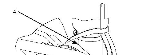
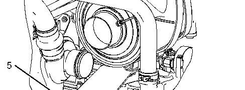

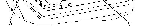
Illustration 2 g01019807
5. Attach a suitable lifting device to air cleaner (4). The weight of air cleaner (4) is approximately 27 kg (60 lb).
6. Remove bolts (5). Remove air cleaner (4) .

3
7. Remove bolts (6) and remove bracket (7) .
Installation Procedure
Note: Cleanliness is an important factor. Before assembly, all partsshould be thoroughly cleaned in cleaning fluid. Allow the parts to air dry. Wiping cloths or rags should not be used to dry parts. Lint may be deposited on the partswhich may cause later trouble. Inspect all parts. If any parts are worn or damaged, use newparts for replacement.
4
Illustration 5 g01019807
2. Attach a suitable lifting device to air cleaner (4). The weight of air cleaner (4) is approximately 27 kg (60 lb).
3. Install air cleaner (4). Install bolts (5).
Illustration 6 g01019806
4. Connect hose (3) .
5. Install tube assembly (1) .
6. Install hose (2) and tighten the clamps.
7. Connect tube assembly (1) .
End By: Install the hood. Refer to Disassembly and Assembly, "Engine Enclosure (Hood)Install". Copyright 1993 - 2020 Caterpillar Inc. All Rights Reserved.
Wed Sep 2 10:52:47 UTC+0530 2020
Product: MOTOR GRADER
Model: 120H MOTOR GRADER CAF
Configuration: 120H Motor Grader CAF00001-UP (MACHINE) POWERED BY 3126B Engine
Disassembly and Assembly
120H and 135H Motor Graders 3126B Engine
Air Compressor - Remove and Install
SMCS - 1803-010
Removal Procedure Table 1 RequiredTools
Start By:
A. Remove the fuel tank. Refer to Disassembly and Assembly, "Fuel Tank (Left Side)Remove".
Note: Cleanliness is an important factor. Before the disassembly procedure, the exterior of the component should be thoroughly cleaned. This will help to prevent dirt from entering the internal mechanism.
Note: SERVICE DATA: TOOLING (ZZ) WILL NOT BE IDENTIFIED IN PHOTOGRAPHS IN THE REMOVAL OR THE INSTALLATION. THIS TOOLING IS SHOWNIN ORDER TO ASSIST THE EXPERIENCED SERVICEMAN.
NOTICE
Care must be taken to ensure that fluids are containedduring performance of inspection, maintenance, testing, adjusting and repair of the product. Be prepared to collect the fluid with suitable containers before opening any compartment or disassembling any component containing fluids.
Refer to Special Publication, NENG2500, "Caterpillar Tools and Shop ProductsGuide" for tools and suppliessuitable to collect and contain fluids on Caterpillar products.
Dispose of all fluids according to local regulations and mandates.
Note: Put identification marks on all lines, on all hoses, on all wires, and on all tubes for installation purposes. Plug all lines, hoses, and tubes. This helps to prevent fluid loss and this helps to keep contaminants from entering the system.
1. Drain the cooling system. Refer to Operation and Maintenance Manual, "Cooling System Level - Check" for the correct procedure.
2. Drain the coolant from the cooling system into a suitable container for storage or disposal.
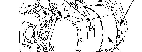
1 g01020095
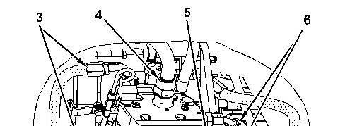


Illustration 2 g01035383
4. Disconnect hose assemblies (3) .
5. Disconnect tube assembly (4) .
6. Disconnect hose assembly (5) .
7. Disconnect hose assemblies (6) .
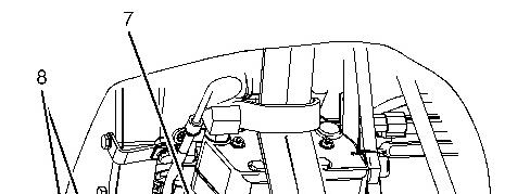
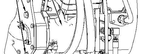
Illustration 3 g01035384
8. Attach a suitable lifting device to air compressor (7). The weight of air compressor (7) is approximately 23 kg (50 lb).
9. Remove bolts (8) .
10. Remove air compressor (7) .
Installation Procedure
Note: Cleanliness is an important factor. Before assembly, all partsshould be thoroughly cleaned in cleaning fluid. Allow the parts to air dry. Wiping cloths or rags should not be used to dry parts. Lint may be deposited on the partswhich may cause later trouble. Inspect all parts. If any parts are worn or damaged, use newparts for replacement.
Illustration 4 g01035384
1. Attach a suitable lifting device to air compressor (7). The weight of air compressor (7) is approximately 23 kg (50 lb).
2. Install air compressor (7) .
3. Install bolts (8) .
Illustration 5 g01035383
4. Connect hose assemblies(6) .
5. Connect tube assembly (5) .
6. Connect hose assembly (4) .
7. Connect hose assemblies(3) .
8. Install tube assembly (2). Install clip (1) .
9. Fill the cooling system. Refer to Operation and Maintenance Manual, "Cooling System Level - Check" for the correct procedure.
End By: Install the fuel tank. Refer to Disassembly and Assembly, "Fuel Tank (Left Side)Install".
Copyright 1993 - 2020 Caterpillar Inc. All Rights Reserved. Private Network For SIS Licensees. Wed Sep 2 10:55:11 UTC+0530 2020
Product: MOTOR GRADER
Model: 120H MOTOR GRADER CAF
Configuration: 120H Motor Grader CAF00001-UP (MACHINE) POWERED BY 3126B Engine
Disassembly and Assembly
120H and 135H Motor Graders 3126B Engine Supplement
Media Number -RENR4158-01
Alternator - Remove and Install
SMCS - 1405-010
Removal Procedure
i01963599
Note: Cleanliness is an important factor. Before the disassembly procedure, the exterior of the component should be thoroughly cleaned. This will help to prevent dirt from entering the internal mechanism.
1. Turn the battery disconnect switch to the OFFposition.

2. Remove the alternator belt. Refer to Operation and Maintenance Manual for the correct procedure.
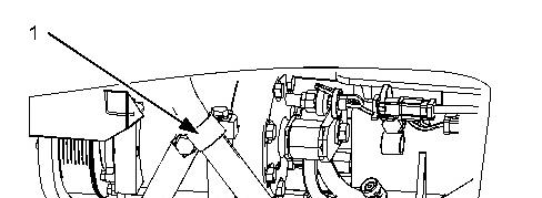
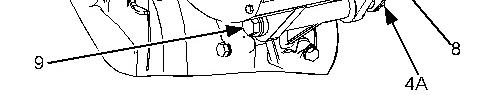
3. Remove wire assemblies (1) and clip (2) from alternator (8) .
4. Remove bolt (4A) (not shown) from belt guard (5) .
5. Remove bolt (6) from guard (7) .
6. Remove guard (7) .
7. Loosen nut (4) and position bracket (3) out of the way.
8. Remove bolt (9) .
9. Remove alternator (8) .
Installation Procedure
Note: Cleanliness is an important factor. Before assembly, all partsshould be thoroughly cleaned in cleaning fluid. Allow the parts to air dry. Wiping cloths or rags should not be used to dry parts. Lint may be deposited on the partswhich may cause later trouble. Inspect all parts. If any parts are worn or damaged, use newparts for replacement.
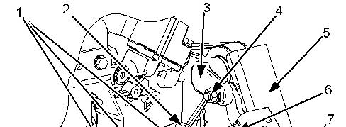

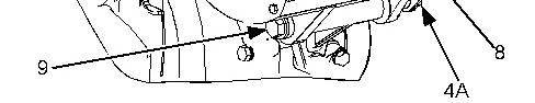
Illustration 2 g01020040
1. Install alternator (8) .
2. Install bolt (9) .
3. Position bracket (3) to the original location and tighten nut (4) .
4. Install guard (7) .
5. Install bolt (6) on guard (7) .
6. Install belt guard (5) and bolt (4A) (not shown).
7. Install wire assemblies (1) and clip (2) on alternator (8) .
8. Install the alternator belt. Refer to Operation and Maintenance Manual for the correct procedure.
9. Turn the battery disconnect switch to the ON position. Copyright 1993 - 2020 Caterpillar Inc.
Wed Sep 2 10:54:24 UTC+0530 2020
Product: MOTOR GRADER
Model: 120H MOTOR GRADER CAF
Configuration: 120H Motor Grader CAF00001-UP (MACHINE) POWERED BY 3126B Engine
Disassembly and Assembly
120H and 135H Motor Graders 3126B Engine Supplement Media
Battery - Remove and Install
SMCS - 1401-010
Removal Procedure
i01961092
1. Turn the engine start switch key to the OFF position. Turn all the switches to the OFF position.
2. Turn the key for the battery disconnect switch to the OFFposition. Remove the key.
Note: Do not allow the disconnected battery cable to contact the battery disconnect switch or the machine.
3. Disconnect the negative battery cable at the battery disconnect switch. The battery disconnect switch is connected to the machine frame.
1 g01018701
This is the sample of the manual
Click on the download link for complete Manual


2
4. Disconnect the negative battery cable (3) from battery (5) .
5. Disconnect battery cable (6) from battery (5) .
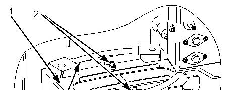
6. Remove locknuts (2). Remove battery hold down (1) .
7. Use two people to remove battery (5). The weight of battery (5) isapproximately 44 kg (97 lb). Disconnect battery cable (4) .
8. Remove bolts (7) and remove bar (8) .
9. Use two people to remove battery (9). The weight of battery (9) isapproximately 44 kg (97 lb).