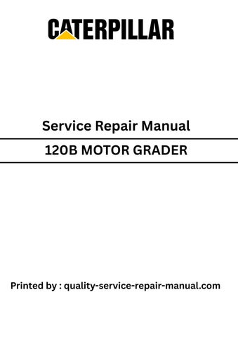
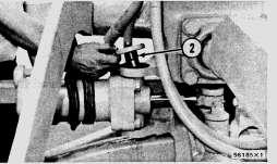
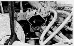
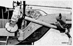
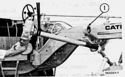
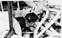
Install Steering Cylinder
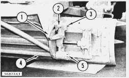
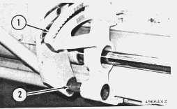
1. Fasten a hoist to the steering cylinder (1). Put the cylinder in position on the machine.
2. Put the upper pin (2) and bottom pin into position.
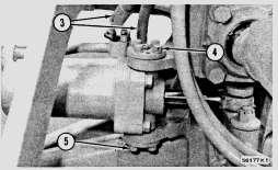
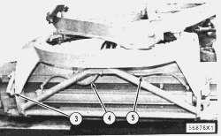
3. Install eight bolts (4) and (5) which hold the pins to the frame.
4. Install cylinder pin in rod end of the cylinder. Install the bolt and nut which hold the pin in place.
5. Install hydraulic lines (3) to the steering cylinder.
Copyright 1993 - 2025 Caterpillar Inc. All Rights Reserved. Private Network For SIS Licensees.
Tue May 13 00:57:36 UTC+0530 2025
Previous Screen
Product: MOTOR GRADER
Model: 120B MOTOR GRADER 64U
Configuration: 120B MOTOR GRADER 64U02061-UP (MACHINE) POWERED BY 3306 ENGINE
Disassembly and Assembly
NO. 120 & NO. 140 MOTOR GRADERS VEHICLE SYSTEMS
Media Number -REG01217-00
Publication Date -01/09/1972
Blade Lift Drive Housings
SMCS - 5205-11; 5205-12; 5205-15; 5205-16
Remove Blade Lift Drive Housing
start by:
a) remove blade lift arm
b) remove hydraulic tank
Date Updated -10/10/2001
1. Remove the oil from the drive housing for the blade lift and from the power control.
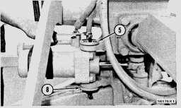
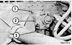
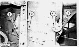
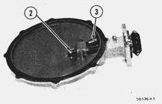
2. Remove the four bolts (1) that hold the housing (2) for the bevel pinion to the power control. Remove bolts (3).
REG012170018
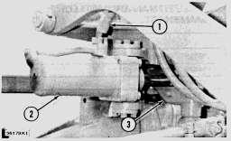
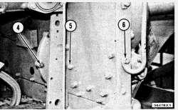
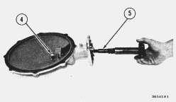
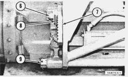
3. Fasten a hoist to the blade lift. Remove nuts (5) and bolts that hold the blade lift to the frame. Remove the three bolts (4) from the blade lift.
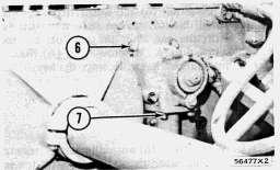
4. Remove bolts (6) that hold the grab iron to the frame.
5. Remove the bolts and nuts that hold the hydraulic filter to the frame.
6. Move the blade lift forward until housing for the bevel pinion can be removed. Remove the housing for the bevel pinion.
7. Move the blade lift as far as necessary to go past the frame. Remove the blade lift. Weight is 300 lb. (136 kg).
Install Blade Lift Drive Housing
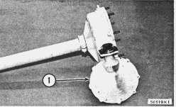
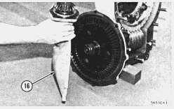
1. Put the blade lift into position in the bearing bracket (1).
2. Put the housing for the bevel pinion on the blade lift. Move the blade lift into position on the frame.
3. Install nuts (3) and bolts that hold the blade lift to the frame. Install three bolts (2) in the blade lift.
4. Install the bolts (4) that hold grab iron (5) to the frame. Install the bolts and nuts that fasten the hydraulic filter to the frame.
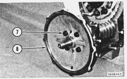
5. Install four bolts (7) that fasten the housing for the bevel pinion to the blade lift. Install four bolts (6) that hold the housing for the bevel pinion to the power control.
6. Fill the housings according to the recommendations in the LUBRICATION AND MAINTENANCE GUIDE.
end by:
a) install hydraulic tank
b) install blade lift arm
This is the sample of the manual
Click on the download link for complete Manual
start by:
a) remove blade lift drive housing
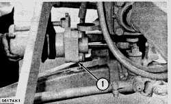
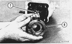
1. Remove the remainder of the bolts that hold the cover (1) to the housing for the bevel gear. Remove the cover.
2. Remove the cotter pin and nut (2) from the pinion shaft. Remove the gear (3) and washer from the pinion shaft.
3. Remove the spacer (4) from the cover. Remove the pinion shaft (5) from the cover.
4. Remove the bearings from the cover.
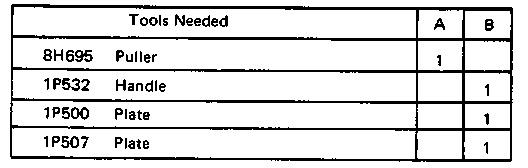
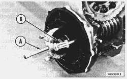
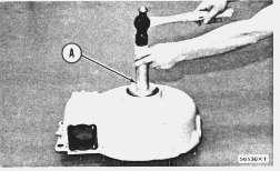
5. Remove nut (6) and washer from the shaft. Install nut (6) on the shaft until it is even with the end. Pull the gear off the taper with tool (A). Remove tool (A). Remove nut and bevel gear. Remove the key.
Do not pull gear off taper unless nut is on the shaft even with the end.
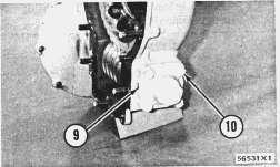
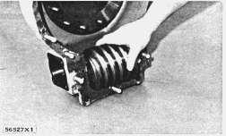
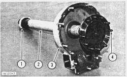
6. Remove four bolts (7) that hold the housing (8) for the bevel gear to the housing for the blade lift.
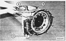
7. Remove the four bolts (10) that hold the cap (9) to the housing for the blade lift. Remove the cap and plate.
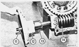
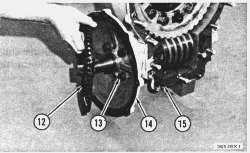
8. Remove shaft (11) from worm (14). Remove housing (12) from shaft. Remove bearing (13) from shaft.
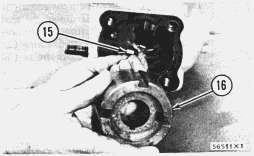
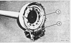
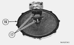
9. Remove bearing (16) and dowels (15) from the housing for the blade lift.
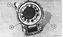
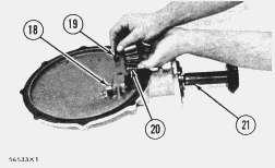
10. Remove nuts (18) and locks (17) from the worm gear (19).
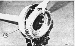
11. Remove worm gear from the housing (20) for the blade lift.
12. Remove worm from the housing for the blade lift.
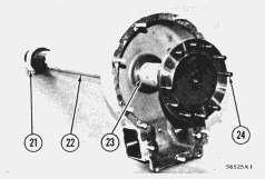
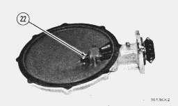
13. Loosen the two bolts that hold collar (21) in position. Slide the collar down the shaft (22). Remove the shaft from the housing for the blade lift. Remove the bearing (23) with tool setup (B). Remove bolts (24) from shaft.
Assemble Blade Lift Drive Housings
1. Install the bearing in the housing for the blade lift with tool setup (A).
2. Install bolts (4) in shaft (2). Install the shaft in the housing (3). Install collar (1) on the shaft.
3. Put the worm gear (5) in contact with the worm (6). Install the gears as a unit. Move the shaft until the bolt holes in the gear are in alignment with the bolts. Install the gear on the shaft. Install the nuts and locks.
4. Install the dowels (7) in the housing. Install the bearing (8).
5. Install the shaft (9) for the worm gear and bearing.
6. Install plate and cap (11). Install the four bolts that fasten the cap in place.
7. Install the housing for the bevel gear (10) on the housing for the blade control.
8. Install the four bolts (13) that fasten the housing (14) for the bevel gear to the housing (15) for the blade lift. Install the gear (12) on the shaft. Install the washer and nut on the shaft. Tighten to 275 to 310 lb.ft. (38,1 to 43,9 mkg).
9. Install bearings (17) in cover (16).
10. Install spacer (18) and pinion shaft (21) in cover (16). Install washer (19) and gear (20) on shaft.
11. Install nut (22) and cotter pin on shaft.
12. Install cover (16) to housing for the bevel gear. Install the three bolts to the cover and the housing.
13. Make adjustment of the worm in the following way:
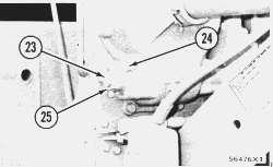
a) Be sure bolts (24) that hold cap are tightened to the correct torque.
b) Loosen lock nut (25). Turn adjustment screw (23) to remove end clearance between bearing and washer and between bearing and worm.
c) Tighten lock nut.
end by:
a) install blade lift drive housing Copyright 1993 - 2025 Caterpillar Inc. All Rights Reserved. Private Network For SIS Licensees. Tue May 13 00:57:52 UTC+0530 2025
Previous Screen
Product: MOTOR GRADER
Model: 120B MOTOR GRADER 64U
Configuration: 120B MOTOR GRADER 64U02061-UP (MACHINE) POWERED BY 3306 ENGINE
Disassembly and Assembly
NO. 120 & NO. 140 MOTOR GRADERS VEHICLE SYSTEMS
Media Number -REG01217-00
Publication Date -01/09/1972 Date Updated -10/10/2001
Blade Assembly
SMCS - 6151-11; 6151-12
Remove Blade Assembly
1. Lower the blade to the ground.
2. Loosen bolts (3) that hold the wear strips.
3. Remove the bolt and notched block (2) from the tilt bracket.
4. Remove the pin, nut (5) and washer from shaft.
5. Move the tilt bracket (1) until it is free of the end of the shaft (4).
REG012170019
6. Remove nut (6), bolt and notched block (8) from left end of the blade. Remove pin, nut (9) and washer from shaft.
7. Install a hoist on the blade.
8. Move the hydraulic cylinder until the tilt bracket (7) is off the shaft.
9. Disconnect the oil lines from the cylinder.
10. Lower the blade face down on the ground.
11. Start engine and raise the circle assembly.
12. Remove the blade assembly Weight is 1600 lb. (725 kg).
Install Blade Assembly
1. Put the blade assembly under the machine.
2. Install a hoist on the blade.
3. Start engine and lower the circle assembly.
4. Using the hoist, put the blade on the circle assembly.
This is the sample of the manual
Click on the download link for complete Manual
5. Install the tilt bracket (1) on shaft (2). Install the bolt and notched block on the tilt bracket.
6. Install the washer, nut and pin on the shaft.
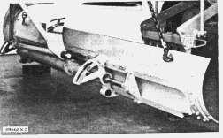
7. Connect the hydraulic lines (4) and (5) to the cylinder.
8. Move the blade cylinder to put the tilt bracket (3) on the shaft.
9. Install the bolt and notched block.
10. Install the washer, nut and pin on the shaft.
11. Tighten the bolts that hold the wear strip. Copyright 1993 - 2025 Caterpillar Inc. All Rights Reserved.