

Previous Screen
Product: MOTOR GRADER
Model: 120 MOTOR GRADER 10R
Configuration: 120 MOTOR GRADER 10R00001-02881 (MACHINE)
Disassembly and Assembly
NO. 120 & NO. 140 MOTOR GRADER POWER TRAIN
Media Number -REG01269-00
Tires And Rims
SMCS - 4202-11; 4202-12
Publication Date -01/01/1973
Date Updated -10/10/2001
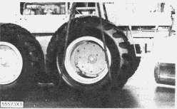
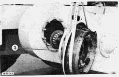
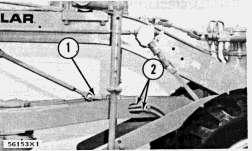
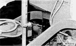
Remove Tires And Rims
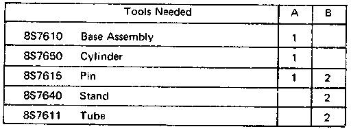
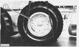
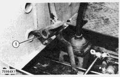
2. Fasten cables to a hoist and put them over the tire. Remove the clamps and nuts (1) from the studs.
3. Remove the tire and rim. Weight is 280 lb. (127 kg).
Install Tires And Rims
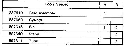
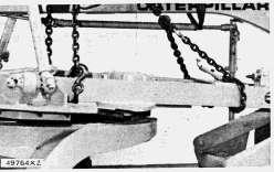
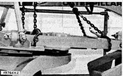
1. Put cables on tire and fasten a hoist to them. Put the tire and rim in position.
2. Install the clamps and nuts.
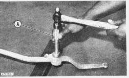
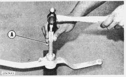
3. Remove cables and lift the rear of the machine with tooling (A). Remove the tooling (B) and lower the machine to the ground.
Copyright 1993 - 2025 Caterpillar Inc. All Rights Reserved. Private Network For SIS Licensees. Tue May 13 00:53:24 UTC+0530 2025
Previous Screen
Product: MOTOR GRADER
Model: 120 MOTOR GRADER 10R
Configuration: 120 MOTOR GRADER 10R00001-02881 (MACHINE)
Disassembly and Assembly
NO. 120 & NO. 140 MOTOR GRADER POWER TRAIN
Media Number -REG01269-00
Rear Wheel Spindles
SMCS - 4205-11; 4205-12
Publication Date -01/01/1973
Date Updated -10/10/2001
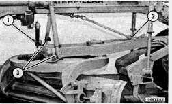
Remove Rear Wheel Spindles
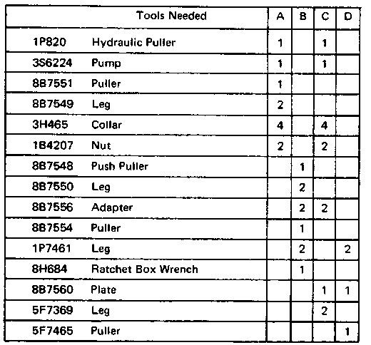
start by:
a) remove wheels, rims and tires
b) remove drive chains
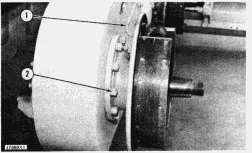
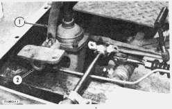
1. Disconnect brake line (1) from brake backing plate.
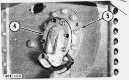
2. Remove nuts (2) from the studs that hold the cage to the housing for tandem drive.
3. Make a mark on the bearing cage and housing for tandem drive so the bearing cage can be installed in the same position.
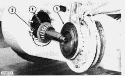
4. Fasten a hoist to the bearing cage and brake backing plate. Put two 5/8"-11NC bolts 11/2" long into the tapped holes in the bearing cage and make a separation of the cage (5) from the housing. Weight is 100 lb. (45 kg).
5. Slide the cage and backing plate out far enough to remove retaining ring (3). This will permit the retaining washer (4) to remain on the spindle shaft when hub is removed.
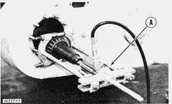
6. Remove outer bearing from cage with tooling (A).
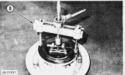
7. Remove race from outer cage with tooling (B).
8. Remove seal from outer cage.
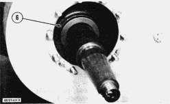
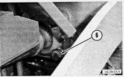
9. Remove retaining ring (6) and dowel from driven sprocket.
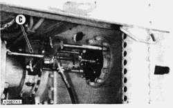
10. Lift the opposite end of the tandem drive housing. This will give enough clearance to install tooling (C).
11. Remove bearing cage from inner cage which is off center.
12. Install tooling (C) and remove the spindle from inner bearing cone. Weight is 90 lb. (41 kg).
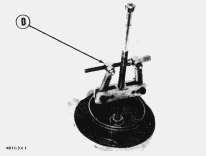
13. Using tooling (D) remove the race from inner bearing cage which is off center.
Install Rear Wheel Spindles
This is the sample of the manual
Click on the download link for complete Manual
1. Fasten a hoist and put spindle through the driven sprocket in housing for tandem drive.
2. Install dowel (1) and retaining ring (2) in driven sprocket.

3. Install seal in outer cage with tooling (A).
4. Lower the temperature of race and install in outer cage.
5. Put the retainer ring and washer on spindle.
6. Heat the bearing in oil to a maximum temperature of 275°F (135°C). Install bearing on the spindle.
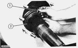
7. Fasten a hoist and put outer cage and backing plate on spindle. Install washer and retaining ring in cage (3). Connect the brake line to the backing plate.
8. Install nuts in outer cage. Tighten nuts to 140 ± 12 lb.ft. (19.3 ± 1.7 mkg).
9. Lower temperature of inner race and install in the inner bearing cage (5) which is off center.
10. Install inner cage (4) without shims. Install four nuts without lockwashers and tighten evenly to 20 lb.ft. (2.8 mkg), while turning spindle to make the bearings seat. Loosen the four nuts and tighten again to 5 lb.ft. (0.7 mkg). Measure the distance between the inner cage and the cage retainer. Install shims equal in thickness to measured dimension minus .010 ± .005 in. (0.25 ± 0.13 mm). Again install the cage and nuts.
11. Remove air from hydraulic brake lines. See BLEEDING BRAKES in TESTING AND ADJUSTING.
end by:
a) install drive chains
b) install wheels, rims and tires
Tue May 13 00:53:39 UTC+0530 2025
Previous Screen
Product: MOTOR GRADER
Model: 120 MOTOR GRADER 10R
Configuration: 120 MOTOR GRADER 10R00001-02881 (MACHINE)
Disassembly and Assembly
NO. 120 & NO. 140 MOTOR GRADER POWER TRAIN
Media Number -REG01269-00
Publication Date -01/01/1973
Speed And Direction Interlock Mechanism
SMCS - 4205-11; 4205-12
Date Updated -10/10/2001
Remove High-Low Range Selector Lever (Direct Drive)
1. Remove the cotter pin and the pin for the linkage.
2. Remove the two bolts that hold bracket to floor plate.
3. Remove the right floor plate.
4. Remove the lever (1) and bracket (2) as a unit.
5. Remove the lever from the bracket by removing the cotter pin.
6. Use tooling (A) to remove the bearings from the lever.
Install High-Low Range Selector Lever (Direct Drive)
1. Use tooling (A) to install the bearings in the lever. Be sure bearings do not cover the hole for the grease fitting.
2. Install the lever on the bracket with a washer and cotter pin.
3. Install the bracket (1) and lever as a unit.
4. Install the right floor plate.
5. Install the two bolts that hold the bracket to the floor plate.
6. Install the pin and cotter pin for the linkage.
Copyright 1993 - 2025 Caterpillar Inc. All Rights Reserved. Private Network For SIS Licensees.
Tue May 13 00:53:53 UTC+0530 2025
Previous Screen
Product: MOTOR GRADER
Model: 120 MOTOR GRADER 10R
Configuration: 120 MOTOR GRADER 10R00001-02881 (MACHINE)
Disassembly and Assembly
NO. 120 & NO. 140 MOTOR GRADERS VEHICLE SYSTEMS
Media Number -REG01217-00
Publication Date -01/09/1972
Circle Drawbar
SMCS - 6153-11; 6153-12
Remove Circle Drawbar
Date Updated -10/10/2001
NOTE: The circle drawbar can be removed with the circle assembly and blade either removed or installed.
1. Lower the blade to the ground.
2. Disconnect shaft (1) for the circle reverse and fasten it to the frame of the machine.
3. Disconnect the oil lines (2) from the front of the machine.
Fasten

5. Disconnect the link (4) for the circle centershift and fasten it to the frame.
6. Disconnect the links (3) and (5) for the blade lift.
NOTE: Keep all shims with the same links for correct installation.
7. Remove the bolts (6) and socket cap. Make identification of the shims for use during assembly.
8. Remove the circle drawbar. Weight of the circle, blade and drawbar as a unit is 3400 lb. (1543 kg). Drawbar weight is 800 lb. (386 kg).
Install Circle Drawbar
1. Fasten a hoist and position the circle drawbar on the machine.
This is the sample of the manual
Click on the download link for complete Manual
TYPICAL EXAMPLE
2. Install the cap on the ball and socket joint using the shims that were removed. Check the adjustment of the joint after the lift arms are installed.
3. Connect the links (3) for the blade lift and the link (1) for the circle centershift.
NOTE: Use the shims that were removed with the same link when installing.
4. Connect the oil lines at the front of the machine.
5. Connect the drive shaft (2) for the circle reverse.
6. Check circle drawbar and socket adjustment in the following way:
Lift the blade, then put a bar between the drawbar and the ball socket. Push the drawbar away from the socket, then remove the bar. Measure the clearance between the ball and cap. Use shims as needed to get a clearance no greater than .062 in. (1,57 mm).
Tue May 13 00:54:10 UTC+0530 2025