www.bulkhandlingreview.com
VOLUME 23, ISSUE 4 | JULY/AUGUST 2018
How to analyse and reduce equipment wear Grain handling feature Focus on digital solutions
Revolutionary
all round
HEAVY INDUSTRIAL SOLUTIONS
Electric Actuator Solutions for Bulk Handling Optimise your grain handling facility with intelligent LINAK actuators. Accurate positioning and precise feedback ensures optimised sorting and blending processes. The powerful LA36 actuator is one of the first electric linear actuators to receive an ATEX/ IECEx approval for operation in dust explosive atmospheres.
Grain Door
Diverter Valve
www.linak.com.au/business-areas/farming
CONTENTS JULY/AUGUST 2018
6 Rio Tinto delivers first iron ore with ‘world’s largest robot’ 8 CSIRO pushes MRI for mining to copper market Published by:
10 Plans for new Kangaroo Island port moving ahead 11 Tricon Equipment fills a gap in the aggregates market 12 Port of Newcastle’s bulk terminal to raise the bar
11-15 Buckhurst St South Melbourne VIC 3205 T: 03 9690 8766 www.primecreativemedia.com.au
14 Material handling equipment market to hit $190b by 2024 16 Loctite’s repair resin slashes curing times
Publisher Christine Clancy E: christine.clancy@primecreative.com.au Editor Paula Wallace E: paula.wallace@primecreative.com.au Business Development Manager Zelda Tupicoff E: zelda.tupicoff@primecreative.com.au Client Success Manager Natsha Shekar E: natasha.shekar@primecreative.com.au Art Director Michelle Weston E: michelle.weston@primecreative.com.au
17 Tough reinforced plastic from Cut to Size finds use in bulk handling 20 New nut from Infastech Engineered Fastening ideal for rough conditions 22 Safe, time-saving spherical roller bearings from Schaeffler 24 New mill head from Metso reduces downtime 26 Unique strategy to control dust emissions from Martin Engineering
44 Grant Wellwood of Jenike & Johanson looks at the best way to choose wear resistant materials 54 Flexicon drum tipper with integral flexible screw conveyor 56 Nilfisk assists industry in choosing the right vacuum for the job 67 Dr Tim Donohue writes about a project that was completed by TUNRA Bulk Solids for Roy Hill Mining
40 Metso helps coal processing plant to reduce hammer injury risk
GRAIN HANDLING 30 The Aussie designed and made bunker sweeper from Kilic Engineering
36 Bulk bag filler from Flexicon boosts malt packing output
32 BULKtalk: Observations of grain handling in South America
38 CBH Group sets new Australian record with grain train
WEIGHING & LEVEL MEASUREMENT 50 Focus on packing business: Haver & Boecker 52 Flow Force shows innovation in weighing technology
53 Emerson improves safety in solids level and volume measurement
Design Blake Storey, Adam Finlay, James Finlay Subscriptions Gordon Watson T:03 9690 8766 E: gordon.watson@primecreative.com.au
www.bulkhandlingreview.com The Publisher reserves the right to alter or omit any article or advertisement submitted and requires indemnity from the advertisers and contributors against damages or liabilities that may arise from material published. © Copyright – No part of this publication may be reproduced, stored in a retrieval system or transmitted in any means electronic, mechanical, photocopying, recording or otherwise without the permission of the publisher.
IT & SOFTWARE APPLICATIONS 58 Digital tools optimise crane performance and safety 60 Helix adds new pipe conveyor design capability
64 Taking a longer term view of ‘big data’ 66 Bentley’s latest plant design offering
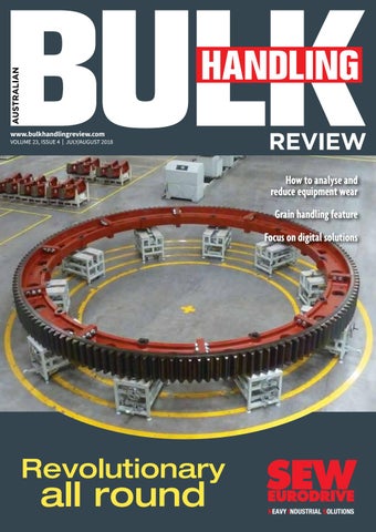
COVER STORY ADI creates revolution in segmented girth gears www.bulkhandlingreview.com
VOLUME 23, ISSUE 4 | JULY/AUGUST 2018
How to analyse and reduce equipment wear Grain handling feature Focus on digital solutions
Revolutionary
all round
sew abhr 7-8.18 frtcvr girth ring.indd 1
HEAVY INDUSTRIAL SOLUTIONS
Why has segmented girth gear technology come to the fore in recent years? SEW-Eurodrive discusses how austempered ductile iron (ADI) has enabled this revolution. Girth gears made from ADI are lighter than their traditional counterparts and feature an above-average contact fatigue strength, thanks to the cold work-hardening properties of ADI. The decreased size of the girthgear segments reduces the cost of scrapping the blanks used for casting the segments. The blanks for the segmented gears can be used without additional welding or oversizing. For the full story, see page 18.
16/07/2018 3:00 PM
Australian Bulk Handling Review: July/August 2018 І 3
EDITORIAL
ABHR to continue its partnership with industry It’s with great pleasure that Prime Creative Media publishes this edition of Australian Bulk Handling Review. As Australia’s leading businessto-business publishing company, our readers and commercial partners may be familiar with our other related titles, including Australian Mining, Process Control Engineering (PACE), Food & Beverage Industry News, and Logistics and Materials Handling. With a strong foothold in these industries, we couldn’t be more excited to welcome Australian Bulk Handling Review to our suite of products. It compliments perfectly our focus on high-growth industries that play such a valuable role in the Australian economic mix. With subjects so critical to such a broad cross section of other industries,
we at Prime Creative Media look forward to applying our editorial model to this publication, working closely with thought leaders in the industry to bring you quality content that helps individuals, organisations and industries grow. We are proud to work with our commercial partners, on bringing to the forefront the latest products and developments that help organisations run better and more efficient businesses. In this edition, we have two stories that will assist you in making decisions related to wear, whether it’s about materials of construction, the geometry of handling equipment or operating conditions. These decisions have major implications so it is important that they are informed by science, says Grant Wellwood from Jenike & Johanson page 44. On page 67 you can find a piece by
TUNRA Bulk Solids’ Dr Tim Donohue about a project that was completed for Roy Hill Mining. It involved application of the Discrete Element Method (DEM) with a wear model in order to analyse and reduce the wear of a feeder belt in the iron ore operation. Both these stories will provide information and insight that is critical to the growth of organisations and industries, along with many others you can find in this edition of the magazine. Please get in touch to discuss your feedback on the publication.
Christine Clancy Publisher - ABHR
Conveyor belts back in service in 2 hours
LOCTITE® PC 7350 Rubber Repair • • • • • • •
Improved performance in rubber repair technology Fast curing for on-site and in-situ repairs Abrasion and impact resistance Outstanding adhesion to metal and rubber Excellent elongation and flexibility Easy to apply Solvent-free
Scan the QR code to request for a FREE Sample! Hurry, limited stock available.
FREpEle Reduce Costs
Increase Efficiency
Increase Reliability
Improve Safety
www.loctite.com.au | 1300 885 556
Sam
Totally Australian made We believe pulleys with 100% local content
Our pulleys are manufactured to the highest
have an important role in the bulk materials
engineering standards for long, reliable,
conveying sector. Our locally-manufactured
fatigue-resistant service life.
pulleys offer key benefits:
So, contact Dyna Engineering when you need
• Dramatically reduce manufacturing lead time
fast turnaround time and high quality for your
• Designed to suit Australian conditions
next conveyor pulleys.
• Pulley reconditioning service available
One more thing… we deliver when we say we will.
• Designed for infinite life • Full penetration welding
Tel: 08 9473 4300 Freecall: 1800 801 558 Web: www.dynaeng.com.au Email: dyna@dynaeng.com.au
• Plain steel, rubber or ceramic and direct bond ceramic lagging • Steel plate end discs for high strength
• Keyless locking assemblies • Crowned or non-crowned available
TM
14717 A4
NEWS
Rio Tinto delivers first iron ore with ‘world’s largest robot’ The “world’s largest robot,” as Rio Tinto calls the driverless train, consisted of three locomotives with around 28,000 tonnes on board. THE TRAIN TRAVELLED MORE THAN 280 KM from Rio Tinto’s mining operations in Tom Price to the Port of Cape Lambert on July 10. Rio Tinto remains on track to complete the $940 million AutoHaul autonomous train project by the end of the year. Ivan Vella, Rio Tinto iron ore managing director rail, port and core services, said the program would deliver the world’s fully autonomous, long distance, heavy-haul rail network, operating the world’s largest and longest robots. “This program symbolises both the pioneering spirit and innovative talents of many people across Rio Tinto,” Mr Vella said. “We will continue to ensure our autonomous trains operate safely under the wide range of conditions we experience in the Pilbara, where we record more than eight million kilometres of train travel each year.” Rio Tinto operates about 200 locomotives on more
than 1700 km of track in the Pilbara, transporting ore from 16 mines to four port terminals. The average return distance of these trains is about 800 km with the average journey cycle taking about 40 hours. Rio Tinto has fitted the locomotives carrying AutoHaul software with on-board cameras to provide constant monitoring from the operations centre. It has also fitted all public rail crossings on the network with CCTV cameras.
LEFT: The AutoHaul loaded train. Image: Rio Tinto.
Conveyor blamed for Port Kembla ship blaze A conveyor has been identified as the most likely source of a major fire onboard a ship berthed at Port Kembla in June. ACCORDING TO MULTIPLE REPORTS, a fire was detected early on the morning of June 18 on the Iron Chieftan, which was unloading dolomite at Bluescope’s berth 113. “It looks like the fire actually started on the conveyor belt itself,” Fire and Rescue NSW assistant commissioner Paul McGuiggan reportedly said. “You can imagine the bearings and things around
6 І Australian Bulk Handling Review: July/August 2018
there – and that has actually transferred into the product.” According to reports, there was around a 12,000 cubic metre pile of dolomite in the hold when the fire began. There were 110 firefighters and five units daily fighting the blaze from the wharf with two Svitzer tugs spraying water directly onto the flames initially then maintaining boundary cooling duties on the hull. In all, it took five days before the fire was brought completely under control. At that stage the emergency response team handed the control of the Iron Chieftain over to the NSW police who restricted any access to the vessel until they had carried out an initial site investigation. Subsequently, the owner of the vessel, the CSL Group, decided to retire the Iron Chieftain due to the significant damage caused by the fire.
LEFT: The stricken Iron Chieftain.
ether g o T s n o ti lu o S g in c Pie
For More Information Visit
www.kockumsbulk.com.au Call 03 9457 8200 to speak to your local representative
NEWS
CSIRO pushes MRI for mining to copper market CSIRO has paired with the private sector to release a machine it says can help miners quickly sort waste ore from higher grade ores using magnetic resonance technology.
THE ANALYSER USES MRI TECHNOLOGY to rapidly identify ore grade so that large volumes of waste rock can be rejected before even entering the plant, thus reducing the amount of energy and water a minerals processor needs to use to extract product from mined ore. When they pass through the analyser, batches of ore are hit with short pulses of radio waves. The level of penetration made by magnetic resonance through the ore can help determine its grade. CSIRO believes the machine, if applied properly, can help some copper mines save as much as 20 per cent on their processing costs. The independent, government-funded research body has formed the company NextOre with its partners RFC Ambrian
and Advisian Digital, to supply the new ore sorting analyser to the international copper market. “Bringing the analyser to market through NextOre opens up the opportunity to transform the global copper industry and reduce its environmental footprint,” CSIRO research director Nick Cutmore said. NextOre has identified 59 mature copper mine sites – covering 35 per cent of global copper production – where it believes the analyser could be used to extend mine life. “The solution could also enable undeveloped, low grade mines to be brought into production, so the economic benefits are huge,” Mr Cutmore added. Over the next year, NextOre says it will focus its efforts on engaging copper producers in South America and Canada. “Contracts have been secured to provide magnetic resonance analysers to three companies, including two toptier producers, in the coming financial year,” NextOre chief executive Chris Beal said. “We are providing full ore sorting solutions, including technical and engineering advice, to move from concept to site trials and final implementation.” NextOre says the analyser can also be applied to gold and iron-bearing ores.
Replacement of Rio Tinto Paraburdoo stackers Rio Tinto has announced the construction of new stackers at its Paraburdoo mine, which is estimated to create up to 100 local jobs. RIO TINTO EXPECTS UP TO 80 Western Australian jobs to be created during the implementation phase and up to 30 Pilbara-based roles required to install the plant. “Construction and replacement of these stackers will allow Rio Tinto to work out of Paraburdoo for years to come, and importantly, create job opportunities for Western Australians,” said WA Premier Mark McGowan. Technology provider Tenova TAKRAF, is leading the design and implementation phases of the project and is committed to sourcing materials from reputable suppliers
8 І Australian Bulk Handling Review: July/August 2018
with a preference for local companies and resources. A multimillion dollar contract has already been awarded to WA business Paradigm Engineers, to provide engineering design and control system programming services to the project. The design phase of the stackers is currently underway, with fabrication to begin later this year and installation and commissioning expected to be completed by 2020. “The construction of the new stackers provides opportunities for local businesses which are well placed to win a majority of contracts generated by the works,” said Mr McGowan.
FLOWFIRST TRANSFER SYSTEM:
™
INVENTED AND PERFECTED BY OUR EXPERTS
PROVEN AND RECOMMENDED BY OUR CUSTOMERS*
Focusing on making precise adjustments to the angle and velocity of moving material — to shape the flow path and minimise impact on your receiving belts.
* To hear about our customer recommendations: marketingau@flexco.com
Phone: 1300 098 435 Email: salesau@flexco.com
www.flexco.com
NEWS
Preliminary plans for new Kangaroo Island port moving ahead Kangaroo Island Plantation Timbers (KPT) announced recently preliminary plans for a deep-water port in Smith Bay were moving ahead. THE COMPANY AIMS TO USE THE PORT, located on the northern coast of the island, as a bulk log or woodchip export facility. In a recent letter to the Australian Securities Exchange, KPT managing director John Sergeant wrote that the company was working to eliminate outstanding matters of contention before lodging its environmental impact statement for the potential port at Smith Bay, so the EIS could be lodged “in a form capable of rapid approval”. Mr Sergeant wrote that the company was undertaking refinements to the design of in-water structures to increase protection for a nearby abalone farm, and to limit the causeway footprint in deeper water, while still enabling Panamax vessels to berth safely. The company is also looking to relocate the dredge footprint “in such a way as to increase separation from the nearest sensitive receptors”. Also, Mr Sergeant wrote that the company was working to refine the design of on-land facilities and
LEFT: Kangaroo Island Plantation Timbers (KPT) plans to use Smith Bay as a woodchip export facility.
was working with local and state government to find a road route to Smith Bay. Pending the satisfactory completion of coastal process modelling for the revised in-water structure (expected in August), Mr Sergeant wrote that the company was expecting to have all outstanding matters sufficiently finalised to enable the lodgement of the EIS at around the end of the current quarter. KPT owns 25,000 hectares of productive land on Kangaroo Island, and a potential port site at Ballast Head, in addition to the one at Smith Bay.
Pilbara ports set new export record Pilbara Ports Authority (PPA) has delivered a record annual throughput of 699.3 million tonnes (Mt) for the 2017/18 financial year. THIS IS AN INCREASE OF 30.7 Mt or 5 per cent from last year’s annual throughput. In June 2018, PPA achieved a total monthly throughput of 63.4 Mt, an increase of 14 per cent from the previous year. The Port of Port Hedland achieved a record annual throughput of 519.4 Mt, an increase of 18.4 Mt or 4 per cent from the previous year. Iron ore exports for the year totalled 508.9 Mt, an increase of 14.3 Mt or 3 per cent from the previous year. Iron ore exports in June totalled 47.2 Mt, an increase of 4.2 Mt or 10 per cent from the same time last year. Imports for the year totalled 1.7 Mt, an increase of 91,000 tonnes or 6 per cent from the previous year. June imports totalled 174,000 tonnes, an increase of 7,000 tonnes or 4 per cent from June 2017.
10 І Australian Bulk Handling Review: July/August 2018
The Port of Dampier delivered an annual throughput of 177.3 Mt, an increase of 9.6 Mt or 6 per cent from the previous year. In June, the port achieved a monthly throughput of 14.6 Mt, an increase of 2.8 Mt or 24 per cent from the same month in 2017.
LEFT: Port of Port Hedland. Image: Pilbara Ports Authority
NEWS
Filling a gap in the aggregates market TRICON EQUIPMENT RECENTLY PURCHASED a 42-metre telescopic mobile conveyor, better known as the AggStack Radial Telescopic Conveyor. Tricon equipment director, Michael Tripolone said: “This is a really key gap in the aggregate market that is now filled by the Telestack AggStack range. We received the TS36 x 140 low tail and already the appetite for this unit in the marketplace is apparent. We even sold the machine before it had arrived in Australia.” The TS36 x 140 Low Tail (42m x 900mm) Radial Telescopic Conveyor rates well on durability, functionality and production rates. “I can already tell that this range will sell well in our market,” said Mr Tripolone. “Although it is an entry level unit, you can still add options so that it meets your specific needs.” Mobile equipment is a fast growing market in Australia, especially when it comes to fixed plant breakdowns. “Out of crisis stems out-of-the-box thinking and the Tricon Equipment team always deliver on a reliable, fast and effective solutions that positively impact productivity,” said Mr Tripolone. Recently, a longstanding Tricon customer experienced a bucket elevator failure, which handled woodchip delivery to its storage silo. The bucket elevator had proven to be unreliable, and a new
EFFECTIVE
RELIABLE
solution was required to continue production. After assessing the situation, Mr Tripolone and his team recommended, and supplied, a Telestack 42-metre telescopic mobile conveyor, which allowed direct loading into the silo. “This proved the most cost-effective solution not only due to the conveyor’s flexibility, which allowed it to fit the space perfectly, but also the machine’s quick installation and set-up times,” said Mr Tripolone. “With minimal downtime, production was back on track quickly, allowing the customer to meet their deadlines.” LEFT: The news AggStack TS36 x 140 Low Tail Radial Telescopic Conveyor.
ECONOMICAL
NEWS
Bulk terminal development to raise the bar The Port of Newcastle recently announced a $33 million investment in a Bulk Terminal development at Walsh Point, Kooragang Island, writes Paula Wallace. AS PART OF ITS VISION TO MAKE NEWCASTLE the cleanest and most efficient bulk handling import facility on the east coast, the Port of Newcastle is creating a bulk terminal by combining Kooragang 2 and Kooragang 3 berths under one banner. The two existing ship unloaders, which are now over 50 years old, are due to be replaced. However, the $33 million investment will see more than just the replacement of unloaders. The project will introduce state-of-the-art crane and conveyor infrastructure that will incorporate the latest in safety and environmental compliance features. “We have listened to our customers and are proud to be setting a world-class benchmark in the handling of bulk materials for their benefit,” said Port of Newcastle’s CEO, Geoff Crowe. He told ABHR that the development of the Newcastle Bulk Terminal is key to the growth and diversification of the Port’s trade. “Kooragang 2 and 3 berths are already the busiest and most diverse common user berths in the Port, handling fertiliser, meals, alumina, magnetite, cement and a range of bulk liquids commodities,” said Mr Crowe. “The new equipment will provide increased
12 | Australian Bulk Handling Review: July/August 2018
unloading capability for optimum delivery of our customers’ products to their facilities. “Improved efficiency at the berth means greater access and more volume capacity.” The new crane will be a slewing/luffing grab crane that can accommodate a diverse range of cargo types. It will be designed and built by Tenova Takraf. The new unloader will have capacity of 1,000 tonnes per hour, up from the current average rate of 230 tonnes per hour. In addition to the new crane unloader, the project includes temporary mobile hopper unloading infrastructure and environmental services. The Port will also implement direct management of the terminal ensuring the core port principle of common user access is maintained. “The Newcastle Bulk Terminal is the centrepiece of the bulk cargo precinct within the Port of Newcastle,” said Mr Crowe “It is designed to cater for a diversified cargo mix on a common user basis using common onsite equipment.” Port of Newcastle is implementing a new service model that provides a range of environmental services at the terminal. “Previously the environmental services were performed by each individual user, such as the
ABOVE: The Port of Newcastle will create the Newcastle Bulk Terminal by combining Kooragang 2 and 3 berths under one banner.
“We have listened to our customers and are proud to be setting a world-class benchmark in the handling of bulk materials for their benefit.”
stevedores, on an event-by-event basis,” said Mr Crowe. “This type of service provision lacked economies of scale and consistency of application.” The Port went to open market tender for a single service to be provided under Port of Newcastle’s direction. The environmental services will include 24/7 mechanical sweeping, equipment cleaning, post vessel berth cleaning and onsite bulk cargo waste management. Stage 2 of the Walsh Point Master Plan will include minimising cargo double handling, reducing cargo transfer points and removing trucks from the berths through the use conveyor systems. “Connecting directly with customers’ distribution sheds is critical to unlocking the environmental and efficiency improvements,” said Mr Crowe. The terminal will provide connected “surge shed” capacity for those customers whose infrastructure still requires the use of truck transfers with fully enclosed and dust-controlled truck loading after the ship has completed its discharge and departed.
Demolition underway The Port has engaged Kerman Contracting to carry out most of the development including the crane replacement, with electrical work to be performed by Downer EDI. James Rowdon from Kerman told ABHR that the project has already commenced with the demolition of the existing ship loaders and associated conveyor systems. “We are working closely with the Port of Newcastle and
other key stakeholders utilising 3D modelling which enables interactive participation, to ensure the successful delivery of this project,” he said. Some of the challenges include working around existing infrastructure and services. “We are utilising surveying services from a local surveying consultancy with a long history and a well established database of the area,” said Mr Rowdon. The scope includes the design and construction of a new 1200mtph slewing and luffing ship unloader, a new 240 metre bi-directional wharf conveyor including transfer towers at either end, associated piling and civil works, replacement of existing wharf crane rails and all associated services including water, air and electrical/control systems. The new ship unloader will be the first of its type in Australia, and claims to provide multipurpose bulk commodity unloading efficiencies superior to machines currently operating in Australia. The ship unloader will be equipped with fully integrated dust extraction system and washdown facilities. The wharf conveyor and transfer towers will be enclosed and also be equipped with washdown facilities. Water from the washdown will be separately collected for disposal. “The development is essentially split into two stages – demolition which commenced in June and will run through to September 2018, followed by new construction which is due to commence in the first quarter 2019 and will run through to end of that year,” said Mr Rowdon.
Tailored drive solutions for your Bulk Material Handling needs
®
For over 25 years, we have been providing engineered, custom solutions to our clients in Australia. Solutions they rely on. Our team is highly experienced and our product range is extensive and versatile. l Full Design, Engineering and service capabilities , Australia wide l Providing tailored drive solutions designed to supply greater productivity and less downtime l Your investment in Dana Brevini tailored solutions gives you peace of mind, with the knowledge that you have the latest innovations and technicallyadvanced drive packages to meet the most arduous of applications. Contact us NOW for more details.
1300 657 771 sales.dbau@dana.com www.brevini.com.au
MARKET ANALYSIS
Material handling equipment market to hit $190b by 2024 According to a new growth forecast report by Global Market Insights (GMI), the global material handling equipment market is achieving a compound annual growth rate (CAGR) of 5.5 per cent. GMI PREDICTS THAT THE GLOBAL MATERIAL handing equipment market will surpass US$190 billion by 2024. In the Asia Pacific region alone, GMI estimates a CAGR of 6.5 per cent from 2018-2024. Growing automation capabilities in the manufacturing space, coupled with increasing penetration of advanced technologies, are expected to drive the material handling equipment market growth. Automated material handling systems are gaining popularity with the growing trend of industries to replace human labour. RFID, IoT, and automatic identification and data capture technologies are becoming popular as they improve the order fulfillment processes and help in enhancing productivity across the supply chain. Rising labour costs in countries such as China and India will support the material handling
14 | Australian Bulk Handling Review: July/August 2018
equipment market growth. The booming manufacturing sector in the region coupled with high-cost labor is compelling manufacturers to use sophisticated machinery to ensure higher throughput . Real-time technical challenges in the operation of these systems with the requirement of high capital investment are anticipated to negatively impact the material handling equipment market. The complexity involved in the integration of hardware and software for manufacturing facilities is restricting companies that have budgetary constraints from adopting these systems. In addition, cybersecurity threats in these systems are also a factor hindering their growth. The robotics segment of the material handling equipment market is expected to experience significant CAGR of over eight per cent to reach more than US $20 billion by 2024 owing to the
IMAGE CREDIT: TOYOTA
demand for high-performance robotic systems across various industry verticals. Robots facilitate easy and fast pick and place` of material thereby ensuring accuracy and eliminating human involvement. The rising awareness about the advantages of automated systems globally will fuel the demand for robots across industries. Extensive research and development undertaken in the field of robotics and artificial intelligence in countries like Japan and China, is expected to fuel the material handling equipment market over the forecast period. The incorporation of machine learning capabilities in the robots to increase productivity with predictive maintenance are also attractive to industry. The expanding 3PL sector is expected to achieve a CAGR of over six per cent in the material handling equipment market. The increasing complexity of supply chains is compelling businesses to turn towards 3PL service providers to ensure smooth and efficient operations. 3PL service providers are focusing on real-time systems for enhanced visibility. Furthermore, the flourishing durable manufacturing sector in countries including India and China is providing impetus to the market. The growing durable manufacturing industry adopting the latest technologies for production in countries including France and Germany will support demand. The growing transportation and logistics industry in the US is providing growth opportunities to the industry value at over US$25 billion in 2017. The early technology adoption in the region and the ongoing research and development in the US will fuel the material handling equipment market demand. Stringent government regulations related to operator safety in Europe are compelling manufacturers to use highquality machines that comply with the existing standards. Companies are trying to launch new solutions and expand the product portfolio. The industry is characterised by strategic acquisitions and collaborations with technology providers to offer enhanced solutions. GMI includes bulk material handling equipment in its research scope, including conveyor belts, stackers, reclaimers elevators and other related infrastructure.
PERFECT FLIGHTS PERFECT FIT, PERFECT ALIGNMENT
Every time. Time… after time… after time Saving time and money Bulknet’s Australian made TruHelix Sectional Flights are the best in the world, due to our revolutionary production methods – the perfect fit every time! Our commitment is to deliver Section flights which leave no gap on the Center tube, matching Flight Ends, and provide the lowest cost installation/fabrication time in the market – Saving you time and money! We specialise in delivering Sectional Flights and Fully Fabricated Engineered Solutions to the Mining, Quarry, Agriculture and Civil Construction markets.
We know that every BulkNet flight will be Perfect… and that’s a big claim.
Would you like to know more?… Email: vic.sales@bulknet.com.au or go to www.BulkNet.com.au or 1800 069 675
CONVEYOR REPAIR
Repair resin slashes curing times Loctite has just globally released a new product that can repair conveyor belts in less time and without solvents, being distributed in Australia and New Zealand by Henkel. DESIGNED TO ADDRESS THE ISSUE OF DAMAGE and wear to conveyor belts, Loctite has developed PC 7350, a rubber repair PU resin that enables in situ repairs to be done extremely quickly and have the belt back in service in less than two hours. The benefits of reducing curing times lead to less downtime, which can make a big difference to mines, quarries, fossil power industries and similar operations using conveyor belts. These tend to become damaged and worn over time. Damage to conveyor belts can range from thinned areas, small cuts and tears which, if not addressed immediately, can grow bigger with time and eventually cause the entire belt to fail. Depending on the type of conveyor belt, traditional repair methods have varied from hot vulcanising through mechanical fastening to cold vulcanising. Each of those methods has downsides, like requiring expensive, heavy equipment, reducing the tensile strength of the belt and requiring rightsized spare parts. However, it’s now possible to use rubber repair PU resin, such as Loctite PC 7350, which is easy to apply, cures at room temperature and is resistant to chemicals and abrasion. Kalyan Roychowdhury from Henkel told ABHR: “This is a new product that was launched internationally a few months ago, and more recently in the Australian market.” He said the product provides two hours functional curing time with four to five minutes working time at room temperature. It has been welcomed by end users from North America and Asia due to these features, achieving strong sales since its launch. While the primary market is operators of conveyor belts, Mr Roychowdhury explains that the PU resin repair product can also be used in other applications. “Apart from conveyor belts, the same product can be used to repair rubber parts on liners in mills, hoppers, chutes and feeder bowls,” he said. “In terms of conveyor belts, the Loctite PC 7350 can be used to repair rips and tears and cuts on the skirt… it can get a belt back into operation within two hours. “There are various products that can do a similar job but they take a longer time to cure,” said Mr Roychowdhury. “Conventional products can take six to seven hours to cure and many of the products on the market are solvent based which many mines and
16 | Australian Bulk Handling Review: July/August 2018
power plants are steering away from due to hazmat risks. “The Loctite PC 7350 does not have any solventbased compound and represents a big improvement in occupational health and safety and it is very easy to apply,” said Mr Roychowdhury. The product also has excellent flexibility and high impact resistance. It can take a maximum temperature of 82 degrees, and can adhere to both natural and synthetic rubber and PVC. Henkel is currently offering free sample conveyer belt repair kits to qualified customers in Australia and New Zealand. To find out more, visit www.loctite.com. au/rubber-surface-repair-rebuild-4720.htm
ABOVE: Loctite’s new repair resin cures within two hours.
For more information call 1300 885 556 or email loctite.enquiries@henkel.com
REINFORCED PLASTICS
Tough reinforced plastic finds use in bulk handling A durable reinforced plastic composite that weighs less than aluminium but has up to 10 times the specific strength of 1020 steel is being offered by Cut To Size Plastics for demanding bulk handling, ports, and mineral processing applications. WEARPLY REINFORCED PLASTIC COMPOSITE is aimed at maintenance, engineering and fabrication tasks around infrastructure and machinery components and leaf spring assemblies. “Wearply can withstand millions of stress cycles at 1400 bar (20,000 psi) without fatigue failure,” says Pat Flood, NSW manager of Cut To Size Plastics. “Wearply derives its strength, performance and durability from epoxy resins reinforced with
continuously aligned, non-woven filaments. This allows plies to be laid so reinforcement is oriented to give greater strength and stiffness in the direction, or directions, in which it is most needed. Parallel filaments resist the stress abrasion that can shorten the fatigue life in conventional reinforced plastics.”
ABOVE: Wearply from Cut To Size Plastics is used for applications ranging from insulated rail joints, as pictured, through to vibratory conveyor leaf springs used in processing and loading equipment as well as electrical motor, generator and transformer components.
Contact: pat@cuttosize.com.au
Australian Bulk Handling Review: July/August 2018 І 17
COVER STORY
ADI creates revolution in segmented girth gears
ABOVE: SEW-Eurodrive segmented girth gears are split into several identical segments in order to keep the component parts short and easy to handle.
Segmented girth gears have a number of advantages, including simpler manufacturing, ease of transport and straightforward installation. Buy why has this technology come to the fore in recent years? Here, SEW-Eurodrive discusses how austempered ductile iron (ADI) has enabled the revolution. SEGMENTED GIRTH GEARS are used to drive large, rotating systems such as dryers, rotary kilns or horizontal mills. They are installed around the circumference of these systems, and transfer the drive torque from the gear motor to the rotary cylinder. If necessary, the rotation of the cylinder can be induced by several drives, to distribute the load. When the girth gears are used in this manner high torques can be achieved by smaller, more efficient units. Traditional girth gears generally consist of two-to-four
segments that are assembled during manufacturing for further processing. They require large and expensive machines for casting, handling and heat treatment. In contrast, SEW-Eurodrive segmented girth gears are split into several identical segments in order to keep the component parts short and easy to handle. “This is made possible by the use of austempered ductile iron when casting the girth gears,” according to David Atkinson, technical sales representative, SEW-Eurodrive. “The tensile strength of ADI is superior to that of other materials.”
18 | Australian Bulk Handling Review: July/August 2018
Segmented girth gears made from ADI are lighter than their traditional counterparts and feature an above-average contact fatigue strength, thanks to the cold work-hardening properties of ADI. The decreased size of the girth-gear segments reduces the cost of scrapping the blanks used for casting the segments. The blanks for the segmented gears can be used without additional welding or oversizing. Because of the physical properties of ADI, segmented girth gears can be constructed with a thinner face width on the gears. This has the advantage of
The number of ADI segmented girth-gear projects in Australia has increased markedly over the last 12 months, particularly in the mining sector. The trend looks set to continue.
reducing wear and noise, as well as contributing to the lighter weight and reduced material cost. And, in addition to the physical advantages, ADI enables fast manufacturing times compared to traditional methods.
More quenching The key distinguishing characteristics of ADI are introduced during the tempering stage of the iron production process. For ADI, the ductile iron is held at the quenching temperature for an extended period. This produces ausferrite, which is a matrix (or mixture) of acicular ferrite and austenite, stabilised with about two per cent carbon. Named after the British metallurgist, Sir William Chandler Roberts-Austen, austenite is a non-magnetic solid solution of iron and another alloying element. The first step in this process is to make a casting from ductile iron, which consists of traditional cast iron with the addition of magnesium and silicon. The casting is immersed in liquid salt, sometimes described by engineers as “corrosive lava”. This immersion leads to the matrix changing to austenite. The casting is then quenched, or cooled rapidly. The temperature is now reduced, and the austempering step begins. Finally, the casting is left to cool. It is then ready for use.
Enhanced properties The austempering style of quenching leads to a material renowned for its low cost, design flexibility, good machinability, high strength-to-weight ratio and good toughness, wear resistance and fatigue strength. According to the Ductile Iron Society, ADI delivers twice the strength for a given level of elongation when compared with conventional grades of ductile iron. In addition, ADI offers exceptional wear resistance and fatigue strength. For a typical component,
ADI costs 20 per cent less per unit weight than steel. During manufacture, ADI gears require around 50 per cent less energy than those made from conventional materials. Other advantages include increased machine shop productivity, reduction in weight of up to 10 per cent, reduced gear noise, rapid ‘break in’ of new gears and improved resistance to scoring. It is the cold work-hardening properties of ADI, when combined with an appropriate girth gear size, that allow for a more compact and lighter gear design than traditional solutions. This low weight is important for the handling and assembly of the girth gear, as well as for achieving circumferential velocity.
Small segments SEW-Eurodrive launched its first ADI segmented girth gears in 2008. The segmented design of the these girth gears simplifies handling at the construction site. Similarly, there is no need for special transportation. The design also guarantees an initial pitch accuracy of ISO 8, which minimises the vibrations of the girth gears. (ISO 8 is a standard that refers to the Q-number, also known as gear quality number or gear quality grade. It indicates the geometric accuracy level of teeth on a gear). Mr Atkinson says a further benefit of the design is that segments can be replaced easily, without the need for dismantling the entire ring. In addition, with the correct dimensioning, alignment, load and lubrication, an ADI girth gear is almost wearfree. This also means that spare holdings can be simplified and reduced.
“The ADI girth gears manufactured by SEW-Eurodrive are suitable for use in a variety of sectors. These include the energy sector, the pulp and paper industry, mining, the steel sector and the cement industry,” he says. The largest of these girth gears, typically used in mills, are up to 16 metres in diameter and deliver power of up to approximately 15 megawatts. In these applications, the rotation speed can be up to 20 rpm. Those used in rotary kilns are usually smaller, with diameters up to nine metres and power typically up to one megawatt. The rotation speed of these smaller girth gears is slower, typically up to two rpm. Industry is clearly taking notice of the developments in girth-gear technology. The number of ADI segmented girthgear projects in Australia has increased markedly over the last 12 months, particularly in the mining sector. The trend looks set to continue.
ABOVE: Segmented girth gears made from ADI are lighter than their traditional counterparts and feature an aboveaverage contact fatigue strength, thanks to the cold work-hardening properties of ADI.
Technical enquiries: Mr David Atkinson, (08) 9251 4900, david.atkinson@sew-eurodrive.com.au Media enquiries: Ms Sally Perry, (03) 9933 1000, sally.perry@sew-eurodrive.com.au For more information visit http://www.sew-eurodrive.com.au
Australian Bulk Handling Review: July/August 2018 | 19
FASTENING
What makes Spiralock a more stable solution?
New nut ideal for rough conditions Infastech Engineered Fastening has come up with a simple but sophisticated solution to equipment maintenance. NOT ONLY IS CONVEYOR MAINTENANCE expensive, but it can also be a safety concern, as it often requires maintenance staff to work at height using scaffolding and fall arrest equipment. Aside from the obvious distress caused when a company is faced with a safety incident, these incidents are also another financial cost. Equipment like that used in mining operations has a wide range of moving parts, and is subject to vibration and unpredictable, rugged conditions. This makes it especially vulnerable to fatigue failure. Traditional solutions include the use of adhesives, locknuts, lock wires, and lock washers to prevent thread loosening, but these methods aren’t always reliable. “For example, the application of adhesives can be inconsistent and ineffective in high or low temperatures,” said Glenn Heffernan, general manager of Infastech Engineered Fastening. “Adhesives are also single use and require cleaning off and reapplication, which adds to the cost of maintenance.” Furthermore, in constantly moving equipment such as conveyors, the last few threads of typical locknuts tend to wear down and deform, making locknuts another single-use product that cannot safely be used again. Vibration and other stressors can also deform the entire locknut, requiring maintenance crews to cut them from the
20 | Australian Bulk Handling Review: July/August 2018
bolt, meaning both the locknut and the bolt need to be replaced. To provide a solution to this problem, Infastech Engineered Fastening has produced a new fastening nut, called Spiralock, with extreme resistance against wear and tear. “Most nuts will come loose over time if they are being used in high vibration environments,” Mr Heffernan said. “In the mining industry there are some conveyor belts that are a kilometre long that depend on crews ensuring nothing has come loose. With Spiralock, this isn’t a problem.” The solution has transformed the standard internal thread profile into a self-locking female thread form with the addition of a unique 30-degree wedge ramp at the root of the thread. This wedge ramp allows male fasteners to spin freely relative to the female threads until clamp load is applied. At that point, the crest of the standard male threads is drawn tightly against the wedge ramp, creating a continuous spiral line of contact along the entire length of the thread engagement. And as clamp load increases, the wedge ramp pushes against the male thread from all sides, eliminating the radial clearance that allows fasteners to begin self-loosening under vibration. Mr. Heffernan says Spiralock fills a gap in the market for industries that need the dependability of a nut that won’t come loose.
Load distribution Research by Massachusetts Institute of Technology, Lawrence National Laboratory and others has confirmed that joints using Spiralock threads carry load much more uniformly than joints with standard 60-degree threads. The research showed that the percentage of load on the first engaged thread produced with a Spiralock tap is significantly lower – 24 per cent versus 64 per cent – with five threads of engagement. Because the uniform thread loading provided by Spiralock reduces load concentration at the first engaged thread, joint reliability is improved by minimising the likelihood of thread stripping. The Spiralock thread form also generates higher radial thread loading compared to standard threads, taking advantage of the material hoop strength and lowering the chance of shear failure. Testing performed on 1/4”28 Spiralock fasteners in conjunction with NAS62432 bolts has also shown that Spiralock can enhance fatigue life 300 per cent over standard fasteners. This is because the even load distribution with Spiralock consistently reduces the stress concentration that leads to fatigue failure. ABOVE: Equipment like that used in mining operations is especially vulnerable to fatigue failure.
Flat sensor array monitors cord damage and deviations in splices
Patented rip inserts allow rip detection in non-troughed and troughed areas.
Troughed sensor arrays identify rips immediately after critical load points.
Detect and prevent costly conveyor belt damage. Our CONTIŽ MultiProtect belt condition monitoring system, ensures your conveyors deliver optimum availability and up time, through early detection of cord damages, splice failures and costly belt rips. Upon detection of any of these issues it can send an alarm to your nominated device, It even stops the belt automatically if necessary. > Prevent costly damage • Prevent downtime incidents > Increase belt lifetime > Increase up-time, system availability and reliability > Flexible operation according to
14715 A4
your requirements Contact us now and get better conveyor belt performance for your site. ContiTech Australia Pty Ltd
+61 8 9186 0500 Karratha WA
www.contitech.net.au
+61 7 4841 9800 Mackay QLD
+61 3 9721 0600 Melbourne VIC
+61 2 8839 9600 Parramatta NSW
+61 8 6240 3500 Perth WA
+61 2 4966 3493 Beresfield NSW
ROLLER BEARINGS
Safe, time-saving spherical roller bearings Spherical roller bearings (SRB) are increasingly being used throughout Australia and New Zealand in applications involving machinery handling heavy loads at moderate speeds. SCHAEFFLER SPLIT SRB applications include an extensive range of mining, energy, bulk handling and heavy industrial processing tasks. Their robust design incorporates barrel-shaped rollers between the inner ring, which has two raceways, and the outer ring which has one spherical raceway. A benefit of this low-maintenance design is that the bearings are self-aligning because the centre of curvature of the outer ring raceway surface coincides with the bearing axis, according to Schaeffler Australia manager, industrial projects and services, Martin Grosvenor. Time-saving split spherical roller bearing technologies are purpose-engineered to minimise downtime of machinery which is vital to industries seeking to minimise production shutdowns and process interruptions. Mr Grosvenor sais these latest split SRB designs also increase safety by reducing the amount of heavy disassembly and assembly tasks typical of maintenance on machinery such as conveying equipment and primary processing plant, including timber, paper and agribusiness machinery. “In many applications, spherical roller bearings are mounted on the shaft in such a complex way that it is also necessary to remove all the adjacent components in order for it to be replaced,” said Mr Grosvenor. “This leads to long downtimes and complex additional tasks. When the split bearing version
22 | Australian Bulk Handling Review: July/August 2018
is used, most of these process steps are no longer required and the associated additional costs no longer arise. “FAG split spherical roller bearings are designed to radically simplify the process of bearing inspection and replacement, reducing maintenance downtime by 50 per cent or more – while also reducing costs by eliminating complicated bearing replacement procedures in machinery and plant.”
ABOVE: Simple inspection, rapid and simple fitting – split spherical roller bearing to be fitted in a Schaeffler SNV split plummer block housing.
Reducing time and costs Split spherical roller bearings are particularly applicable where replacement of unsplit spherical roller bearings would require costly additional work, involving the removal of gears or couplings, the dismounting of drives or the dismantling of shaft power trains. By removing many of the steps and complications involved with solid bearing replacement, the easily installed split roller bearings increase uptime and profitability. Split spherical roller bearings – which are especially useful on shafts supported at several points and locations that are difficult to access – can be applied to machinery such as bucket wheel excavators and reclaimers, winches and sheaves, worm conveyors, bucket conveyors, belt conveyors, mixing and stirring plant, mills and crushers, sintering plant, fans and ventilators, dust extraction plant and drive and transmission shafts. For further time-saving efficiencies, split spherical roller bearings can be fitted to split
RIGHT: Schaeffler split SRB applications include an extensive range of mining, energy, bulk handling and heavy industrial processing tasks.
Level Sensors with
plummer block housings produced by Schaeffler, without additional machining of the housings. Split spherical roller bearings can also generally be fitted instead of unsplit spherical roller bearings with adapter sleeves. The precondition for replacement is that the outside diameter, outer ring width and diameter of the shaft seat are identical. “Mounting downtime can be cut by about 50 per cent using Split SRBs compared with using solid bearings,” said Mr Grosvenor. “Maintenance downtime can be cut even further, to about 33 per cent compared with solid bearings, by further cutting the number
of steps involved from 10 to four. “This eliminates procedures such as disconnection of drive components, removal of shaft assemblies and removal of drive components from the shaft.” In addition to significantly reduced fitting costs for maintenances tasks, split SRBs can produce cost savings in new designs too, because plant designs can be simplified, and assembly work reduced. While the Schaeffler group is a global company, the company has expertise in Australia and New Zealand through its long-established distributor network in both countries.
Super Powers NCR-80 Radar
Mighty 80 GHz beam prevails in silos with structure
3D Level Scanner
Legendary volume accuracy with 3D visualization
Marvel at powerfully precise inventory data. Non-contact crusaders with x-ray vision overcome the densest dust with uncanny exactness.
Your Sensor Superhero
www.binmaster.com 800-278-4241 ©2018 BinMaster, Lincoln, NE 68507 USA
MINERAL PROCESSING
New mill head reduces downtime Metso was successful in replacing the ball mill head at a mine in the Philippines and resolving a costly issue in its operations. THE MASBATE GOLD PROJECT IS LOCATED ON
Higher availability and less service stoppages
Masbate Island in the Republic of the Philippines, 360 km southeast of Manila, the country’s capital. Acquired by B2Gold in 2013, the mine’s gold deposits are found on a nearby volcanic belt measuring 7 km wide. Producing more than 5,000 kg of gold last year, the mine is the Philippines’ largest operating gold project. The project’s operations are comprised of a large conventional open-pit mine feeding ore to a process plant consisting of crushing, grinding and a carbonin-leach (CIL) process step. Crushing is performed in a single stage using a jaw crusher. The grinding circuit consists of a SAG mill and two parallel ball mills, each in a closed circuit with hydrocyclones. In 2015, the mine began having issues with bolt breakage on one of their ball mill heads. The breakage originated from the trunnion to head connection and worsened with time. Masbate enlisted several engineering firms to provide advice on the breakage issue, however they were unable to resolve the problem due to the specific design of the mill head. With bolts at the trunnion to head connection continually breaking and resulting in unwanted downtime and lost production, the mine decided to act by replacing the mill head rather than continue to suffer downtime on the mill.
In May of 2016, Metso was awarded the contract to manufacture the replacement head, this time with an integral trunnion to replace the bolted joint. The service contract was then later won by Metso’s Surabaya, Indonesia Field Services department. When it came time to install the new mill head, Metso Surabaya sent two service engineers and lead mechanical fitters to the site to work in conjunction with Masbate’s own mechanical fitters. They were responsible for carrying out the installation and commissioning. The Metso team provided specialised skills and worked alongside the Masbate maintenance team to complete the head change out project on schedule, within budget and without safety incidents. The combined effort minimised lost production. Since the installation, the mine has not had any issues with the newly installed head, allowing it to improve the mill’s availability by reducing unplanned service stoppages. As a result, Metso has been awarded a second identical mill head order at the mine site.
24 | Australian Bulk Handling Review: July/August 2018
Grinding mill expertise Metso has access to a vast amount of knowledge through its engineered services groups. With the existing head coming from a third-party supplier, Metso engineers worked in conjunction with the third
“The engineering support and prompt responses Masbate Gold Project received from Metso during the entire process from assessment through to delivery was excellent.” ABOVE: In May of 2016, Metso was awarded the contract to manufacture the replacement head.
LEFT: Since the installation, the mine has not had any issues with the newly installed head, allowing it to improve the mill’s availability.
party’s engineering group using general arrangement drawings to reference some key information such as weights and general head characteristics for the 5.3 m x 7.8 m ball mill. Designing the head with an integral trunnion required considerable reverse engineering of the existing parts while adhering to the strict tolerances needed to replace the existing head. “I believe the dedication and attention to detail that we’ve shown and given has really helped cement our good working relationship” added Matt Wesson, regional product manager – ETO sales and services for Asia Pacific. “This is reflected in one way by us being trusted to further expand on our supply of wears and spares on site as well as ongoing field services work and audit opportunities that we never had previously.”
Another key factor in ensuring that the installation went smoothly was the provision of a complete installation crew flown in from Surabaya who worked alongside the mine’s own crews throughout the installation process. Jason Ives, senior maintenance advisor summed up the experience of working with Metso on the project. “The engineering support and prompt responses Masbate Gold Project received from Metso during the entire process from assessment through to delivery was excellent. “The utilisation of Metso’s field services team from Surabaya was also an excellent choice for the installation of the new head, the team is extremely professional with a good attitude to job completion and safety.”
INLOADING
OUTLOADING
The BunkerStacker3000/2000 “self-propelled” Drive Over Hopper (DOH) & Stackers are designed to make unloading grain from truck trailers into a bunker quick and easy.
For information or to order equipment for the 2018 harvest, please call 08 8268 5333 email enquiries@kiliceng.com.au visit bunkerstacker.com bunkersweeper.com
/kilicengineering
The BunkerSweeper500 is designed to make reclaiming grain from your temporary storage or shed, into trucks quick and easy.
DUST CONTROL
Manufacturer uses unique strategy to control dust emissions A conveyor technology company has helped mitigate dust emissions at the underground limestone mine of a cement production plant by implementing an innovative transfer point solution. ABOVE: The dust management system treats the material from the top and bottom during discharge.
USING A SPECIALLY-DESIGNED DUST CONTROL unit (DCU) to spray a surfactant onto both sides of the cargo stream during transfer onto the main conveyor, Martin Engineering was able to help Continental Cement Company suppress fugitive dust both along the underground belt path and during discharge at the outdoor storage yard. The result was a significant reduction in dust emissions, creating a safer workplace and offering a measurable return on investment.
An Efficient Process Continental Cement has been in operation since 1903. Over more than a century, the company has continued to improve and increase operations to reach a current cement production capacity of 1.1 million tonnes of clinker annually. A 106 m underground mine now provides the primary source of limestone, which makes up 75
26 | Australian Bulk Handling Review: July/August 2018
per cent of the raw material required to produce the meal in the company’s Type I/II, and Type III Portland cement. Yielding 1.4 million tonnes of limestone annually, the extracted material is transported via truck and high-speed conveyors in order to move it to the surface, where it is held in a 91,000 tonne outdoor storage pile, then processed through a four-stage preheater/precalciner dry process cement kiln. Trucks dump 544-589 million tonnes per hour of extracted limestone into an underground hopper that feeds an impact crusher, which reduces the rocks to 101 mm minus. The aggregate is then loaded onto Conveyor 0, a 1524 mm wide belt travelling approximately 3.5 metres per second for 122 m. The rock is discharged through a transfer chute onto Conveyor 1, travelling up the 400 m inclined belt to the surface and dropping 6 m onto the outdoor storage pile.
The right part for the job - Metso Megaliner™ minimizes downtime and improves safety That’s how we make the big difference, the Metso Way. Every grinding mill is unique. They do however have one thing in common. They need to be operational. Liner changes need to happen quickly and safely. Every day we work to find new and better ways to keep mills around the world up and running. Experience from over 8,000 mills world-wide combined with the market’s widest range of grinding wear parts and services means we can select exactly the right solution for your mill. The new Metso Megaliner™ reduces your downtime by minimizing the number of parts and people inside the mill. This speeds up installations and provides a safer working environment. What makes your grinding mill unique? Make sure you have the right parts for the job with Metso. Find out how Metso grinding wear parts and services can make the big difference for your mill at metso.com/GrindingWearParts #TheMetsoWay
DUST CONTROL
ABOVE: Monitors, valves and boosters are in accessible cabinets, so the system is easy to inspect and maintain..
”The two main areas we identified as having unacceptable dust emissions were at the underground crusher hopper and outdoors where the material was discharged onto the stockpile,” said environmental manager Leonard Rosenkrans.
An effective solution The original dust control equipment followed a traditional approach, with a goal of wetting the surface of the cargo. However, operators learned that limestone dust was not being adequately controlled by the water alone. Martin Engineering representatives visited the site with a trailer containing a fully functional Martin Dust Control Unit (DCU), allowing a full demonstration of the unit’s capabilities. Conducting an end-to-end walkthrough of the cargo flow, technicians were able to determine the best course of action. “After inspection, we devised a plan that optimised the dust control at both locations, while using as much common equipment as possible,” said Brian Nance, product engineer at Martin Engineering. A six-nozzle cradle-mount system was installed to provide serviceability at the Conveyor 1 discharge, and a manifold system was placed to address the issues at the dump pocket. Material monitoring sensors were employed at both locations to ensure application only when needed. The pumps in the DCU are powered by variable frequency drive (VFD), allowing independent control over the flow of water and chemicals for each pump. The proprietary Martin MEL-101 chemical binder additive is dosed at the proper ratio to suit the operating conditions.
28 | Australian Bulk Handling Review: July/August 2018
The entire system is integrated with the plant’s control system, so that it can be monitored remotely. With an approximate 300:1 water-to-additive ratio, the MEL-101 supports the water’s role in providing dust suppression using economically concentrated volumes. To control costs, the VFDdriven pump regulates chemical flow by releasing chemical only when material is detected on the conveyors. Nozzles were placed at the hopper mouth, so the DCU could spray treated moisture inward toward the impact zone. By keeping the particles within the material flow, the new dust control system helps minimise health and safety issues, reduce wear and tear on equipment and create a better work environment.
Final results After some fine-tuning to obtain the optimal chemical-to-water ratio, as well as proper sprayer placement for best coverage of the cargo flow, the system has eliminated most visual signs of dust emissions and has drastically improved air quality in and out of the mine. “It’s almost like a light switch,” Mr Nance said. “Turn the DCU on and the dust is no longer present at either of the emission points. Turn it off and within a few minutes, the dust returns.” There are 22 employees in the mine. The cost of cement industry dust to society and workers has been studied in depth by the US EPA to justify dust regulations.1 The cost of the installation was about $50,000 and the annual maintenance and chemical costs are about $35,000 per year.
REFERENCE: 1. https://www. epa.gov/sites/ production/ files/2016-04/ documents/ria_ cement-2010.pdf
LEFT: Integrating the system with the plant’s PLC helps operators to monitor and adjust chemical outputs.
“After inspection, we devised a plan that optimised the dust control at both locations, while using as much common equipment as possible.”
The five-year net present value of the costs plus the investment is about $200,000. Using the data from the EPA report, the benefit to society created by Continental from being proactive in the mine is about $375,000. So, the intuitive decision to be proactive in protecting the workers and surrounding neighbourhoods was a wise choice. There are many ways to look at the direct benefit to the company, including reduced health and safety issues as well as increased equipment life. Sometimes it pays just to do the right thing. “The Martin team has gone above and beyond to make sure everything is operational and efficient,” Mr Rosenkrans said. “We are currently considering a service contract for the new dust system, and potentially including the company’s onsite belt cleaner blade replacement service as well. From our first encounter, we’ve had a positive experience... and we’re very satisfied with the result.”
Martin Engineering, based in the United States, is an industry leader in developing and manufacturing flow aids and conveyor products around the world for a wide variety of bulk material applications, including coal, cement/clinker, rock/aggregate, biomass, grain, pharmaceuticals, food and other materials.
For more information visit www.martin-eng.com
WHEN RELIABILITY MATTERS
USE
AUTOMATED LUBRICATION SYSTEMS •25bar of pressure •Ability to pump lubricant 8m •Can be used as single and multi-point lube system •Sizes range from 120, 240, and up to 480cc.
WWW.SLSOLUTIONS.COM.AU
BELOW: With Conveyor 0 running in the background, the air is clear and the work area is compliant.
SALES@SLSOLUTIONS.COM.AU
GRAIN HANDLING
The Aussie designed and made bunker sweeper After three years in research and development, the BunkerSweeper from Kilic Engineering is now available to the market, writes Paula Wallace.
LEFT: Jason Kilic with the BunkerSweeper – designed and made in South Australia by Kilic Engineering.
IT’S TAKEN THE TEAM AT KILIC ENGINEERING just a few short years to come up with a novel and effective design for a bunker sweeper that will slash operational costs and make the task of moving materials from the bunker to truck more efficient than ever before. Managing director, Jason Kilic told ABHR: “This is the fourth iteration of this product… it’s something we’ve heavily invested in. “Of course things always look simpler and cheaper on paper,” he says. “It is somewhat different from what we first had in mind. It was going to be more of a slave device and the intent was to couple it with a stacker conveyor.” The more the Kilic team tested the product, the more they released it needed to be self-propelled, independently operated and manoeuverable. “That was what we learnt from the extensive trials we did,” said Mr Kilic. The final BunkerSweeper, with a design capacity of 500 tph (18,000 bushels), features a single-person platform where an operator can easily control the machine. “The controls also allow you to swing it back and
30 | Australian Bulk Handling Review: July/August 2018
forth, you can lift it up and down. It’s almost like a four wheel drive, where you have rear and front height adjustment,” said Mr Kilic. With much interest coming from the midwest of the United States, Kilic Engineering is aiming to get a unit “on the ground” there this year. “There’s nothing exactly the same on the market,” said Mr Kilic. “There are some similar products but they are very agricultural in comparison, they don’t have the flexibility our machine has or the maneuverability.” Quite simply, the BunkerSweeper takes product from a stockpile or ground pile and moves it up an elevator onto a conveyor and then into a truck or onto another conveyor. “The end game is getting it into a truck or container… the reason we’ve designed it is to eliminate the need for a front end loader,” said Mr Kilic. “When we studied the operational habits of bunker sites, they were heavily reliant on front end loaders, which are expensive, involve big capital outlay and come with costs in repair, maintenance and fuel.
“It was done in-house with all our own people, we pretty much collectively used our knowledge and expertise in the grain industry”
RIGHT: The BunkerSweeper was designed as a cheaper alternative to front end loaders.
“We wanted to come up with a cheaper alternative, something that was easy to use, safe to use and specific to a range of bulk material products,” he said, adding that the range of products include wheat, corn, soybean meal, fertiliser and sand to name a few. Mr Kilic said using a “back of an envelope calculation”, operators could save up to 50% on operational costs. “You can either connect it directly to a power supply, plug it into mains or at more remote sites, where they don’t have power, they can use a diesel generator to power it,” he said. The machine has two powerful augers that draw the material into the centre, into the elevator throat, from where it is delivered up the middle via a bucket elevator before being discharged onto a swing conveyor. “That swing conveyor has a 90 degree range, so can swing from side to side,” said Mr Kilic. All the research and development on the BunkerSweeper was done in South Australia, with trials conducted in New South Wales. “It was done in-house with all our own people, we pretty much collectively used our knowledge and expertise in the grain industry,” said Mr Kilic. “We also sought feedback and input from our customers in the grain industry and spoke to them about operational requirements and their wants, likes and dislikes.” While there is interest in the BunkerSweeper in Australia, Kilic Engineering has its sights set on the US market. “We’ve already sparked a lot of interest in the US and we do have customers over there wanting it now,” said Mr Kilic. The Bunker Sweeper is fully manufactured in South Australia by Kilic and can be produced within six weeks.
BINTECH SYSTEMS DRY SOLID FLOW SOLUTIONS SWR ENGINEERING
MaxxFlow HTC
Flow Measurement for Dry Bulk Solids • Powder • Dust • Granules
• High Temperature • High Pressure
“We’re just going into production now and the good news is that we’ve sold three units already,” said Mr Kilic, adding that they will be delivered to the customer’s site in November.
M-Sens 2
Online-Moisture Meter for Solids For more information visit www.bunkersweeper.com
• Powder • Dust • Granules
• Bins • Feeders
• Conveyers • Mixers
FlowJam
Material Blockage/ Empty Pipe • Powder • Dust • Granules
• High Temperature • High Pressure • Non Contact
TOLL FREE 1300 363 163 sales @bintech.com.au www.bintech.com.au
GRAIN HANDLING
talk
Observations of grain handling in South America This article includes the latest practices in grain handling from terminals visited in Brazil and Argentina, the two major exporters of South American grain.
STEVE DAVIS In his regular BULKtalk column, Steve Davis* of Rio Tinto considers the basics of bulk handling that sites often struggle with. In May/June 18 he looked at safety issues in bulk material handling systems. *Steve Davis is the principal advisor – bulk materials process at Rio Tinto, based in Perth. Steve has worked in bulk handling for 30 years, for both resource companies and professional engineering firms, in Australia, South Africa, the Middle East and Canada. His experience encompasses such commodities as iron ore, coal, potash, phosphates, petcoke, sulphur, sands and grain.
THE TERMINALS IN BRAZIL WERE in Barcarena located near Belém on the mouth of the Amazon River; and in Santos, near São Paulo on the east coast. Those in Argentina were in the San Lorenzo-Puerto General San Martín Port Complex and at Arroyo Seco, both on the Parana River near Rosario, and in the Port of Ingeniero White in Bahía Blanca on the South coast of Buenos Aires province. All these port locations have several grain terminals in operation due to the quantities of export grain in season, limited location of suitable ports, and there being an open and competitive market for the service of receival and loading of grain to ships that has resisted consolidation. Many terminals are on land that is owned, or in some cases leased, by well-known international grain traders, who also operate the facilities. Most of the terminals receive and store several types of grain. Some also receive and store soybean oil. Brazil exports approximately 50 million tonnes of wheat, corn, rice and soybean and smaller amounts of other grains. Argentina exports approximately 70 million tonnes of similar grains. Like all agricultural producers, this tonnage is variable and affected mainly by weather. Other variables include political controls on land use and export duties. In a good year, during the main harvest the terminals operate 24/7 for many weeks on end. At other times the terminals may operate as little as two or three day shifts a week.
Transport to terminals Grain is often transported to the terminals over long distances. Transport methods to the terminals include barges, rail and road vehicles. Travel of over
32 | Australian Bulk Handling Review: July/August 2018
1,000 km to ports is not unusual for all three methods. All terminals can receive by road, some have road and rail feed or barge and road feed, and some have all three options. From observation, it seems that well over 50 per cent of the grain is transported in by road. We were advised that the condition of the roads varies from little more than tracks to reasonable surfaced highways. Some of the larger terminals only have facilities to receive by road. Typical vehicles in Argentina are rigid trucks with dog trailers, although there are some B doubles and articulated semi-trailers. In Brazil, B doubles and semis were more
BELOW: South American ports visited.
RIGHT: Drive through truck tippers in Argentina.
common. The diversity in configuration and age of vehicles is large. There is a combination of farm owned and contract fleets. Road transport offers flexibility in capacity and destination necessary in the variable market. Vehicles are marshalled in large areas to coordinate unloading of grains in sequence, either as an integral part of the terminal, or remote from terminals depending on space. Road access in and around the terminals is surprisingly poor and has arbitrary coordination. Bahia Blanca, for example, has a shared facility for marshalling trucks that has capacity for some 4,000 or more vehicle combinations that park before and after sampling. Vehicles leave in batches to deliver grain to the terminals. This area is six kilometres from the port. On arrival, trucks are weighed and grain is sampled. Remote control probes with vacuum conveying to the lab is typical. Grain is categorised immediately in site laboratories. If the grain is acceptable, the trucks then join queues to unload. Trucks are weighed again immediately after unloading. Independent truck drivers assess the delays at the port and head for the terminal with the shortest unloading time. Total unloading cycle time can be many hours. Trucks are unloaded through rear discharge gates in the trays. As the truck, trailer combinations do not have tipping bodies, unloading is through truck tippers, also called unloading platforms. These tippers are not in common use in Australia, but are widely used through North and South America for bulk unloading. Truck combinations drive into the fully enclosed building containing the tipper
platform, and the entire coupled combination tilts to an angle at which the grain flows from the rear gates. Cycle time is several minutes, and the tipper platform is drive through after unloading. Multiple tipper installations were common; one terminal visited had five in operation. Tipping platforms can be over 60 metres long and tip to approximately 35Â degrees. Barge transport requires additional transfer facilities from truck to barge at regional river terminals. Barge unloading at the main terminals required unloading facilities. Both loading and unloading facilities add cost to operate and maintain, but this allows grain traders to consolidate loads earlier in the logistics train. In Australia, US and Canada, regional rail hubs (elevators) provide similar consolidation of grain for transport. The transition to barge transport, with shorter road transport distances is ongoing. New barge unloading facilities were being, or had just been, built at several river terminals. Other terminals have been unloading barges for many years. Both vacuum and Siwertell type unloaders, and a few older grab cranes were in use. Direct transfer from barge to ship, as seen in some US and other ports, was not in use, as river currents are too high. Rail transport requires transfer from truck to train and unloading to the terminals. The rail network in both Brazil and Argentina is relatively basic. All ports except Barcarena have rail connections, but there are few regional hubs for grain collection. Rail cars were top loaded and bottom
materials handling asset life extension infrastructure
ASPEC Engineering provides high quality technical engineering support to mines and ports
www.aspec.com.au
Australian Bulk Handling Review: July/August 2018 | 33
GRAIN HANDLING
RIGHT: Grain barges on the Amazon River.
discharge. Both loop and siding systems were in use for unloading with discontinuous single wagon unloading operation being the normal method. Santos has the best rail delivery set up, with about 50 per cent of grain delivered here by rail. Direct loading from barge, truck or train to ship is usually possible in the terminal materials transfer configuration but only when topped up from storage. This was infrequent because there needs to be a ship being loaded at the same time and with the same grain type being delivered.
Grain terminal storage Grain terminals generally have a variety of storages for grains and reflect expansion changes over time. Storage includes steel and concrete silos, rectangular bins, and several types of linear stockpiles (flat warehouses). More recent storage facilities seem to be all linear storage. Typical total
RIGHT: Twin slewing, telescoping boom shiploader installation in Brazil.
34 | Australian Bulk Handling Review: July/August 2018
storage capacities are from 100,000 tonnes through to 250,000 tonnes. All permanent storage was top filled and reclaimed by gravity discharge from below. Some sites had space for “overflow” storage in large plastic “sausage” bags. These were manually filled and discharged. Grain transfer around the terminals mostly uses a combination of bucket elevators and conventional troughing belt conveyors, with some other conveying systems noted. The older terminals, where expansions and changes have taken place have a web of conveying systems from unloading facilities to the different storages, often with ability to divert between storages. All conveyances are fully enclosed to keep the ever-present bird populations at bay. Conveyance designs were conventional. Most conveying rates were relatively low, with the highest capacities at shiploading. The highest capacity for loading noted was 2,500 tonnes per hour.
Materials Handling Solutions
Technical Support
Spare Parts Partnership Programs
Maintenance
Training
Powder Handling Shiploading Grain is loaded to seagoing vessels at the terminals. There are draft limits in all ports, either from river dredging or river mouth sandbars. This results in partial loading of Panamax size vessels, or smaller vessels being fully loaded in the river ports. Partial loads can be topped off at other ports that have less draft constraints, such as BahĂa Blanca and Santos, even in Montevideo, where high tide draft is sufficient for PostPanamax vessels. Rosario has a road bridge downstream of the grain terminals at the San Lorenzo-Puerto General San MartĂn Port Complex, that imposes additional clearance limitations. The quantity of grain exported by the terminals varies from under one million tonnes to about 10 million tonnes. Some customers order mixed grain cargoes. Terminals use belt conveyors to feed twin or triple gravity tube loading spouts, or twin or triple fixed, slewing and telescoping boom loaders. Some travelling luffing boom shiploaders are also in use. Dust is always an issue when loading, and this is managed in several ways, without any direct application of surfactant to the grain. Boom loaders use telescopic shrouds that reach down into ships holds. Some of the spout loaders use a water spray curtain that captures dust that is blown away from the loading points. All seem to use a variation in tarpaulins to minimise the exposed hold opening. Loading ceases as soon as there is any sign of rain or snow. For Barcarena particularly, this means a significant extension in load time as there are many rain events. Overall, the terminals visited were in good condition. The equipment was competent and fit for purpose. Construction and engineering is similar to Australia. There was good attention to health and safety, with good policies and reinforcement and historical accident and incident data. Dust extraction systems were evident, but design could have been better. Guarding and access was relatively good, considering the age of some of the facilities. There were obvious innovations to improve safe practice. The newer facilities showed best practice in health and safety. There was little spillage evident, likely because that grain handling is well understood and consistent, and the varying rates of operation provide time for maintenance. Spillage is cleared quickly to avoid attracting pests. In summary, there are many differences between these and Australian grain terminals and the way they are operated, with just a few similarities.
Proven turnkey systems for powder processing industries. Delivery to dispatch.
Packing & Palletising
Clustering
Shrink Wrap
Wrap Around
Lifting Systems
Ergonomic solutions for manual handling tasks.
(03) 9457 8244 Call to speak to your local representative www.kockumsbulk.com.au
GRAIN HANDLING
Bulk bag filler boosts malt packing output When a malt manufacturer in the UK needed a more efficient system to pack pale ale malt into 350 kg to 1,000 kg bulk bags, it found a solution from Flexicon. MOST OF THOMAS FAWCETT & SONS’ MALT was previously supplied in 25 tonne bulk lorry loads and 25 kg sacks. When the company first supplied malt in bulk bags, members of the malting staff transferred batches of malt from pre-weighed 50 kg sacks into bulk bags by wheeling the sacks on a sack truck on the upper floor and tipping them into a bulk bag held on a forklift truck on the floor below. This was a three-person job: one filling sacks, one
36 | Australian Bulk Handling Review: July/August 2018
tipping sacks, and one operating the forklift truck. Installation of a Flexicon TWIN-CENTERPOST Bulk Bag Filler and flexible screw conveyor in the packing room area has created a more flexible packing operation and saved operators from double handling of the malt. Brian Hickman, Thomas Fawcett & Sons’ malting manager, says, “By installing the bulk bag filler, we save between six to eight hours of operator time each week”.
ABOVE LEFT: Bag spout is connected before malt is transferred from a silo through a horizontal flexible screw conveyor and downspouting into the bulk bag filler inlet. ABOVE RIGHT: With the bag inlet secured to the downspouting, the automated weigh-filling cycle is initiated.
How bulk bags are now filled
A bulk storage silo was fitted with a charging adapter for connection to a Flexicon horizontallyoriented flexible screw conveyor 7.5 m long and 168 mm in diameter. From the conveyor’s discharge housing, malt flows through downspouting to the bulk bag filler inlet.
The bulk bag filler is equipped with an adjustable fill head that can be raised or lowered to suit all popular bag heights, and secured in place with two quick-release pins. An oversized filling spout accommodates open-top bulk bags. Mounted on load cells, the unit can weigh-fill 350 to 1,000 kg of malt into bulk bags. To fill a bag, the operator positions a 1200 x 1000 mm pallet on the filler deck and attaches the bag loops to each of four retractable bag hooks on the fill head. The operator secures the bag inlet to the downspouting. The system’s PLC runs the flexible screw conveyor at a high feed rate, reducing the feed rate to trickle before stopping the conveyor when the accurate target weight has been loaded into the bag. The bag and pallet are removed by pallet jack. “Individual customer orders are typically 24 one-tonne bulk bags of malt,” says Mr Hickman. “The system works well and we are pleased with the reliable operation it provides to our malting facility. “The bulk bag filler and flexible screw conveyor operate separately from our 25 kg sack filling system, providing another advantage as we can now do both operations simultaneously, saving time and increasing production. “We fill the bulk malt outload silo in the evening when the 25 kg sack line is not running, and then we can pack simultaneously during the day,” he said.
Designing, manufacturing and installing bulk solids storage and handling solutions world wide.
Kotzur Pty Ltd
60 Commercial Street, Walla Walla NSW 2659 Ph (02) 6029 4700 www.kotzur.com
Kotzur Bulk Solids Handling Pty Ltd formerly Downfields Engineering Pty Ltd
19-29 Enterprise Street, Wilsonton Industrial Estate. Toowoomba QLD 4350 Ph (07) 4634 4622 www.kotzur.com
GRAIN HANDLING
CBH Group sets new Australian record with grain train CBH GROUP HAS BROKEN ITS previous record for the longest and largest grain train operated in Australia. The single 1.8 kilometre train with 120 wagons and three locomotives delivered over 9,000 tonnes of wheat to CBH’s Kwinana Grain Terminal, earlier this year. The movement broke its previous grain industry record of 88 wagons back in July 2016, which contained 6,500 tonnes of wheat and was 1.3 kilometres long. CBH general manager operations David Capper said the record train was part of a trial undertaken to better understand how CBH could transport grain in the most efficient and cost effective way possible.
“When we made the rail investment back in 2010-11 and partnered with our rail operator Watco, the overwhelming driver was to take control of above rail operations and deliver our growers the most efficient transport service possible,” Mr Capper said. “In that first year, we were able to reduce freight rates by seven per cent and while these reductions have continued – rail freight rates are about 20 per cent lower now than in 2010-11 – there is so much more we want to achieve,” Mr Capper said. Since setting the previous train record in 2016, CBH has continued to utilise the 88-wagon train as part of a suite of efficient
Improve unloading speed and efficiency
rail transport options. The success of the 120-wagon train trial will enable CBH to drive further efficiencies and provide more options to utilise its wagons more effectively.
BELOW: The single 1.8 kilometre train had 120 wagons and three locomotives.
C
C
M
M
Y
Y
CM
CM
MY
MY
CY
CY
CMY
CMY
K
K
Boost your productivity by thoroughly unloading each truckload and get your trucks back on the road fast. Improve turnaround when unloading bulk solids from dump truck beds by fitting an Enmin Truck Vibrator. • • • •
Providing a more efficient, controlled load discharge No carry-back Less wear on your vehicle Improved driver & truck safety
Call Enmin today & speak to one of our experts on (03) 9800 6777 Or visit enmin.com.au
We sell solutions, not just products
Reducing Cost, Increasing Availability Total Conveyor Maintenance means treating your conveyor as an integrated system. Our unique asset management approach, CARMA, pairs analysts, engineers, maintenance and product specialists to deliver cost effective, data driven recommendations designed to reduce your costs and increase your asset availability.
It’s all about delivering on our commitment of Tomorrow’s service and innovation, today. Find us on Facebook and LinkedIn for the latest career opportunities, news and events.
COAL PROCESSING
Coal processing plant reduces hammer injury risk “We continue to investigate and implement new safety systems and controls to minimise the risk to our employees.”
As part of its strategy to eliminate the use of hammers at its coal mine, Ravensworth worked with Metso to develop an innovative solution for the installation and removal of screening media. RAVENSWORTH OPEN CUT OPERATIONS is located in the NSW Hunter Valley, between the towns of Muswellbrook and Singleton. It incorporates the open cut mine and a coal handling and preparation plant (CHPP). The mine is a joint venture between Itochu Corporation (10 per cent) and Glencore plc (90 per cent). Mining was established at Ravensworth in the early 1970s. The open cut operation was originally a domestic concern, but has grown into a large export-producing site, processing around 14 million tonnes per annum. Coal is moved from the mining areas via internal coal haul roads. It is then crushed by rotary sizers before being transported by conveyor belt systems to the Ravensworth CHPP.
Safety - the highest priority BELOW: Phil Enderby, CHPP manager, Glencore Ravensworth coal mine.
Ravensworth Operations employs around 800 people and according to operations manager Tony Morris, the safety of its employees is the company’s top priority.
“We continue to investigate and implement new safety systems and controls to minimise the risk to our employees. The ultimate goal of Glencore’s ‘SafeCoal’ program is the production of coal with the certainty that there will be no fatalities or injuries to people working in or around our operations,” he said. As CHPP manager with overall responsibility for Glencore’s Ravensworth coal preparation facility, Phil Enderby takes worker safety very seriously. A veteran of the coal mining industry, Mr Enderby has been with Glencore since it merged with Xstrata in 2013, and in the coal preparation industry for about 22 years. Having started with BHP at the steelworks as an electrician, he also studied electrical engineering. Mr Enderby moved into coal preparation in 1996 at Dartbrook Coal then moved to Bulga, and finally to Ravensworth. He has extensive experience in all aspects of coal preparation including electrical engineering, electrical and mechanical maintenance, as well as process engineering, and has been the manager of the Ravensworth CHPP for almost five years. “One of our main safety concerns are the risks involved with the amount of maintenance that is required,” he said. “There are many tasks that involve a lot of planning, assessment and control of risk, and we like to get the guys to think about why they are being safe. “It’s not just about compliance – we want them to think about what they value in life outside of their work, so that these thoughts are with them when they are doing their risk assessments.” “They may have kids, be looking forward to a holiday with the family, etc. and you can only do that if you are healthy. We encourage the guys to think about these things and remember that there is always a good reason to keep safety front-ofmind.”
Hammers a major risk Due to the hands-on nature of much of the maintenance work in industrial facilities such as coal preparation plants, hand injuries are the
40 | Australian Bulk Handling Review: July/August 2018
most common injury encountered, and of these a significant proportion come from the use of hammers. As a result, senior management at Glencore set a challenge, beginning at CHPPs, to eliminate the use of hammers at all of its facilities. Mr Enderby took on the challenge. “It is no mean feat to eliminate the use of hammers,” he said. “It’s a big challenge because hammers are used everywhere. “Where was one of our biggest risk with hammers? Maintaining the screen media. When you look at the positions the guys are in – using hammers when maintaining the screens – you can see that there are significant safety risks.” Because the raw coal from the mine contains impurities such as sand and rock, and often has a significant variability in terms of size, it must be washed and crushed to product specification. Screens play an important role in grading (size separation) and dewatering the coal. “At the end of the day, in coal preparation screening is very important,” said Mr Enderby. “We have 22 screens here. If they are not working efficiently and effectively, product can be misplaced to reject and vice versa, affecting yield, product quality and revenue, so it is very important that every screen is doing its job.” The screens in use at the Ravensworth CHPP range in size from 4.2 m wide by 7 m long, down to smaller machines 1.8 m wide. Each screen has decks made up of removable screening media panels 300 x 600 mm in size. Screen maintenance is currently scheduled every two weeks. Technicians are required to get onto the screen decks to examine every single screen panel and assess the aperture size. The panels are replaced according to the wear of the apertures so that Ravensworth can optimise the life of the panels without compromising screening efficiency. The maintenance involves from six to eight people every
maintenance day, and can take between eight and 10 hours to complete. If the panels are not checked correctly, there is a chance of panel failure in the following two weeks, causing poor efficiency, lower plant yield and plant downtime.
ABOVE: Glencore’s, Ravensworth Coal Handling Preparation Plant, Hunter Valley, NSW.
1300 784 449
Australian Bulk Handling Review: July/August 2018 | 41
COAL PROCESSING
Ergonomics and safety risk The removal and replacement of screen panels typically involves the use of a 1.25kg hammer to drive the tip of a demolition screwdriver between panels to lever them out, thus allowing technicians to clean, inspect and replace them. Panels are then hammered back into place. All this is done while the technician is lying in narrow areas on the screen deck. Ergonomically, the job is quite challenging and physically exertive. “The biggest problem is the ergonomics of crawling around in a small space over the screen deck,” said Mr Enderby. “The risk is associated with the use of hammers and other tools in an awkward position.” Mr Enderby has been involved in the Australian Coal Association Research Program (ACARP), totally funded by the black coal industry, for over 12 years. “ACARP is all about enabling researchers to identify opportunities to improve the way we do business,” he said. “In relation to coal preparation, the research includes projects to improve efficiency and safety, as well as looking at environmental and community concerns.” Mr Enderby approached Metso to find out if it was possible to develop a system that didn’t rely on hammers for the installation and removal of screening media. Metso responded with an initial design.
42 | Australian Bulk Handling Review: July/August 2018
” It was only a prototype at that stage,” he said. “When they first showed us the prototype, my mechanical engineer Mark Prosser and I had a few concerns, so we had some discussions about different aspects of the system and how it could be improved. Metso took our comments on-board and redesigned the prototype.” The implementation involved an extensive change management process. “First and foremost, we had to make sure the hammerless system didn’t introduce any new risks for personnel. We also had to ensure that it didn’t impact screen efficiency, and that the screen itself was not compromised and its life reduced,” he explained. Once Metso had refined its prototype, the system was initially tested at the CHPP on the operating deck of a vibrating screen that wasn’t in use for production at the time, where it performed well for three to four weeks. Traditional screening media panels are held in place by the compression of their polyurethane surrounds which clip onto a mounting strip, hence the necessity to lever them out using a demolition screwdriver which is driven in between the panels with a hammer. With the new system, the polyurethane surrounds of the panels have been modified with a recess that fits around a locating block on a newly-
“It’s not just about compliance – we want them to think about what they value in life outside of their work, so that these thoughts are with them when they are doing their risk assessments.”
BELOW: Removing a traditional screen panel with a hammer and screwdriver.
FAR LEFT: Traditional screening media mounting systems rely on a clip-in method that uses the compression of panels’ polyurethane surrounds to retain the panels.
designed mounting strip. A tapered bottom on the polyurethane edge allows the panels to slip easily into place. A 1220 mm long top protection cover strip locks the panels into place with M16 hex head bolts. The bolt heads are protected from impact from the coal by deflectors built into the strip. Screening media panels are simply removed by unscrewing the retaining bolts with a batterypowered rattle gun, lifting off the protection strips, and lifting out the panels. This procedure is reversed for the installation of replacement panels. According to Mr Enderby, the tests on the offline screen were encouraging. “The panels stayed in place, which gave me the confidence to install the system in a live section of the plant where we were putting coal over the top. We first installed the trial mounting system in the low-wear areas of the deck,” he said. “It wasn’t all plain sailing – we had some challenges, and Metso had to do more R&D to fix some issues, but at the end of the day it worked very well.”
Measuring success The Ravensworth facility has implemented the new screening media across 16 of its 22 screens in two sections of the plant. A third section is currently undergoing a general upgrade, which will include the new media if it continues to perform well in the other sections. Mr Enderby set three criteria to determine if the new screen media was a success: improved safety, no compromise in efficiency, and no impact on screen integrity. “We had to assess whether it has had a positive impact on safety, and it categorically has. We have virtually eliminated the use of hammers in screen maintenance, which is a very positive safety outcome for the guys,” he said. “The efficiency hasn’t been compromised either. In fact, although it is hard to quantify, it is incrementally better than before, because each screen panel has a slightly more open screen area. “So far, there has also been no impact on screen
integrity. The time taken to change a single screen panel may be about 30 seconds longer, but in the end the cost of, say, one extra man-hour over 100 panels is well worth it to ensure greater safety for our workers.” The development of this new, safer, screen media fixing system is the product of a strong, enduring partnership between Metso and Glencore. In working together, they have eliminated the risks associated with hitting a demolition screwdriver with a hammer during screen maintenance activities. “Metso has been absolutely instrumental in the development of this system, taking on board comments from Mark Prosser and I about challenges with different methods of attaching the screen media,” said Mr Enderby. “It hasn’t all been plain sailing of course – there have been various challenges along the way, especially in the testing phase. “At the end of the day it has worked very well,” he said.
LEFT: Unlike traditional systems, the new screening media mounting system employs bolts and a clamping strip, rather than compression of the panels’ polyurethane surrounds to retain the panels.
For more information contact Martin Prestage, Metso Australia on (08) 9420 5505 or martin.prestage@ metso.com or www.metso.com
Australian Bulk Handling Review: July/August 2018 | 43
ASK AN ENGINEER
WEAR RESISTANT MATERIAL
What is the best way to choose a wear resistant material for critical bulk solid handling applications? Decisions relating to wear – materials of construction, the geometry of handling equipment and operating conditions – have major implications so it is important that they are informed by science. THE ARRAY OF WEAR RESISTANT MATERIALS available is dizzying and expanding, however, the commercial implications of a specific choice often don’t play out for some time (if the result comes sooner, it is usually bad news). So how can you select materials in a scientific manner and therefore inform your wear decisions? Enter the accelerated wear tester, but like most tools caution is needed in terms of selecting the correct one for the job. So to answer our very important question, we therefore need to go back to basics. A manifestation of friction, wear is defined as the progressive loss or damage of a solid surface caused by the forcible sliding contact with another and the science underpinning it is called ‘tribology’. At the highest level, there are four modes of wear: • Abrasion (loss due to hard substances or protuberances); • Nonabrasive wear (also known as ‘adhesive wear’ which is loss due to solid state bonding interactions between contacts surfaces); • Rolling contact fatigue (loss due to repeat
compressive stressing by a rolling element); and • Impact (loss due to cyclic impact normal to the surface with no intentional tangential sliding). The wear arising from bulk solids flow is due to abrasion which can be resolved into three types according to the mechanism involved (Table 1). In bulk solids handling, we are primarily interested in Open Three-Body (O3B) abrasion[2] and while this is the dominant mechanism for us, in terms of the global economic impact of wear, it is one of the least significant hence the least studied and developed. Note: While the wear of the bulk solid itself (attrition) is often of interest in relation to dust generation and product quality impacts, in this article we confining ourselves to question of what happens at the stationary surface or ‘counterface’. To properly inform all our important decisions regarding counterface wear, what we need is a quantitative measure of wear rate (material loss/ tonne passed) for a given system. Unfortunately, the standard abrasion wear tests have been developed for 2B and C3B applications and therefore do not
Abrasive Mode Mechanism
Definition
Mechanism
Example
Test
Two-Body (2B)
Material loss due to fixed particles
Abrasive particles embedded into a moving surface (the ‘rider’)
Sandpaper, grinding wheels, tyres
ASTM G 174, ASTM G 132
Closed ThreeBody [1] (C3B)
Material loss due to abrasive particles caught between moving surfaces
Particles trapped against the wear surface
Bearings, rotating shafts
ASTM G 65
Open Three-Body (O3B)
[1]
LEFT: Table 1: Abrasive wear mechanisms
44 І Australian Bulk Handling Review: July/August 2018
Particles with the Bulk solids flow freedom to roll along the wearing surface
No industry standard
ABOVE: In this regular column, experts from specialist bulk materials engineering firm Jenike & Johanson answer readers’ queries around problems at their sites. In this edition, the firm’s general manager Grant Wellwood is the author. He is passionate about applying the science of bulk solids handling to help people and organisations succeed. As a process engineer specialising in technology development, he experienced the pain of inconsiderate design (his own) early in his career which led to development of his own razor: “It’s always the peripherals that trip you up!” The flow behaviour of bulk solids is deceptively complex and often treated with contempt so there are plenty of opportunities for improvement in almost every industry and Grant enjoys linking problems with science informed solutions. He can be contacted at gwellwood @jenike.com.
emulate the O3B mechanism of interest to us. They are also designed for qualitative comparison and to produce wear resistance league tables as opposed to quantitative wear rates. To illustrate the difference between qualitative and quantitative wear testing, consider a simple example where we are looking to minimising sustaining capital by making a choice between three different counterface materials A, B and C (key properties given in Table 2). Put through a test like ASTM G 65, we would get a qualitative ranking of coupons (C, B, A) based on hardness usually relative to sand. But which one is the best economic selection for our actual duty? Armed with only this data it’s impossible to tell. We need to know how much better one option is over the others, i.e. the actual rate of wear according to the O3B mechanism involving our own material (important) on a single pass. The standard tests like ASTM G 65 can’t (and were never intended to [3]) provide rate information. However, if there were some way to quantify the actual wear rate in this system, the cost-ranking picture would be very different as seen in Table 2.
World Leaders in Bulk Materials Handling with over 40 years of experience in Research and Consulting We are experienced and offer assistance in everything that is BULK SOLIDS, including: • Testing of Bulk Materials and Bulk Materials Handling Equipment • Consulting Services for Storage, Flow and Handling • Conceptual Design of storage and Handling Systems
3-Day Short Course Storage, Flow, Transfer and Belt Conveying Course The Mercure Perth, WA 13-15 November 2018
For more information, visit www.bulksolids.com.au or call +61 2 4033 9055
FIG. A
FIG. B
FIG. C
ABOVE: Figure 1: Abrasion Modes - (a) TwoBody, (b) Closed Three-Body, (c) Open Three-Body
WEAR RESISTANT MATERIAL
LEFT: Table 2: Key properties of fictitious wear material candidates – A, B and C
LEFT: Table 3: Quantitative material option ranking based on sustaining capital impact
Material Option
Wear Properties
Cost [$/mm]
Qualitative Rankink (based on standard test like ASTM G 65)
Actual wear rate (absolute property of this materials - [mm loss/106 tonnes passed]) - NOT available from ASTM G 65
A
Least resistant
10
20
B
Mid-range resistance
5
100
C
Most resistant
1
300
Material Option
Sustaining captital cost ($/106 tonnes passed)
A
200
B
300
C
500
So how can we ensure our important wear decisions are properly informed by the science associated with our applications when there is no standard wear tester available? To provide a solution we need to get back to the fundamentals. According to the Archard equation (1):
where: Q = Wear (volumetric loss) L = Load (force normal to the surface) pushing the abrasive particles onto the counterface D = Sliding distance H =Hardness of the softer material in the contacting couple k = wear coefficient, a dimensionless constant experimentally determined
Abrasive wear (Q) is, therefore, a linear function of the total distance (D) travelled by the bulk solid relative to the wear surface, making the wear rate a linear function of the relative velocity hence specific throughput of the bulk solids. This is actually an important relationship for us as we are always looking to improve productivity (pass more material through our value chain), but we usually treat wear rate of the equipment as
46 І Australian Bulk Handling Review: July/August 2018
an invariant. In fact it actually goes up in direct proportion to throughput with commensurate cost and disruption implications, which are typically not factored into the optimisation model. In our bulk solids handling world a convenient way to quantify the wear performance of a material, so we can flex it with specific throughput for example, is via its Wear Ratio (WR)[4]; a dimensionless number defined by the thickness of material lost per unit distance the bulk material has travelled relative to the counterface. Multiplying a material’s empirically determined WR by the velocity of the bulk solid at the face, gives the wear rate in terms of thickness loss per unit mass passed, which we can then use directly to determine the sustaining capital cost and effective service life. As we will see next, this approach to quantifying wear rate also enables us to take account of wear when considering new designs or productivity improvement options, activities where our decisions carry very high importance. The factors impacting the WR for a given O3B abrasive wear system (featured directly within the Archard equation (1) or incorporated into its empirical constant) include: • The composition of the counterface material • Loading pressure normal to the surface • Differential hardness (bulk solid vs. counterface) • Particle size distribution/packing density • Surface moisture • Particle shape • The temperature at the interface • Thermal, mechanical, chemical properties of the materials in contact To get a realistic and reproducible WR, we need a tester with the following attributes: • Involves the actual abrasion mechanism responsible for bulk solid flow related loss (O3B) • Uses the actual bulk solids involved • Presents the bulk solid such that it has the freedom to roll along the wear surface • Presents fresh material to the counterface on a single pass basis so the shape and size distribution of the bulk solid are realistic (recycling the abrasive can change the shape, size and size distribution of the material presented)
Chevron-MegaPipe® IPCC in combination with steep-angle conveying systems – an ideal opportunity for more efficient haulage in open-pit mines. Up to the mid-term life of a hard rock open-pit mine haul-truck fleets offer the significant advantages of relatively low initial capital costs, redundancy and flexibility. But when a pit has reached a certain depth, the increasing costs of truck haulage will inevitably lead mine operators to start searching for alternatives. A stationary pipe conveyor system linked to a crusher station at the bottom of the mine is just such an alternative solution – and in fact offers many advantages. The tail station (tension station) is based at the bottom and the head station (drive station) is located at the rim of the open pit. Depending on the inclination, the conveyor bridges are mounted perpendicular to the benches of the open-pit mine. An inclination of up to 40° is possible and a service cab driven by a rope winch is provided for maintenance and inspection along the structure. What’s more, the Chevron-MegaPipe ® steep-angle conveying system can also be designed for large-scale conveyance applications. The system’s key components are the world’s largest and heaviest profiled pipe belt, which was developed by ContiTech with a max. diameter of 900 mm, a width of 3,200 mm and a strength of 9,500 N/mm, and the innovative DirectDrive® concept from Siemens. These drives come in a proven design with installations of 6 MW and more.
The Chevron-MegaPipe® steep-angle conveying system brings numerous benefits: • System inclination angles of up to 40° • Conveying capacity of up to 8,000 t/h • Material: pre-crushed ores, coal or overburden with a grain size of up to 350 mm • Mine depth of up to 500 m • Vertical and horizontal conveying curves possible • Fewer heavy-duty trucks required • System fully operational in inclement weather conditions (e.g. fog, snow or rain) • Extensive automation of conveying system possible • Significant minimization of noise, dust and CO2 emissions • Reduction of operational, personnel and investment costs (capex/opex)
If you require any more information about this advantageous solution, simply get in touch:
sales-is-australia@thyssenkrupp.com
Pipe section
Crusher station
Tail station
Service cab Head station
WEAR RESISTANT MATERIAL
FIG. A
ABOVE: Figure 2: Wear rate map produced from Discrete Element Method (DEM) modeling: (a) Snapshot from a DEM run showing wall pressure vectors arising from the point contact of briquettes moving through a cone; (b) Map showing the wear rate are various locations in the cone.
• Can maintain a constant and uniform pressure normal to the wear surface while allowing the loose particles to roll • Controls and measures the relative velocities hence distance travelled • Captures the shear stress exerted on the counterface hence any changes in the coefficient of friction due to wear (useful supporting information) • Produces a reproducible and a realistic proxy for wear rate that can be used to inform design, operating, selection, and development decisions A specialised unit that meets all these criteria was developed [4] and since its deployment in 1982 has enabled users to quantify the WR of candidate material coupons in a realistic environment and make fully informed selection decisions based on their own unique circumstances. In addition to informing the selection of materials for wear duties, exploring a material’s WR performance over a range of loading pressures (via a structured series of O3B wear tests) facilitates exciting possibilities in terms of design engineering. For example, enabled Discrete Element Method (DEM) models can take basic inputs like feed characteristics, throughput and hardware geometry to calculate sliding velocity and normal wall pressure anywhere in the modelled system (Figure 2a). Incorporating the wall material’s WR (as a
48 І Australian Bulk Handling Review: July/August 2018
function of normal pressure vector) enables the wear rate to be calculated for any region in the cone resulting in the very useful surface map (Figure 2b). With such a combination of tools, it is now possible to play out construction and operating scenarios in the virtual world and produce realistic wear information and answer critical questions like what if the chemistry/texture/particle size/shape/ throughput (or combinations of same) were changed? In conclusion, wear is a significant and unavoidable cost associated with handling bulk solids. In terms of minimising the impact of wear on a bulk solids handling business where the number of choices available (physical design, materials of construction, operating point combinations) is infinite, the difference between a good and bad choice can be stark and farreaching. While accelerated wear testing can inform the selection process, it is critical to use a testing device that emulates the open three-body abrasion mechanism associated with bulk solids handling. Selection of the right tester produces relevant quantitative wear rates that not only guide the selection of material for an existing duty but also enables ‘what if’ scenario analysis in the virtual world to enable operations to optimise design and performance.
FIG. B
REFERENCES: [1] Misra, A. and Finnie, I., “A Classification of Three Body Abrasive Wear and Design of a New Tester”, Wear, Vol 60, 1980, pp. 111-121. [2] Budinski, K.G (2014). Friction, Wear and Erosion Atlas. [Online]. United States: CRC Press. [21 June 2018]. Available from: https://www. crcpress.com/ Friction-Wearand-Erosion-Atlas/ Budinski/p/ book/9781138074316 [3] Astmorg. 2018. Astmorg. [Online]. [21 June 2018]. Available from: https://www. astm.org/Standards/ G65 [4] Johanson, J.R & Royal, T.A. 1982. Measuring and Use of Wear Properties for Predicting Life of Bulk Materials Handling Equipment. Bulk Solids Handling. 2(3), pp. 517-523. Note: The advice here is of a general nature. Specific solutions are very sensitive to their circumstances therefore you should consult with a specialist in the area before proceeding.
TS52 Radial Telescopic stockpiling copperore on heap leach pad Titan 450-4 Bulk Reception Feeder reclaiming coal in stockyard
TB52 Radial Telescopic shiploading in Western Australia
#WeHaveTonnesToTellYouAbout
THE POWER TO MOVE MATERIALS
Ph:1300 859 885 info@triconequipment.com.au www.triconequipment.com.au Telestack chosen distributor in Queensland | New South Wales Victoria | Tasmania
Scott Lee Sales Engineer M: 0488 288 056 Ph: 02 4340 0711 E: scott@triconequipment.com.au Michael Tripolone M: 0417 281 795 Ph: 02 4340 0711 E: michael@triconequipment.com.au
WEIGHING & LEVEL MEASUREMENT
Focus on packing business: Haver & Boecker Clélio Tonelli Filho speaks to ABHR about the market for packaging and processing technologies. CLÉLIO TONELLI FILHO TOOK
BELOW: The Haver-RotoPacker - rotating packing machine designed for packing loose, bulk materials at high-speed.
over the role of general manager at Haver & Boecker’s Australian operations earlier this year. “About 60 per cent of cement produced in the world is being dispatched in bags packed using Haver & Boecker machines,” said Mr Tonelli. It’s an achievement of which he is clearly proud. And he has good reason to be, with Haver & Boecker laying claim to the highest number of installations in the cement market both in Australia and globally. Mr Tonelli joined the Australian operations six months’ ago, from Haver & Boecker’s Latin American chapter. He is a qualified industrial mechanic engineer, and brings more than 27 years of experience in packaging technologies, sales and service. “In terms of expansion, we’re looking to increase our presence in the food and agriculture market, particularly the wine industry,” he said. “We can supply customised, high level filling solutions with our turn-key filling systems for both liquid and pasty products, and our
equipment is designed to deliver the very best in hygiene and safety standards.” Mr Tonelli believes there is “huge opportunity in the Australian market across the board”. “Particularly in the area of packing technologies, the level of customer support following a system installation can be quite poor,” he said. “We’re not seeing long term relationships being established between the OEMs and the client. “As an OEM ourselves, our approach is to change this and create long-standing partnerships with our clients so that our solutions continue to perform for them at optimum levels.” The close partnerships built with its clients globally have been a major driver of innovation at Haver & Boecker. “We listen to them and take the time to understand their needs and issues and then work closely with them to develop solutions,” said Mr Tonelli. “This is also critically important as the manufacturing industry struggles with Industry 4.0 and what it means for their operations. “We consider ourselves to be at the forefront of automation and data exchange and can assist our clients with understanding what solutions are right for them.” In addition to providing a proactive support service to existing clients, the company’s main aim is to educate the food and agriculture markets in particular of its capabilities.
“These markets have huge potential,” said Mr Tonelli. “We are one of the biggest packing machine suppliers in the world, a position we’ve built through our approach and the consistent quality, durability and high performance of our technologies.” Haver & Boecker has the capability to deliver standalone systems right through to full turn-key plant design and fit-out, and can tailor automation and digitalisation capabilities to the client’s needs. “Our Australian operation is focusing on the packing business and providing solutions across storage, packing, palletising and loading bulk products as well as automation. When asked about the similarities or differences between the Latin American and Australian markets, Mr Tonelli said: “After nearly 30 years with Haver & Boecker Latinoamericana, I think the biggest difference is the timeframe for projects coming to fruition. “South America has a shorter maturation period compared to Australia, which is perhaps related to its economic growth cycle.” The company has just released a product first for Australia, a new ROTO-PACKER series for cement packing. “We have also recently launched the ROTO-PACKER RVT model in Australia with great success and the ADAMS packing machine for packing powder-type products into PE bags,” said Mr Tonelli, adding that this meant the year was off to a good start.
For more information visit www.haveraustralia.com.au
50 | Australian Bulk Handling Review: July/August 2018
INTEGRATED WEIGHING & SAMPLING The Flow Force Technologies Series 2A Weigher-Sampler integrates a pneumatically actuated cross sweep sampler into the well proven Series 2 Impact Weigher, whilst maintaining the same external dimensions. The latest modular design allows for left or right hand configuration to suit your plant layout. It is relatively simple and compact whilst providing accurate measurement and sampling of bulk granular solids and powders. The Series 2a Impact weigher is a unique device for measuring the mass flow rate of free flowing particulate materials under gravity feed applications operating at low, medium or high mass flow rates in heavy industry applications. The Series 2 incorporates a sand box design to prevent internal wear and is therefore suitable for measuring the mass flow rate of highly abrasive materials such as those encountered in the mining and mineral processing industries. The unit is designed so that it may
be installed at any point in the material flow path subject to compliance with the specified maximum flow rates. No additional guides or similar external apparatus are required. The built-in flow stabilizer ensures that variations in up-stream flow conditions (eg velocity) do not affect accuracy. The transducer assembly is extremely rugged in construction and does not require any routine maintenance or mechanical adjustment. The impact weighers are supplied as a complete system including the XR-1 Controller ready for use after connecting electrical & pneumatic supplies.
PRINCIPLE OF OPERATION Material Flow
Horizontal Force (measured) Impact Force Vertical Force (no effect)
FEATURES Operator friendly keypad & display. Computer compatible interface. Customise as required. Australian Manufacture. Flows up to 50tph. Accuracy up to +/- 0.5% (of true weight). Simple on site calibration. Integrated sweep sampler.
APPLICATIONS
MECHANICAL DATA INLET / OUTLET FLANGES: To customer specifications (T/D,E or ANSI) DIMENSIONS: Standard sizes according to application ANTI-WEAR MATERIAL: Bisalloy; Stainless Steel CONSTRUCTION MATERIALS: Stainless or MS Painted FLOW RANGE: 100kg/hr to 50 tonnes/hr
Accurate mass flow rate measurement. Flow rate control for dosing & blending. Production Measurement.
SAMPLING RATE: User configurable POWER REQUIREMENTS: 12/24VDC, 90-230VAC AIR REQUIREMENTS: 3-6 Bar Instrument Air
XR-1 CONTROLLER
The Flow Force XR-1 Controller is a modern, highly configurable instrument used for the display of process flows from the FlowForce series of Impact weighers. In addition to displaying current flow rate, batch weight, and/or total weight, it can also be used to select running of different
products and provide a number of outputs to other process control equipment. It is supplied pre-wired in an IP66 Stainless Steel enclosure and factory integrated with the Impact Weigher. For full details please refer to the XR-1 Controller data sheet.
FLOW FORCE TECHNOLOGIES PTY LTD 10 PEEKARRA STREET, REGENCY PARK SA 5010 TEL:+61 8118 6466 FAX: +618 8346 3541 WEB: WWW.FLOWFORCE.COM.AU EMAIL:SALES@FLOFORCE.COM.AU ABN 51 163 429 650
WEIGHING & LEVEL MEASUREMENT
Local innovation in weighing technology More companies are realising the benefits of precision weighing and quality control of inline blending with the help of a local expertise, writes Paula Wallace. BACK IN 1988, BRIAN LEWIS founded a company Flow Force Technologies (FFT), in order to commercialise his invention to improve the accuracy of solids flow meters, with the support of the Australian Research and Development Board and the Australian Grains Research and Development Board. In 2016, FFT was taken over by GJC Engineers, a South Australian engineering consultancy with expertise in mechanical, electrical and chemical engineering, process control and instrumentation. A culture of innovation has stayed with FFT. Its latest range of inline weighers is testament, with improvements in accuracy, reliability and ease of operation of the system while standardising the products to reduce their cost. Impact weighers provide a dust-tight reliable, low maintenance weighing solution for free flowing dry powders and dry bulk materials in applications where there is a continuous flow of particulate material. There are two basic product configurations. The first is an in-line weigher for insertion in a pipe or chute with no horizontal offset between the inlet and outlet. The second (the MAGNE//FLO unit patented by Brian Lewis) is for hazardous or food grade materials which are subjected to clean-in place procedures where the system electronics must be protected from both the product being measured and the cleaning solutions. “The sales have improved considerably and the feedback is that everybody can see the improvements in the quality,” explained engineering director at GJC, Glenn Jobling. “There are a couple of competitors but they only offer the standard inlet and outlet nozzle and dimensions, whereas we can customise ours to suit the customer’s size and configuration.” Mr Jobling said the ability to customise is an essential point of difference as many customers can’t change the configuration of their plants. Flow Force’s improvement program began with the development of a new controller based on FFT software in certified Rinstrum electronics. At the same time the mechanical arrangements of both weighers were redesigned for improved installation flexibility and ease of manufacture. The in-line weigher is now readily changed from right-hand to left-hand configuration by simply rearranging the standard side panels and can also be purchased with an integral cross-cut sampler, if required. The load cell of the MAGNE// FLO unit has been removed from the process path to
52 | Australian Bulk Handling Review: July/August 2018
LEFT: Flow Force’s improved range of inline weighers has better accuracy, reliability and ease of operation.
allow for cleaning-in-place. Both units incorporate new controllers incorporating FFT software in certified Rinstrum electronics and simple means for recalibration. The next stage of the continuous improvement program will be to obtain trade certification for the weighers and this process is already under way. “We’ve been working on it for quite a while and we think it will be another 12 months to get through the testing and certification,” said Mr Jobling. With trade certification, Flow Force’s products could make the process of transferring materials for transport much easier and more efficient. “You could weigh directly from a hopper into a truck or bulk transporter without having to use a weighbridge,” said Mr Jobling. “It’s really about customers that want to improve the quality control of their business and inline blending. “In the past, companies would sell over quality cement and lose the profits, just put in the bag or bulk mix. But now, everyone is much more conscious of the quality.”
WEIGHING & LEVEL MEASUREMENT
Improving safety in solids level and volume measurement The Rosemount 5708 3D Solids Scanner has new features that eliminate the need for manual surveys of material distribution. EMERSON HAS INTRODUCED new features to the Rosemount 5708 3D Solids Scanner to help users optimise the measurement of stored grain, cement, food stocks and other solids. The scanner’s new centre of gravity (COG) feature generates an alert when material has moved out of its defined COG space. The scanner is able to continuously measure the volume of material in very large vessels, overcoming dust and decreasing the need for maintenance. In addition it provides 3D visualisation of material allocation.
The new Virtual Sections feature helps to optimise filling and emptying processes by dividing a large vessel into as many as 99 individuallymonitored sections that will provide the user with average, minimum and maximum level for each section. This enables better understanding of material flow and movement, and filling points can then be switched to ensure even distribution of material across the whole surface area. This eliminates the need for manual surveys of material distribution, thereby improving worker safety.
The Rosemount 3D Solids Scanner provides accurate volume measurement in very large vessels by using multiple scanners, enabling continuous production with real-time measurement.
ABOVE: The Rosemount 5708 3D Solids Scanner
For more information, visit www.emerson.com
HAVER & BOECKER
AUSTRALIA
PACK YOUR POWDER INTO AIRTIGHT AND TEAR-RESISTANT PE BAGS WITH THE HAVER ADAMSÂŽ
www.packyourpowder.com
Phone:+61862406900 | www.haveraustralia.com.au
EQUIPMENT
Drum tipper with integral flexible screw conveyor Flexicon releases a new TIP-TITE Drum Tipper with integral flexible screw conveyor. THE NEW TIPPER ALLOWS VOLUMETRIC
BELOW: Flexicon’s new TIP-TITE Drum Tipper feeds material directly into downstream processes volumetrically with no dusting.
feeding of bulk material from drums into downstream processes free of dust. A hydraulic cylinder raises and seats the drum rim against a discharge cone, after which a second hydraulic cylinder tips the drum to an angle of 45, 60 or 90 degrees with a motion-dampening feature. At full rotation, a pneumatically-actuated slide gate valve opens and charges the conveyor, which meters the material volumetrically according to infinitely adjustable user controls. As the flexible screw rotates, it self-centres within the tube, providing ample clearance between the screw and the tube wall to eliminate or minimise grinding. The flexible screw is top-driven beyond the point at which the material exits the conveyor, preventing contact with bearings or seals. The conveyor transports bulk materials from sub-micron powders to large pellets, while the gentle rolling action of material prevents the separation of blends. The rugged inner screw is the only moving part contacting material, resulting in reduced maintenance
and increased reliability. A broad range of screws with specialised geometries is available to handle free- and non-free-flowing materials, including products that pack, cake or smear in other types of conveyors. The unit accommodates drums from 115 to 200 litres weighing up to 340 kg and measuring 915 to 1220 mm in height. An optional pneumatically-actuated vibrator on the discharge cone promotes complete evacuation of non-free-flowing materials. The Drum Tipper is available constructed of carbon steel with durable industrial finishes, with material contact surfaces of stainless steel, or in allstainless steel finished to food, dairy, pharmaceutical or industrial standards. The company also manufactures a wide range of tippers, dischargers, bag fillers, conveyors, dump stations, weighing batch and blending systems and engineered plant-wide bulk handling systems with automated controls. For more information contact 1300 353 942 or sales@flexicon.com.au or www.flexicon.com.au
iTHERM MultiSens multipoint portfolio Endress+Hauser has released a range of multipoint RTD and thermocouple thermometers for oil and gas, and chemical applications. This is a unique range of standardised, easily configurable and globally available multipoint temperature instruments. The linear and flexible RTD or thermocouple multipoint assemblies can be fully customised to meet the most challenging customer and process requirements while offering the utmost simplicity in configuration, ordering, installation, commissioning and maintenance. Benefits include increased process safety; outstanding process performance; high process uptime; high mechanical robustness; and unrivalled service offering and application expertise, on-site and remote.
54 | Australian Bulk Handling Review: July/August 2018
Traditional solutions include the use of adhesives, locknuts, lock wires, and lock washers to prevent thread loosening.
These methods aren’t always reliable.
Processing cost significant savings: Small details make a big difference If you have a fastener that doesn’t loosen, there’s no need to spend exorbitant amounts of money on maintenance and single-use solutions. STANLEY Engineered Fastening has produced a revolutionary new thread form with vibration loosening resistance far superior to both the standard nut and the all-metal locknut. Dubbed Spiralock, the solution has transformed the standard internal thread profile into a self-locking female thread form with the addition of a unique 30° wedge ramp at the root of the thread. This wedge ramp allows male fasteners to spin freely relative to the female threads until clamp load is applied. At that point, the crest of the standard male threads is drawn tightly against the wedge ramp, creating a continuous spiral line of contact along the entire length of the thread engagement. And as clamp load increases, the wedge ramp pushes against the male thread from all sides, eliminating the radial clearance that allows fasteners to begin self-loosening under vibration. INFASTECH Engineered Fastening Head Office 92 Logis Boulevard Dandenong South Vic 3175
Exclusive Australian and New Zealand distributor for Stanley Engineered Fastening
1800 062 355
DUST CONTROL
Choosing the right vacuum for the job Chris Callicott from Nilfisk speaks to ABHR about how the company can assist in matching industrial vacuums to different areas of industrial processing. HIGH POWER INDUSTRIAL VACUUMS ARE irreplaceable tools in heavy industry to collect great quantities of dust or granular materials that escape during the working process. Waste collection prevents product contamination and results in fewer stoppages to the working machine. Nilfisk is a global manufacturer of cleaning machines for heavy industry. It makes industrial vacuums, sweepers, centralised systems that are able to satisfy any kind of cleaning need and improve safety and health while reducing costs. “Industrial vacuum systems are used primarily for containing dust and there are two types of hazardous dust: dust that can be inhaled and explosive or combustible dust,” Chris Callicott said. “Both have the potential to kill,” he adds. “We treat them both seriously and we’re very particular about who we allow to have access to our product… there are a limited number of dealers and those dealers we work very closely with to ensure that we’re mitigating risk for all parties.” Many of Nilfisk’s customers for industrial vacuums are seeking to use the product in asbestos applications, with others coming from demolition, construction, pharmaceutical and food sectors. One of the biggest markets for Nilfisk is the food manufacturing industry, where its products are used to reduce the risks from explosive dust. “Baby formula is quite a high risk area,” said Mr Callicott. “We have customers that are in biscuit
56 | Australian Bulk Handling Review: July/August 2018
manufacture or confectionary, wherever there’s sugar as that is a high risk application. Even the tube type of coffee powders because they have sugar mixed with them.” Nilfisk is currently working with a milk powder plant to supply 10 machines for its facility. “They are big plants and one machine won’t cover the whole area,” said Mr Callicott. “Sometimes end users also need a range of differently certified machines to cover different areas of the plant.” Mr Callicott said that good housekeeping is essential in industrial applications as built up dust can create numerous problems. “For example, if you have no build up of dust and have a small ignition it’s not as dangerous as having the initial ignition that then rattles all the built up dust that might be on rafters or pipes or tops of machines. “It forms a cloud and then you have a secondary explosion,” he said. Typically, industrial customers know the rating of the area in the plant they want to keep clean with a vacuum system. However, Mr Callicott said it’s important to do your homework. “It’s not legally up to us to tell them they need a specific type of vacuum but if they don’t know the rating of the different zones within the plant, we suggest they engage a consultant. “Once they have a rating on the areas we can help them with the right equipment,” said Mr Callicott.
ABOVE: The VHS110 Z22 vacuum is powerful, yet portable.
WHICH OF THE TOP 4 ELBOW PROBLEMS DO YOU NEED TO SOLVE IN YOUR PNEUMATIC CONVEYING SYSTEM?
PROBLEM
1
Wear and failure when conveying abrasives
such as sand, glass, alumina or mineral filled plastic pellets incur never-ending costs of replacement elbows, labour and downtime.
CAUSE
Abrasives hit the outside radius of conventional impact elbows at high speed, continually wearing through the elbow wall.
2
3
4
when conveying pelletised resins and compounds causes downstream quality problems.
such as pet food, coffee beans or grains, decrease product quality, consistency and salability while increasing waste.
when conveying sugar, rubber pellets, hot melt adhesives, clay and other pressureand heat-sensitive materials prone to build-up.
Pellets skidding and/or bouncing against the outside radius of sweep elbows create friction and heat, melting pellet surfaces, forming streamers.
Friable materials hit the outside radius of conventional impact elbows at high speed, degrading the material and generating fines.
Materials skidding against the outside radius of conventional elbows create friction and heat, causing product build-up.
Formation of streamers, angel hair and snake skins
Breakage and dusting of fragile materials
Plugging and build-up
SOLUTION Smart Elbow® Deflection Elbow
from HammerTek® ends problems by eliminating impact and frictional heat Unlike conventional “impact” elbows and “plugged-tee” elbows that rely on material impact to change direction, HammerTek’s Smart Elbow® design employs a spherical chamber that protrudes partially beyond the desired 90º or 45º pathway, causing a ball of material suspended in air to rotate. Since the ball of material rotates in the same direction as the airstream that powers it, incoming material is cushioned by the ball’s rotation, and is gently deflected around the bend. By preventing impact with the elbow wall, HammerTek’s Smart Elbow® deflection elbow virtually eliminates costly elbow wear, material degradation, melting and plugging.
Free, No-Risk Trial Offer See how Smart Elbow® deflection elbows eliminate conventional and plugged-tee impact elbow problems—at no cost or obligation.
45° and 90° elbows available in cast iron, carbon steel, aluminium, stainless steel and specialised alloys with flanges and socket-weld ends in tube, schedule 10 pipe and schedule 80 pipe sizes in diameters from 32 mm (1.25 inches) to 457 mm (18 inches).
FF-0820
+61 (7) 3360 8580 • sales@HammerTek.com.au www.HammerTek.com.au
IT AND SOFTWARE APPLICATIONS
Digital tools optimise crane performance and safety Konecranes digital technology suite optimises safety, uptime and availability for a common user facility in Western Australia. KONECRANES’ LATEST DIGITAL TECHNOLOGY suite is optimising the safety, uptime and availability of production-critical cranes in Australian Marine Complex’s common user facility (CUF). CUF’s world-class repair, maintenance, fabrication and assembly facility in WA was developed to enhance the opportunities created by the clustering of industries – such as marine, defence, oil and gas, and resources – and is home to the largest marine industry in Australia. CUF uses a range of overhead cranes and hoists for important project assembly and materials handling tasks for these demanding industries, and any downtime can result in lost production or added costs. To implement a predictive maintenance program that minimises downtime and optimises the value of its assets, CUF has installed a suite of Konecranes digital technologies, including TRUCONNECT remote monitoring technology, MAINMAN planned maintenance and inspections and yourKONECRANES. com online portal. Konecranes is a global lifting business serving a broad range of customers, including manufacturing and process industries, shipyards, ports and terminals. “TRUCONNECT allows us to proactively plan for the replacement of critical components, analyse crane operator behaviour, monitor trends and anomalies, along with important safety events such as overloads. And all of this can be done from the comfort of our main command centre,” said Jayden Good, operations and maintenance manager, CUF. “We’ve been working with Konecranes for more than five years now on a range of crane service activities, so when we wanted to add the latest technologies to our maintenance program, they were
58 | Australian Bulk Handling Review: July/August 2018
a logical choice that was reinforced by their leading tender submission,” he said. “Konecranes provided us with outstanding service before, during and after the tender process and their technicians are always reliable and professional,” said Mr Good. “At the end of the day, uptime is critical for us. Konecranes’ technologies can minimise the impact of unplanned breakdowns, provide fast response times, and allow for availability of spare parts, so that we can deliver to the high quality levels of service demanded by our customers. “Since working with Konecranes, we’ve already seen a reduction each year on unplanned repair spending and we look forward to the further benefits of their latest technologies.” Jayden Hughes, Konecranes WA sales representative, said, “Konecranes MAINMAN planned maintenance and third-party inspections are designed to ensure all aspects of safety and compliance are regularly assessed in alignment with Australian Standards. “The yourKONECRANES.com online portal creates easily generated and customised reports to suit
ABOVE: Konecranes digital technology suite is maximising uptime for Australian Marine Complex.
“Konecranes’ digital technology suite also helps provide CUF with better end of life evaluations on its cranes.”
AMC’s individual needs for auditing or general review,” he said. Mobile enabled crane service technicians can input data using Konecranes’ risk and recommendation methodology, which provides the maintenance management team at CUF with a clear picture of each asset’s condition and usage. “With TRUCONNECT, alerts and notifications are automatically sent via text message and emailed to a nominated person,” said Mr Hughes. “The data is presented via a user-friendly dashboard interface.” Konecranes continues to provide CUF with other solutions such as operator training, building movement system maintenance,
ABOVE: Since working with Konecranes, AMC has seen a reduction each year on unplanned repair spending.
info@bbcp.com.au (02) 9618 9400 www.bbcp.com.au
Vee Ploughs
and structural repairs to platforms and handrails. In addition to creating better maintenance schedules and identifying potential problems earlier, Konecranes’ digital technology suite also helps provide CUF with better end of life evaluations on its cranes. “All cranes have a design working period that they can be safely used in, but where a crane is ‘worn out’ by this time can vary greatly depending on usage,” said Mr Good. “Konecranes can help us determine whether some minor remedial work, modernisations or retrofits can extend the life of our valuable assets for many further years, or whether it’s more economical to invest in a new crane.”
Skirting Systems
Want more products? Want drawings? Want engineering data? Visit
www.bbcp.com.au Tracking Solutions
Conveyor Structure
Pulleys
Belt Cleaners
Walkways
Rollers
Engineering Services
IT AND SOFTWARE APPLICATIONS
Helix adds new pipe conveyor design capability Helix Technologies, a Perth-based engineering software developer, has recently added a new pipe conveyor design feature into its Helix DeltaT6 Conveyor Design Software.
IN A PIPE CONVEYOR, THE BELT IS FORMED into a circular tube that fully encloses the conveyed material. The conveyor belt is an open trough under the loading chute and it is trained and formed into an enclosed tube for the length of the conveyor until it is once again opened to a troughed shape at the discharge pulley. The DeltaT6 Program has always had the capacity to design troughed belt conveyors using conventional methods such as ISO 5028 (DIN22101) and CEMA. In 2005 Helix added the VISCO method which uses the Viscoelastic properties of the belt rubber to estimate the friction factor and demand power (resistance) of the conveyor and this software has been widely used in Australia and many other countries to design troughed conveyors, including long overland horizontally curved conveyors.
Conveyor dynamic analysis The Helix deltaT6 software also has an advanced Dynamic Analysis module for calculating the transient belt tensions in the flexible conveyor belt during starting and stopping the conveyor. The magnitude of these transient belt tensions is required to ensure the conveyor can be started safely and that during stopping it does not develop excessive belt sag which can cause material spillage and belt and structural damage to the conveyor. This Dynamic Analysis feature has made the Helix delta-T6 program a software tool used in
60 | Australian Bulk Handling Review: July/August 2018
more than 25 countries around the world. The addition of the pipe conveyor design capability adds a new dimension to the DeltaT6 software, and although pipe conveyors generally have a higher capital and operating cost than troughed conveyors, they have the advantage of transporting the material in an enclosed environment and they can also navigate tighter (smaller radius) curves than normal troughed conveyors, which means they can be used in situations where the troughed conveyor would not be possible.
Helix pipe conveyor calculation method The resistance of a pipe conveyor may be broken down into four main categories, namely: • Belt to idler indentation resistance • Material and belt flexure losses • Idler rotation (rim drag) resistances • Belt to idler scuffing losses
Belt to idler indentation resistance In a pipe conveyor, the folded belt adds additional load on the idler rolls imparted by the stiffness of the belt. There are also more idler rollers (normally six for pipe conveyor versus three for a troughed conveyor) and more idler face length is in contact with the belt. The gravitational force resulting from the mass of the material and belt is taken on the three lower idlers, as it is in a conventional troughed belt. The
“The Helix deltaT6 software also has an advanced Dynamic Analysis module for calculating the transient belt tensions in the flexible conveyor belt during starting and stopping the conveyor. ”
upper two wing rollers and the top centre roller also have indentation losses due to the folding of the stiff belt into a tubular shape. There is also a resultant force on the lower three rollers due to the belt tension in a convex vertical curve. In a concave vertical curve, there is a resultant force applied to the three upper rollers due the belt tension. In addition, the wing rollers (the two on each side of tube) must also take the resultant force due to the tensioned belt being curved around horizontal curves. The belt to idler indentation forces in a pipe conveyor may be summarised as follows: • Belt folding force - on the four side rollers and top roller • Gravitational forces due to belt and material mass - on bottom centre and lower wing rollers • Convex curve belt deviation load - on bottom centre and lower wing rollers
BOTTOM LEFT: Pipe conveyor sectional view.
• Concave curve belt deviation load - on top centre and upper wing rollers • Horizontal curve belt deviation load - on lower wing and upper wing rollers on inside of curve In the Helix delta-T6 program, when you perform a pipe conveyor calculation, all of these individual indentation losses are calculated for each section of the conveyor and added to arrive an equivalent friction factor ‘f’ for indentation resistance. The user can see the resulting proportion of conveyor resistance attributed to indentation, flexure, rolling resistance and belt scuffing in the viscoelastic friction factor report.
Material and belt flexure resistance In a pipe conveyor, as well as a troughed conveyor, the belt will tend to sag down to some extent between supporting idlers under gravitational forces induced by the material and belt mass. The pipe tube will also tend to bulge slightly between idler stations and there is a resulting resistance loss due the flexure of the material and belt as it deforms in travelling from one idler station to the next. The total material and belt flexure loss is a function of the belt tension, the amount of belt sag, the resistance of the material moving/shearing (internal co-efficient of friction of the material) and amount of belt flexure resistance due to its stiffness.
Adjusting the material flexure To adjust the amount of resistance due to belt and material flexure you need to adjust the material flexure adjustment factor input value on the viscoelastic belt properties input form. The default input value is set to 1.0 and this is the setting required for iron ore. You need to adjust this input value to reflect the relative internal co-efficient
Australian Bulk Handling Review: July/August 2018 | 61
IT AND SOFTWARE APPLICATIONS
of friction of the material being transported. For example, if it is say dry wheat, use a factor of 0.8 or even 0.7, and if the material is very hard, sharp angular ore or rock, use a value of say 1.1 or 1.2. The amount of flexure also depends on the amount of belt sag and also the troughing angle of the idlers,
62 | Australian Bulk Handling Review: July/August 2018
the sag is calculated automatically and adjusted for each section.
Idler rotation resistance In a pipe conveyor, as well as a troughed conveyor, the idler rollers have a resistance to
rotation. The amount resistance depends on the manufacture of the idler, bearing and seal type. The actual value of the resistance can vary considerably from idler to idler and for a pipe conveyor, due to the higher number of idler rollers, this resistance can have a considerable effect on the total pipe conveyor resistance.
Idler skew and tilt resistance If the idler rolls are not aligned perpendicular to the belt travel direction, a scuffing resistance is generated. The magnitude of this scuffing resistance depends on the amount of misalignment as well as the co-efficient of friction between the belt and idler roll. The co-efficient of friction will in turn depend on whether the belt surface is dry, wet or moist.
Example of pipe conveyor friction factor The conveyor resistances for each section of the conveyor are calculated using the methods shown in the viscoelastic calculation method as described above. The four main resistance components (indentation, flexure, idler rotation and skew and tilt resistance) are then added to give a total resistance ‘R’ for each section of conveyor. This total section resistance in Newtons is then used to back calculate the Friction factor μ because the masses and idler loads m are known.
Pipe conveyor friction factor report The report pictured shows the values of each component of the conveyor resistances. It can be seen from the report that in the carry sections of the pipe conveyor, the total friction factor varies in sections with no horizontal curves and increases in the curved sections (increases from 0.0247 in section four with no horizontal curve to 0.0323 in section five with 300 m radius horizontal curve). On the return belt sections from 26 onwards, the friction factor is higher than carry sections at about
0.045 to 0.056. However, this does not mean the section resistance is higher in the return run because the mass is much lower as there is no material being transported.
ABOVE: Resistance R is lower on the return belt even though μ is higher because m is much lower.
Proportions of indentation, flexure, idler drag and idler skew (scuffing) losses The report shows the proportions of the resistances as a percentage of the total for each section: Carry side (Section 11) • Indentation loss is about 54.2 per cent • Flexure loss is about 2.6 per cent • Idler Drag loss is about 37.9 per cent • Idler Skew loss is about 5.3 per cent • Total μ = 0.0347 Corresponding Return side (Section 29) • Indentation loss is about 35.1 per cent • Flexure loss is about 1.2 per cent • Idler Drag loss is about 60.1 per cent • Idler Skew loss is about 3.6 per cent • Total μ = 0.0514 There is lower flexure loss on the return run (no material) and the additional idlers make the idler drag losses proportionally higher on the return side than on the carry side. Indentation losses are lower on the return run than the carry side due to no material mass. The proportions of each resistance component can vary widely depending on the belt rubber properties, belt speed, idler spacing and idler rim drag. The designer should explore different settings to get an optimal design. This example calculation demonstrates some of the design inputs and considerations required for a pipe conveyor design; further details and sample calculations can be obtained from the Helix Technologies websites at www.helixtech.com.au and www.helixweb.com.au. A demonstration version of the software can be downloaded from the websites.
Australian Bulk Handling Review: July/August 2018 | 63
IT AND SOFTWARE APPLICATIONS
The data revolution Talk of ‘the internet of things’ and ‘big data’ is everywhere. Not surprisingly, bulk handlers in charge of plants and facilities are scrambling to harness the new technologies to raise reliability and boost profits. In this article, process control expert Paul Wilson* provides a longer-term perspective on ‘big data’ and cautions that it is no panacea to plants’ ills. WE MIGHT BE MISLED INTO THINKING THAT the concept of ‘big data’ was invented within the last decade. Not so. The wholesale collection of data has been around for a long time. The Romans were very good at it. The Romans must have been a pain to live with, certainly in Britain in the first three decades AD. They took bureaucracy to extremes and if you don’t believe me, try learning Latin with its rules upon rules upon rules. It is commonly believed that they built Hadrian’s Wall to keep the barbarian British to the north and to protect the civilised world to the south. This is completely untrue. The pre-Roman British were in fact a very civilised and highly skilled people. They had traded with the Roman Empire for many years and if anyone was barbaric it was the Roman invaders who came to plunder British resources and land. Hadrian’s Wall was a ‘divide and conquer’ administrative stratagem designed to control, manage, count and tax the British inhabitants. Every mile along the wall, the Romans built a milecastle as shown in the picture. The milecastles were, in fact, a gatehouse, a border office and a taxation office. The Romans were so bureaucratic that the milecastles had to be precisely one mile from the last one and it was more than his ‘jobs worth’ for a Roman centurion to build one across the British road instead of on top of the cliff or wherever the Roman surveyors measured it to. So the Romans were taxing the British with their cartloads of produce or flocks of sheep. And they were counting them. They were also keeping records; big data in fact. The Romans were not the only invaders of Britain to collect data. The Norman invaders after 1066 did precisely the same thing. Their census of all property in England was completed in 1086 when the Domesday Book was written. This was a complete record of all property intended for taxation purposes, power and control and also so that William could give away lands to all his mates; land they stole from the Saxons, who stole it from
64 | Australian Bulk Handling Review: July/August 2018
the Romano-British. We have been collecting data ever since and any idea that ‘big data’ is a new concept is completely wrong. So that brings us to the point of what is different about the current data revolution. Well, there are three main differences. Firstly, we now have low cost and very powerful means of digitising data, storing it and organising it in volumes not previously imagined. In 1990, it was envisaged that the data coming to us from satellite cameras could run into terabytes and the fear was, at that time, that we would never be able to store so much. Now we can buy a terabyte hard drive for a few dollars and satellites are uploading terabytes per second. Secondly, the modern high-speed computers available, even on a phone, are able to process data in vast quantities and this has enabled the use of some statistical analysis software with immense capability. Algorithms such as multi-variate and polynomial regressions coupled with singular value decompositions or principal components are available to people who have never even heard the words before, nor do they need to. The third and biggest change, though, is the rise of an international market in data. Where, previously, data was used for power and control, it has now become a commodity for sale thus creating business opportunities for the acquisition, processing, bundling and selling of both data and processed results. Frequently the data is collected from you and I without our knowledge or permission. The majority of the market in data is used for market intelligence, for optimising sales, guiding new product development, equalisation of prices (usually anti-competitively and upwards) causing a range of significant changes to the world of market economics. And these are the reasons people are prepared to pay for good data. There are hidden dangers in the collecting and collections of data. The pre-Roman British did not benefit from Roman data collection, they just got taxed, heavily, to pay for the Roman army and for high status villas. The Saxons did not benefit from
ABOVE *Paul Wilson is the senior electrical engineer at Mining3. He has a specialist background in instrumentation, process control and control system automation. Paul has worked in the mining industry since 2003 in gold, iron ore and coal. His range of activities include controller loop tuning, control strategy redesign, mineral processing plant optimisation, and as engineering manager for plant upgrade projects and upgrade commissioning. He has specific experience in crushing, SAG mill control and conveyor belt control.
“We now have low cost and very powerful means of digitising data, storing it and organising it in volumes not previously imagined.”
PHOTO: MICHAEL CONRAD
the Domesday Book: many of them lost everything they had. In the modern world, the least that happens to us is we give away our sovereignty, and possibly worse, which is why I have converted all our household computers to Mint Linux, begun to use Duckduckgo, thrown away all my rewards cards and taken other measures to prevent some foreign entity building a file on my family and what we do. However (and this is a big plus) in my professional world of process control, data is pure gold. Without data we cannot have feedback control and without feedback control we would still be smelting iron the same way as the pre-Roman British did. Not only can we make use of all the advantages of data collection and processing listed earlier, but we also have a range of measuring instruments not available even a decade ago. We can now use glass fibre to measure temperature along vast distances and measure the sounds of all the bearings along the entire length of a conveyor simultaneously. We can use lasers and x-rays to precisely measure the components in mineral samples. We now have solid state raingauges, temperature and humidity sensors such as is used in the Renfell low maintenance weather station which can send measurements of rainfall rate in microns per second straight to your desktop from almost anywhere on earth. In any bulk handling or mineral processing plant, new instruments are almost certainly a really good investment. What is even better is that with the availability of so many more instruments and with digital transmission of data, we can now use modelbased process control like never before. The four main types of model control – model-predictive, model-feedback, model-feedforward, and modeldiagnostic – are now so easy to achieve with data streaming over the new 4G protocols straight into the SCADA system. I intend to write a separate article on modelbased control in the near future. In the meantime, however, for anyone thinking to cash in on ‘big data’, ‘analytics’, or the ‘internet of things’, my advice is take a deep breath and consider it very carefully. Do not rush in and employ a young geek straight out of university. Consider instead the fundamental questions: “What is the question for which I need
an answer? What problem do I have that can only be solved by using data analysis? Do I have any databased application which will save or make a lot of money?” The chances are that there will be other, much more cost effective, approaches to making a lot of extra money such as working through the plant control system and correctly tuning every control loop whereby it is quite common to achieve up to 15 per cent extra throughput at no capital cost. The data revolution may not be what you need; you may just need a really experienced process control engineer who can make best use of all your lovely new instruments.
“We have been collecting data ever since and any idea that ‘big data’ is a new concept is completely wrong.”
About Mining3 Mining3 is a partnership between CRCMining and the CSIRO Mineral Resources group, formed in July 2016. Mining3 comprises all CRCMining’s activities and CSIRO’s hard rock mining research capability. The partnership brings together significant mining research capabilities to effectively deliver research and innovative technologies for the members and the global mining industry.s.
Contact: pwilson@mining3.com or 0437 886 416
Australian Bulk Handling Review: July/August 2018 | 65
IT AND SOFTWARE APPLICATIONS
Bentley’s latest plant design offering Bentley Systems announces the release of OpenPlant CONNECT Edition, the latest in its plant design technology. OPENPLANT CONNECT EDITION ALLOWS users in the process and manufacturing industries to improve design and operations with a collaborative, intelligent, 2D and 3D plant design environment based on open data standards. The software now provides owner-operators and engineering, procurement, and construction companies with the ability to design and manage their plant data through cloud-based services, while supporting reliable and asynchronous project visibility. OpenPlant CONNECT Edition is the first application in Bentley’s multi-discipline plant design to utilise iModelHub, Bentley’s cloud service, which tracks all changes made to project designs and notifies users of changes. Participants can choose to synchronise to and from particular timeline milestones and can visualise, summarise, analyse, and interpret the impact of ongoing changes. Utilising the integration between OpenPlant and iModelHub, users can synchronise 3D models from
OpenPlant with iModelHub, to view and query the model data in a web-based interface. Users can also perform 2D and 3D consistency checking through integration with OpenPlant PID. A full history of all the changes made to the 3D model and 2D designs are synchronised to iModelHub, including who made changes, what was changed, when changes were made, and the date the changes were completed. The new cloud-based capabilities provide improved insights for all project participants.
BELOW: User of iModelHub can track and report changes made to plant designs. Image: Bentley Systems.
JS-SERIES, JACK-UP SYSTEMS INCREMENTAL LIFTING SYSTEM Synchronously Lift & Mechanically Hold Loads • Self-contained hydraulics • Mechanical load holding • Up to 5% side load capacity • Computer controls for automatic & manual lifting
www.enerpac.com
TECHNICAL PAPER
Discrete element modelling: a tool for design optimisation Dr Tim Donohue writes about a project that was completed by TUNRA Bulk Solids for Roy Hill Mining. WEAR IS A CRITICAL ISSUE FOR BULK SOLIDS handling equipment. Typically, wear in bulk handling equipment results from a combination of both impact and abrasion. It is essential to ensure that the wear of bulk solids handling equipment is minimised so that a long service life with minimal maintenance can be achieved. In this paper, an application of the Discrete Element Method (DEM) combined with a wear model is applied for the analysis and reduction of the wear of a feeder belt in an iron ore operation. The throughput of the feeder is 1200 tonne per hour (t/h), with a feeder belt speed of 0.24 metres per second (m/s). In this study, a number of potential solutions are investigated through the numerical analysis tool so that comparisons can be made and the relative benefits of each potential solution can be assessed. It completes the design study by making a selection in terms of design modification and following this through to site implementation, closing the loop with feedback on the modelling and analysis.
minimised so that a long service life with minimal maintenance can be achieved. Belt feeders have become one of the preferred methods of feeding for bulk solids since they were first introduced. Belts are exposed to various types of damage during their operation, with wear being one of the key reasons for belt failure. A number of studies on belts subjected to impact and abrasive wear have indicated that the wear resistance depends on the detailed properties of the material as well as the external wear conditions, such as applied pressure. A particular area of interest for this study is the analysis of the wear of a feeder belt. Wear is a complex phenomenon and is continually a focus for industry. In an effort to quantify wear in an industrial setting TUNRA Bulk Solids (TBS) has designed and built customised test rigs used in the measurement of both abrasive and impact wear, as shown in Figure 1. TBS also conducts wear testing according to ASTM G65 & G76 as well as
AS 1683.21, however the objective in the design of these custom test rigs was to better replicate the wear mechanisms observed in practice. A brief description of each is included below; 1. Abrasion Test - This test uses an annulus of bulk material which is rotated such that the wall liners (up to four) are subjected to abrasive wear. Tests are typically run over a period of 40 hours with the wall liners monitored every eight hours. This test is most useful for chutes, hoppers, skirts and all sliding applications. 2. Impact Test - This test uses an internal bucket wheel to continuously recycle a bulk material through a standpipe onto an inclined wall liner (up to two). The angle of impact can be varied between 15 degrees and 75 degrees, depending on the application. Tests are typically run over a period of eight hours with the wall liners being monitored every hour. This test is most useful for chutes, impact zones and conveyor belts.
BELOW: Figure 1: (left) Abrasive wear tester and; (right) Impact wear tester.
Introduction The entire spectrum of bulk materials handling and storage applications include the receiving, unloading, stocking, handling and supply of the raw materials. In this materials handling chain, wear is a critical issue for bulk solids handling equipment. It is essential to ensure that wear in bulk solids handling equipment is
Australian Bulk Handling Review: July/August 2018 | 67
TECHNICAL PAPER
ABOVE: Figure 2: Typical impact wear results from custom TUNRA wear testing.
A typical result from the impact wear test is presented in Figure 2. This figure shows a comparison between two different liners. These results were collected over a total of eight hours, with the first two hours usually being used to normalise the liners in terms of any possible manufacturing defects. The mass of the liners is monitored every hour of the test and with the surface area of impact a cumulative erosion rate can be predicted from the experimental test measurements. Note that abrasive wear results are presented the same way as the impact wear test results shown in Figure 2, with the abrasive wear testing typically running over a longer time (40 hours). It is usual to present the abrasive wear results in terms of a thickness loss (in microns) rather than an erosion rate. While it is possible to experimentally measure the abrasive and impact wear on liners in a laboratory environment, as presented above, the step has not yet been made to translate these experimental findings into the simulation environment. However, this is a current area of focus for TBS and the University of Newcastle. The above discussion is important to note in terms of the limitations of DEM, which is discussed in more detail later in this article, however it is also important to note that DEM can be used as an excellent comparative tool in optimising current plant
68 | Australian Bulk Handling Review: July/August 2018
equipment. This is the focus of this case study in which a number of potential solutions are investigated with the objective being to reduce wear on the feeder belt without compromising flow. A number of DEM analysis techniques are presented in this study to compare four designs, and to conclude the paper wear readings from site for the feeder belt before and after the modification are presented.
DEM Model The use of DEM has become more widespread in recent years due to a combination of increased awareness of the tool along with increases in both program efficiency and computing resources. In terms of the successful application of numerical modelling to materials handling problems, it is good practice to consider the intended outcomes of the investigation and what the assumptions and limitations are to the method. A good starting point might be to consider the following points: • Can we capture the correct failure mode? For materials to flow they must fail – is the failure mode by gravity alone or forced flow? Will the bulk material be failing internally or at a wall surface? • What is the scale of the problem and can it be modelled with enough resolution? This includes both the scale of the geometry as well as the scale of the particles. • What is the tonnage? The trend is for higher tonnages (>20,000t/h), can this be modelled with small enough particles? Too small a tonnage can also be problematic in terms of resolving the particle scale adequately with respect to the burden height. • Under what circumstances does the specific behaviour occur? To model possible solutions
using DEM the flow issue on site must first be reproduced in the modelling environment. • Are the effects time dependent? If so, how much simulation time would be needed to capture the behaviour and is this reasonable? By consideration of the above criteria it is more likely that the outcomes from the modelling investigation will be robust and successful in delivering value. With reference to this study, the focus was on a comparative wear analysis, and what options could be investigated with a reasonable level of confidence. The objective was to reduce wear while not negatively impacting the overall functionality of the hopper and feeder. A total of four possible solutions are presented in this article as options for reducing the feeder belt wear. For the simulations, the hopper was prefilled rapidly to the same level for all simulations to maintain a constant surcharge pressure and consistent conditions through all of the simulations. The belt feeder was then switched on until steady state operation was reached, at which point an analysis was undertaken. Steady state operation was defined by the throughput being constant and the forces acting on the feeder belt also remaining constant. Simulations for the configurations were undertaken using non-round particles with a particle size distribution (PSD) and shape shown in Table 1. Some simplification in terms of increasing the minimum particle size, compared to reality, and in the shape approximation, was needed in order to produce acceptable simulation times. This is typical for industrial problems and is accounted for by a correct calibration and selection of DEM parameters.
Table 1
Problem set-up and redesign concepts The existing configuration of the feeder is shown in Figure 3, with steady state flow being shown. The velocity bar shown in the figure represents the colour scale used to colour the particles in the simulation according to their absolute velocity, with the dark blue indicating zero to low velocity and red indicating velocities of 1.0 m/s and higher. The operating parameters used in the DEM simulations can be seen above in Table 2. The four redesign options that were considered consisted of the following potential solutions; 1. Option 1 – slot outlet closed (3.0m from rear) 2. Option 2 – Slot outlet closed (2.0m from rear) 3. Option 3 – Single triangular insert (centre of hopper) 4. Option 4 – Two triangular inserts equidistant along release angle The reduction in the slot outlet needed to be done with caution as it was important to not reduce the throughput. By decreasing the slot size with a plate (or similar), there would also be a dead zone
Throughput
1,200 tph
Feeder belt velocity
0.24 m/s
Feeder belt inclination
0º
Feeder belt width
1.5 m
LEFT: Table 1: Particle information used in the simulation. Table 2: Operating Parameters.
Table 2
of ore created that rested on the plate permanently, unless cleaned out manually. This was also a consideration in terms of performance and maintenance. The two designs trialled with the triangular inserts were included in the study as the inserts act to reduce the stress in the bin by regulating the flow field. The modifications to the bin geometry
ARE YOU A DESIGNER / MANUFACTURER / RESEARCHER / OPERATOR OF BULK SOLIDS HANDLING SYSTEMS / EQUIPMENT / STORAGE?
LEFT: Figure 3: Isometric view of the flow through the feeder.
LEFT: Table 3: Geometry modifications for wear investigation.
... If so, you can now expand your capabilities by joining the Australian Society for Bulk Solids Handling. The Society has a mission to enhance the discipline of bulk solids handling through research, education and sound engineering practice. Further information on the Society’s activities, its Constitution and registration procedures are available from the: Australian Society for Bulk Solids Handling The University of Newcastle University Dr, Callaghan, NSW 2308 Phone: (02) 4033 9039 | Fax: (02) 4033 9044 Email: Danielle.Harris@newcastle.edu.au
Australian Society for Bulk Solids Handling
MEMBERSHIP IS OPEN TO ALL PRACTITIONERS IN BULK SOLIDS HANDLING AND RELATED TECHNOLOGIES.
www.engineersaustralia.org.au/Australian-Society-Bulk-Solids-Handling
RIGHT: Figure 4: Shear intensity contours for the feeder belt for the range of options investigated.
Existing
that were investigated in this study can be seen in Table 3 with the results being presented in the following section.
DEM results and discussion Design Iteration 1 – Slot Closed 3.0m
Design Iteration 2 – Slot Closed 2.0m
Design Iteration 3 – Single Insert
Design Iteration 4 – Two Inserts
RIGHT: Figure 5: DEM simulation data for normal force on feeder belt.
RIGHT: Figure 6: DEM simulation data for the frictional energy loss on the feeder belt (between particles and belt).
70 | Australian Bulk Handling Review: July/August 2018
From the DEM simulations, it is possible to extract a wide variety of results post simulation. For this particular study, the main points of comparison between the designs analysed are the following; 1. Normal force acting on the belt 2. Shear intensity on the belt – calculated using the tangential relative velocity between each particle and the feeder belt surface at the point of contact along with the tangential contact force. This is analogous to abrasive wear. These results have been selected as they are an indication of the abrasive wear between the ore and the feeder belt, and a reduction in these values will lead to a reduction in the wear of the feeder belt. The introduction to this paper discussed both impact and abrasive wear, however for this case study the main mode of wear was due to abrasion rather than impact, and so the focus on the modification was to reduce abrasive wear rather than impact wear. Figure 4 shows a comparison of results by way of surface contours. Surface contours have been compared for the original design and each of the design options, with these surface contours representing the shear intensity described above. The surface contours shown for each of the designs have used the same scale, with this colour showing red for the high intensity regions and blue for the low intensity regions. The results show the reduction in the shear intensity for each option. In addition to the above surface contours, data can be plotted to compare the designs numerically. This data can be seen in Figure 5 and Figure 6, where the normal force on the feeder belt and the frictional energy loss between the particles and the feeder belt have been plotted over time. The simulation was set-up in such a way that for the first 25 seconds the feeder belts were stationary while the material fills the hopper to the nominated level, after which time the feeder belt was switched on and flow through the feeder commenced. This is reflected in the data shown in Figure 5. Extracting quantitative data from the simulations such as this should be done with caution, as without a detailed understanding of the range of DEM parameters and their effect on the flow mode being modelled it is possible
NOMINATIONS NOW
OPEN For more information, please go to
www.prospectawards.com.au Sponsors
TECHNICAL PAPER
that they are not comparable to reality. However, for the purposes of this design study only relative comparisons were made.
Site outcomes As an outcome from the work in this project, spile bars were installed into the hopper that effectively blanked out the rear three metres over the feeder belt (see Figure 7). This solution was rolled out across three feeders in the tertiary crushing facility. The life of the feeder belts was between four to nine weeks in each of these three feeders before the implementation of this solution, and with the installation of the spile bars the life of the feeder belts has stretched out to beyond 52 weeks. It should be
noted that there was some work done in parallel that changed the cover grade and top cover thickness, but the site data confirms that the significant wear reduction (>90 per cent) comes from the inclusion of spile bars. It can be noted from the modelling and analysis that a potential benefit could be estimated to be in the order of 25-50 per cent reduction in wear on the feeder belt – this is evident in Figure 5 and Figure 6. However, as noted earlier, wear is non-linear and complex. It is also worth noting that the data from the DEM modelling is based on the interactions between the particles and a surface – it represents the force that the particles exert on a surface, but does not capture the reaction of
72 | Australian Bulk Handling Review: July/August 2018
the surface to those forces. TUNRA is conducting further research, via experimental testing on the equipment presented previously, that seeks to quantify the wear rates of different surfaces under different wear mechanisms. The goal of this work is to achieve a predictive wear model in the DEM environment. As a summary to this project, it can be observed that the DEM modelling and analysis was very useful in establishing a qualitative analysis which led to excellent outcomes on site, with a secondary observation that the analysis tool for wear prediction is not quite there yet. This should be kept in mind for all projects that change material flow behaviour in terms of wear on chute surfaces or conveyor belts.
BELOW: Figure 7: Photo of the spile bars installed on-site.
Special features for 2018 Sept/Oct
Engineering Services Directory
Nov/Dec
Dust control
Special features for 2019 Jan/Feb
Motors, Drives and Gears
Mar/Apr
Conveyors and Belt Scrapers
May/June
Pneumatic Conveying
July/Aug
Food Products & Powder Handling
Be a part of these features! Contact Zelda Tupicoff for advertising opportunities zelda.tupicoff@primecreative.com.au or 0425 682 262
AD INDEX
ADVERTISERS INDEX Advertiser Page Australian Society for Bulk Solids Handling...................69 Aspec Engineering Pty Ltd...............................................33 Belle Banne Conveyor Products Pty Ltd.........................59 BinMaster..........................................................................23 Bintech Systems...............................................................31 BulkNet Pty Ltd.................................................................15
SUBSCRIBE
To Australia’s only publication 100%-focussed on bulk solids handling. It covers conveyors, silos, engineering, dust control, powder handling, weighing, pneumatics and much more, in such industries as mining & metals, ports and terminals, grain, fertiliser, sugar, salt, foods, milling, resins, cement and woodchips.
ContiTech Australia Pty Ltd..............................................21 Control Systems Technology Pty Ltd..............................41 Dana Brevini Australia Pty Ltd.........................................13 Delta Distribution Pty Ltd................................................11 Dyna Engineering...............................................................5 www.bulkhandlingreview.com
VOLUME 23, ISSUE 4 | JULY/AUGUST 2018
Enerpac.............................................................................66
www .bulkh
VOLU
How to analyse and reduce equipment wear
Enmin................................................................................38 FLEXCO (Aust) P/L...............................................................9 Flexicon Corporation Australia Pty Ltd........................ OBC Flow Force Technologies Pty Ltd.....................................51 HammerTek......................................................................57
an
dl , ISSUE ingrevie w.c 3 | MA Y/JUN om E 2018
ME 23
.com 8 201 ngreview
Grain handling feature
PRIL lkhandli RCH/A www.bu23, ISSUE 2 | MA
25
VOLUME
Focus on digital solutions
page
YOR CONVE RE
FEATU
l, , contro s Design gy, contract lo techno
S P EC I A
CST’S
L LIROL 2 INTEghLer in a roller, p2
Haver & Boecker Australia Pty Ltd...................................53
Th
Hawk Machinery...............................................................17 Henkel Australia Pty Ltd.....................................................4 t g robo Climbin ing silo rm transfo ons, p10 inspecti
Infastech Engineered Fastening......................................55
aland New Ze r goes to connec l, p50 globa
e wei
Premie takes ovr Tech er Kock ums, pg 48 Techni ca Causes l paper: of coal silo co llapse , pg 54
tor er rota Contain nadian for Ca re, p14 stevedo
Revolutionary
all round 500_Co
ver.ind
Kilic Engineering Pty Ltd..................................................25 Kockums Bulk Systems Pty Ltd....................................7,35
sew abhr 7-8.18 frtcvr girth ring.indd 1
Dust c
d 1
o n t ro l DSH ta
featur
L
es
kes on phosph super-dust y ate ore, pg 25 Pneu handli matics, pow der ng feat ure, pg 38 centre Ka target nsas bulk s pneu so matics, lids pg 40
The Mo st ComSOLUTIONS IssueHEAVY on L s &INDUSTRIAL H o w tm o Solvoe ad Zone Them 16/07/2018 3:00 PM
21/05/
2018
Kotzur Pty Ltd...................................................................37
10:52:59
AM
LINAK Australia Pty Ltd......................................................2 Metso Australia Limited...................................................27 Rema Tip Top....................................................................39 SEW-Eurodrive............................................................FC, 18
1 year
$99.00 (inc GST)
6 issues of Australia Bulk Handling Review and 1 copy of the Equipment and Services Guide
Systematic Lubrication Solutions...................................29 thyssenkrupp Industrial Solutions (Australia)................47
2 years
Tricon Mining Equipment.................................................49
12 issues of Australia Bulk Handling Review and
TUNRA Bulk Solids Handling Research Associates.........45
$179.00 (inc GST)
2 copies of the Equipment and Services Guide
Vortex Global....................................................................75
Subscribe today: www.bulkhandlingreview.com/subscribe 74 І Australian Bulk Handling Review: July/August 2018
READY-MADE SOLUTIONS To Your Specific Bulk Bag Handling Problem
CONDITION
FILL
UNLOAD
Fill one bulk bag per week or 20 per hour with REAR-POST, TWIN-CENTREPOST™, and SWING-DOWN® Bulk Bag Fillers
Loosen material solidified in bulk bags during storage and shipment with BLOCK-BUSTER® Bulk Bag Conditioners
Save time, money and space with BULK-OUT® Multi-Function Bulk Bag Dischargers and Weigh Batching Stations
Flexicon’s extra-broad model range, patented innovations and performance enhancements let you exact-match a filler to your specific cost and capacity requirements. Patented TWIN-CENTREPOST™ models maximise strength, accessibility to bag loops and economy. Cantilevered REAR-POST models allow pass-through roller conveyors. SWING-DOWN® models pivot the fill-head to the operator at floor level for quick, easy and safe spout connections. Optional mechanical and pneumatic conveyors.
Opposing hydraulic rams drive contoured conditioning plates to crush and loosen solidified bulk material safely and easily. Bulk bags can be raised, lowered and rotated to allow complete conditioning of the entire bag through the use of automated turntables and scissor lifts, or electric hoist and trolley assemblies. Offered as standalone units for loading with forklift or electric hoist and trolley, or integrated with bulk bag dischargers for reduced cost, footprint and loading time.
Condition, de-lump, screen, feed, weigh batch, combine with liquids, and convey as you discharge, with a custom-integrated, performance-guaranteed, dust-free discharger system. Offered as stand-alone units for loading with forklift or electric hoist and trolley, split frames for low headroom areas, economical half frames and mobile frames. All available with mechanical and pneumatic conveyors, flow promotion devices, bag dump access, automated weigh batching packages, and much more.
Stand-alone units to complete, automated systems integrated with mechanical and pneumatic conveyors
See the full range of fast-payback equipment at flexicon.com.au: Flexible Screw Conveyors, Tubular Cable Conveyors, Pneumatic Conveying Systems, Bulk Bag Unloaders, Bulk Bag Conditioners, Bulk Bag Fillers, Bag Dump Stations, Drum/Box/Container Tippers, Weigh Batching and Blending Systems, and Automated Plant-Wide Bulk Handling Systems
AUSTRALIA sales@flexicon.com.au 1 300 FLEXICON
USA UK GERMANY SPAIN SINGAPORE SOUTH AFRICA CHILE
+1 610 814 2400 +44 (0)1227 374710 +49 170 8 187 613 +34 930 020 509 +65 6778 9225 +27 (0)41 453 1871 +56 2 2415 1286 FF-0706
©2017 Flexicon Corporation. Flexicon Corporation has registrations and pending applications for the trademark FLEXICON throughout the world.