A Biomimetic Robotic System with
Tensegrity-Based Compliant Mechanism
Tensegrity, Compliant Mechanism, Mechatronic, Cybernetics, Machine Learning
[Project Description]
A tensegrity-based robot with environmental adaptability, structural exibility, and versatile movements allowing for robotic operations in con ned spaces
[Instructor]
June-Hao Hou
[Publication]
Full-Paper Accepted by CAADRIA 2024 (Conference Proceedings, Vol.3, pp.131-140) Available at: https://papers.cumincad.org/cgi-bin/works/paper/caadria2024_76
[Research Type]
Independent Design Research, Master Thesis
[Project Year] 2023 - 2024
Biomimicry has played a pivotal role in robotics. In contrast to rigid robots, bio-inspired robots exhibit an inherent compliance, facilitating versatile movements and operations in constrained spaces. The robot implementation in fabrication, however, has posed technical challenges and mechanical complexity, thereby underscoring a noticeable gap between research and practice. To address the limitation, the research draws inspiration from the unique musculoskeletal feature of vertebrate physiology, which displays signi cant capabilities for sophisticated locomotion. The research converts the biological paradigm into a tensegrity-based robotic system, which is formed by the design of rigid- ex coupling and a compliant mechanism. This integrated technique enables the robot to achieve a wide range of motions with variable stiffness and adaptability, holding great potential for advanced performance in ill-de ned environments. In summation, the research aims to provide a robust foundation for tensegrity-based biomimetic robots in practice, enhancing the feasibility of undertaking intricate robotic constructions.
[Biomimicry]
Taking inspiration from biomechanics, speci cally the physiology of vertebrates, the research set out to explore how robots could adjust their structural stiffness based on environmental conditions or task requirements. Building upon this concept, the research developed a tensegrity-based robot structure.
This structure ensures an ef cient tradeoff between rigidity and exibility, which shares a signi cant similarity with the integration of bones, muscles, and joints in vertebrates. Additionally, this structure was parameterized, providing a customizable foundation and reducing the mechanical complexity of biomimetic robots.
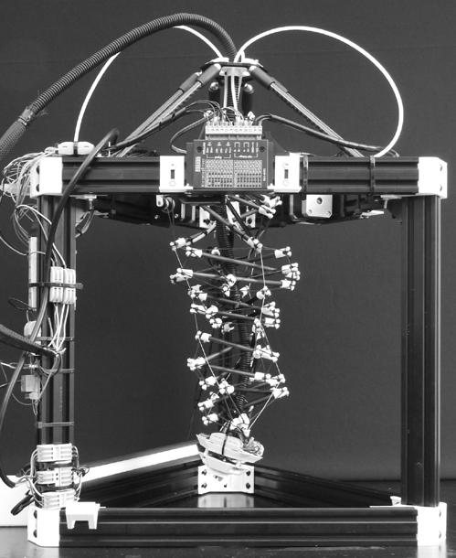
In terms of structural performance, this tensegrity-based form provides high compliance, exibility, control efciency, and effective force distribution with a self-balancing mechanism.
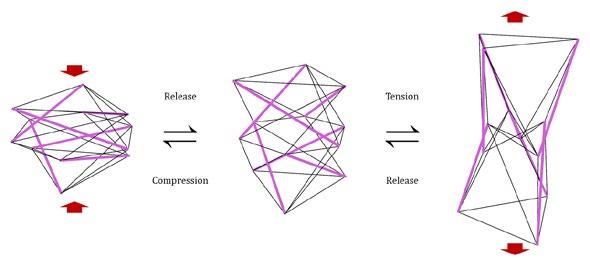
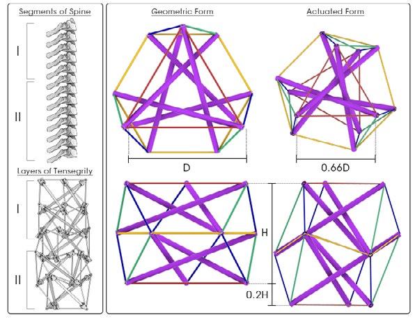
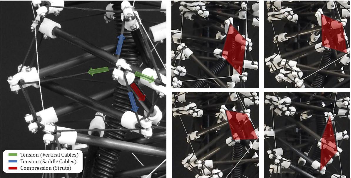
Figure 2. Detail
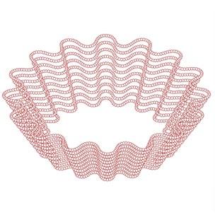
Figure 1. Structural deisgn of the numerical tensegrity structure
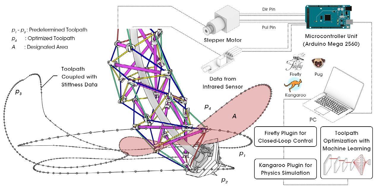
[Kinematic Performance and Potential Application]
The proposed robot exhibited versatility in both multidirectional and unidirectional movements. Plus, the implementation of deep learning allows the robot to gradually achieve biomimetic movements with an ef cient control strategy, especially when navigating through unstructured or undetermined spaces.
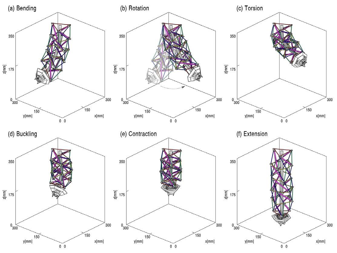
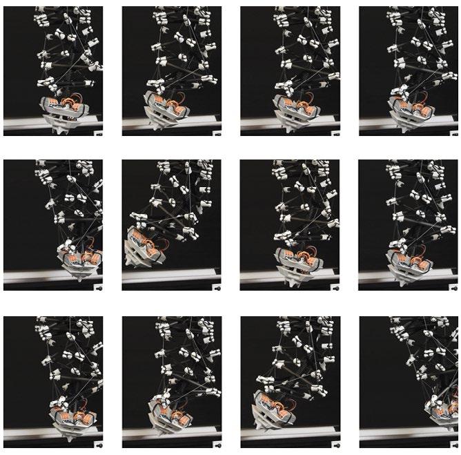
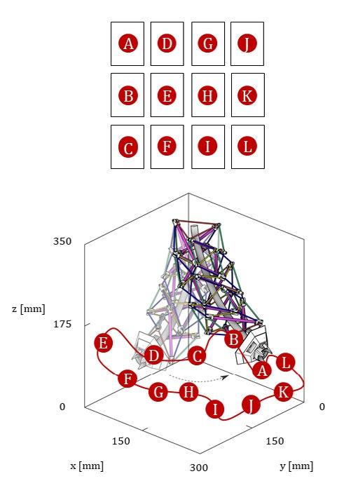
Figure 7. Toolpath
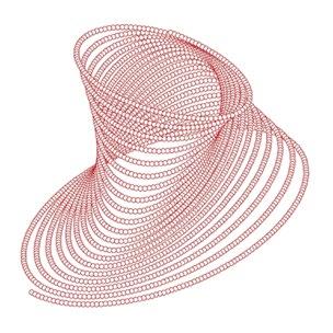
Figure 6. Kinematic performance of the tensegrity-based robot
(a) Bending
(d) Buckling
(b) Rotation
(e) Contraction (c) Torsion
(f) Extension
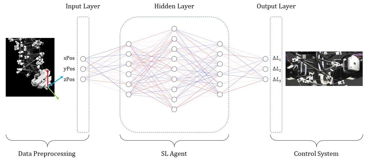
Figure 4. From model-based to model-free control strategy for biomimetic robots
Figure 5. Machine learning for optimal control
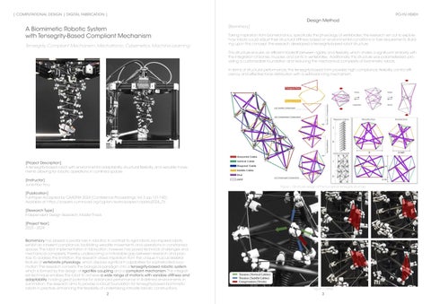
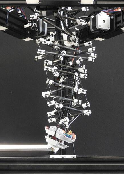
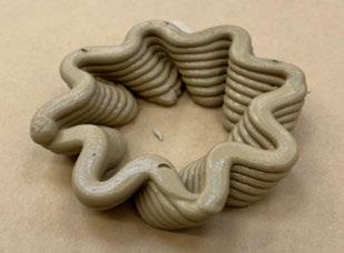
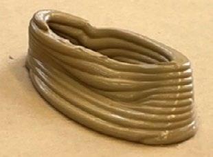
Figure 3. Robot implementation
Research Problem
Comparative Analysis of Learning Models for Bionic Robots
Model-Free Control, Continuum Robot, Learning-Based Method
[Project Description]
This research evaluates machine learning models for optimizing control of bionic robots
[Instructor]
June-Hao Hou
[Publication]
Full-Paper Accepted by ISPACS 2024 (Conference Proceedings)
Available at: https://doi.org/10.48550/arXiv.2407.02428
[Research Type]
Independent Design Research
[Project Year]
2024
The control and modeling of bionic robot dynamics have increasingly adopted model-free control strategies using machine learning methods. Given the non-linear elastic nature of bionic robotic systems, learning-based methods provide reliable alternatives by utilizing numerical data to establish a direct mapping from actuation inputs to robot trajectories without complex kinematics models. However, for developers, the method of identifying an appropriate learning model for their speci c bionic robots and further constructing the transfer function has not been thoroughly discussed. Thus, this research trains four types of models, including ensemble learning models, regularization-based models, kernel-based models, and neural network models, suitable for multi-input multi-output (MIMO) data and non-linear transfer function identi cation, in order to evaluate their (1) accuracy, (2) computation complexity, and (3) performance of capturing biological movements. This research encompasses data collection methods for control inputs and action outputs, selection of machine learning models, comparative analysis of training results, and transfer function identi cations. The main objective is to provide a comprehensive evaluation strategy and framework for the application of model-free control.
[Model-Free Control]
Since the model-free method for the control of bionic robots is a relatively new eld, the method of identifying an appropriate learning model for each speci c robot and constructing transfer functions precisely have not been thoroughly discussed.
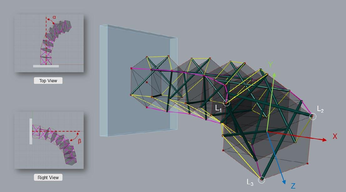
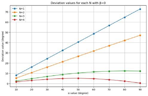
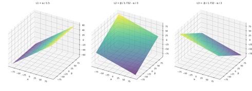
In this case (tensegrity-based continuum robot with fractional order control algorithm), the performance experiment is conducted by inserting a series of target yaw and pitch angles from -90° to 90° at an interval of 10, and collecting the length variation values of each tendon actuator (Figure 1-4). The evaluation of yaw and pitch movements are divided into two seperate processes, which means that the simulation inputs α (pitch angle) and β (yaw angle) are non-zero and zero value alternatively. This allows the vertical and horizontal movements to be clearly viewed seperately. Four conditions with different number of segments (N=1, 2, 3, 4) are selected as the subjects to test out the impact of value N on the actual movements. A noticeable deviation between the actual and desired motions was observed (Figure 5-6). These discrepancies indicate that the original transfer functions are not fully adequate for capturing the non-linear dynamics of the bionic tendon-driven robot. To address this issue, this research explore the use of machine learning models to derive more accurate and robust transfer functions.

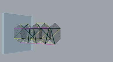
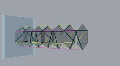
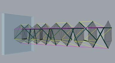
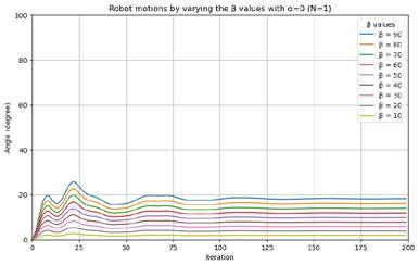
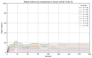
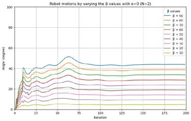
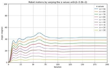
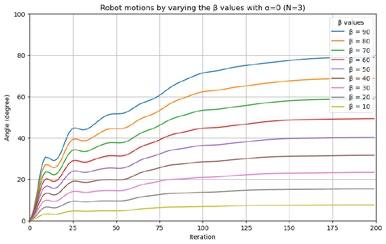
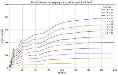
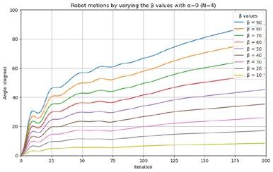
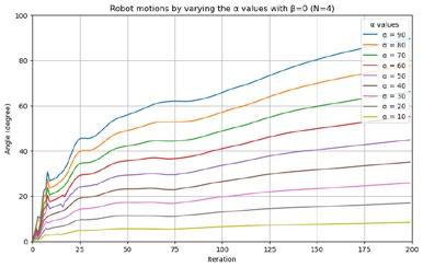
Figure 1. Actual motions with N = 1
Figure 2. Actual motions with N = 1
Figure
Figure 4. Actual motions with N = 1

Method
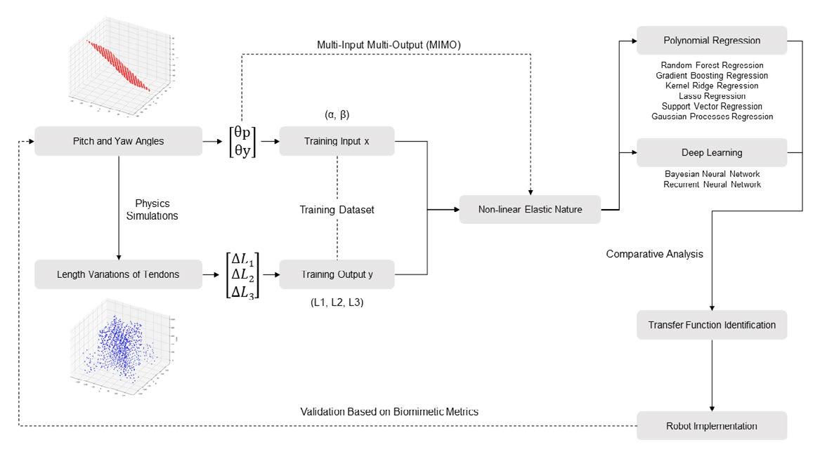
The proposed research methodology is comprised of four principal phases (Figure 7). In the preliminary phase, data collection is conducted using physics simulations to capture robotic motions (yaw and pitch angles) and corresponding actuation parameters (length variations of each tendon). Subsequently, eight different learning models suitable for non-linear data are selected and trained with the dataset. A comparative analysis is then conducted to evaluate the performance of each model, including accuracy and computation costs. Eventually, the transfer functions derived from each learning model are sent back to the robot simulation to validate the actual locomotion based on biomimetic metrics.
[Data Collection]
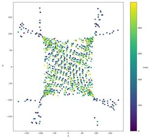
The training dataset for this research was constructed to capture the complex dynamics (in full range of possible motions) of a bionic tendon-driven robot in a multi-input multi-output (MIMO) condition. The data collection process involved simulating various pitch (α) and yaw (β) angles (Figure 8(a)) and recording the corresponding variations in tendon lengths L1, L2, L3 ((Figure 8(b)). To ensure the robustness and generalizability of the training dataset, the input angles were varied systematically, and multiple measurements were taken for each angle combination. This approach ensures that the machine learning models trained on this dataset can generalize well to unseen data, thereby enhancing their predictive performance and reliability.

Experimental Results
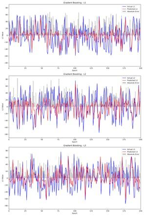
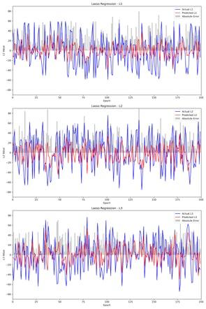
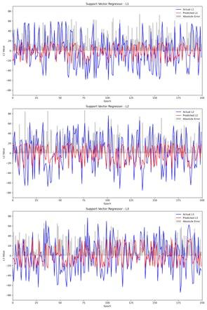
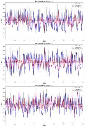
The training process (Figure 9) for each learning model is evaluated by comparing the predicted values (red) against the actual values (blue) for L1, L2, and L3, along with the absolute error (gray) in y-axis. The predictions from gradient boosting model are closely aligned with the actual values, demonstrating the best performance. Table 1 presents an overall performance of each model, including MSE, MAE, and computation time. Despite the lower accuracy, Lasso exhibits noticeably reduced time cost, which is suitable for real-time applications.
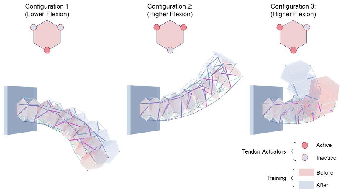
Figure 6. β deviations (with α = 0)
Figure 9. Training results (a) gradient boosting (b) lasso regression (c) support vector (d) recurrent neural network
Figure 11. Robot performance before and after training
Table 1. Performance metrics of different learning models
Figure 7. Methodology
Figure 8. Data collection (a) inputs: pitch and yaw angles (b) outputs: lengths variations of tendon
Figure 5. α deviations (with β = 0)
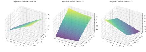
Figure 10. Transfer functions (a) original (b) proposed (a) (b)
A Multi-Media Framework for Continuum Robots: Systematic,
Computational, and Control
Perspectives
Human-Computer Interaction, System Architecture, Dynamics, Control Strategy

[Project Description]
This research presents a system for designing, simulation and control of continuum robots
[Instructor]
June-Hao Hou
[Publication]
Full-Paper Accepted by ISPACS 2024 (Conference Proceedings)
Available at: https://doi.org/10.48550/arXiv.2409.14708
[Research Type]
Independent Design Research
[Project Year]
2024
Continuum robots, which often rely on interdisciplinary and multimedia collaborations, have been increasingly recognized for their potential to revolutionize the eld of human robot interaction (HRI) in varied applications due to their adaptive, responsive, and exible characteristics.
Despite their promises, the lack of an integrated framework poses signi cant challenges for both users and developers, resulting in inef ciency and complexity during preliminary developments. Thus, this paper introduces a uni ed framework for bionic robotics that addresses these challenges by integrating system architecture, dynamics computation, and control strategy. The proposed method allows for ef cient modeling and quick preview of the results in both digital and physical environments, which can enhance the quality of robot developments.
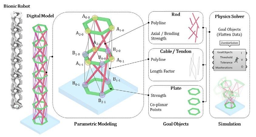
[Dynamics Computation]
The proposed integrates the computational and mechatronic system (Figure 2). In terms of simulation, it uses polyline objects and mesh objects to represent the tendon actuators and rigid components respectively (Figure 2), which reduces the computation complexity and achieves a responsive modeling method. By quickly viewing the simulated dynamics and deformation of continuum robots when applying tensile forces, users can make adjustment to reach their ideal robot con guration or locomotion.

[Control Strategy]
The versatility of continuum robots depends on the manipulation of actuators’ length variations. The simulation results (Figure 1) manipulated by control panel demonstrates the effectiveness of the proposed systematic framework. By inserting the control function (Figure 4), users can easily control the robot’s movement by de ning the ideal yaw and pitch angle (α and β).
Figure 2. System architecture
Figure 4. Computational framework
Figure 1. Control parameter inputs and corresponding performance of digital and physical models
Figure 3. Physics-based simulation
Visualization and Optimization of Continuum Robots: Integration of Lie Group Kinematics and Evolutionary Algorithm
Robot Modeling, Lie Group, Evolutionary Algorithm
[Project Description]
The research introduces an ef cient modeling method for continuum robots
[Instructor]
June-Hao Hou
[Publication]
Published on arXiv: https://doi.org/10.48550/arXiv.2410.14305
Demonstration video: https://youtu.be/9UWLf1npNsw
[Research Type]
Independent Design Research
[Project Year]
2024
Continuum robots, known for their exibility and compliance, offer great potential in applications such as medical surgeries, inspections in con ned spaces, and wearable devices. However, the complexity of their non-linear kinematics and the challenge of achieving effective control and digital modeling hinder their broader adoption. This paper proposes a novel approach to continuum robot modeling by combining Lie group kinematics with an evolutionary algorithm Instead of traditional methods that rely on manual identi cation of modal coef cients, this approach automates the process through an evolutionary optimization mechanism. The proposed method minimizes the deviations between simulated con gurations and ideal shapes, improving ef ciency and accuracy in robot design. Results show the effectiveness of this approach in reducing computational complexity, allowing for real-time modeling and control of continuum robots. This work offers a new perspective on the digital design of soft robotic systems, making them more accessible and adaptable for various applications.
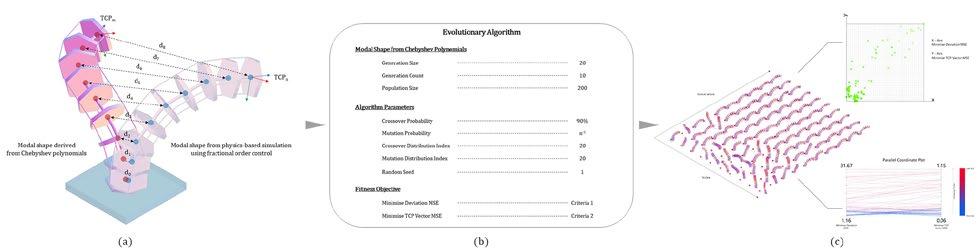
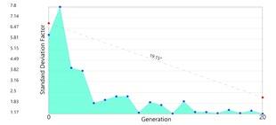
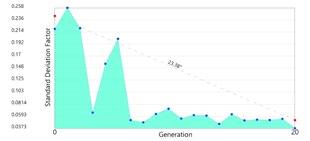
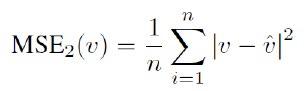
The main concept of the proposed method starts with replacing the traditional modal coef cients identi cation process with an evolutionary algorithm, which is automated and accurate. Firstly, a series of robot con gurations are generated using fractional order control and physics-based simulations in the Grasshopper platform. These con gurations are set as the ideal shapes for the modal shape function s(x). The tness objective of the evolutionary algorithm is to minimize the deviations between the shape derived from the modal shape function and the ideal ones. To achieve this, two tness objectives and settings are de ned as the following:
MSE2 1. Minimize deviation mean squared error

Results
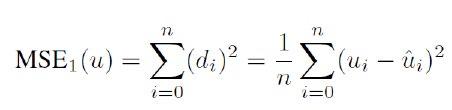
2. Minimize TCP vector mean squared error
• Generation Size: 20
• Generation Count: 10
• Population Size (n): 200
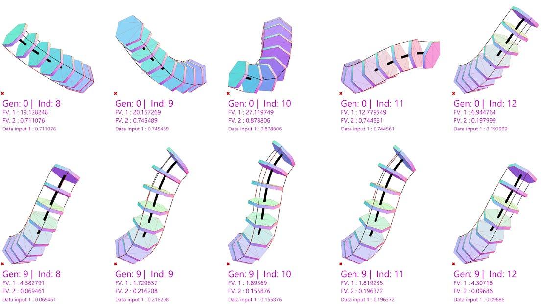
• Crossover Probability: 90%
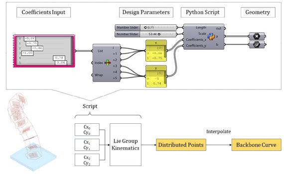
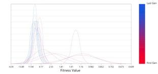
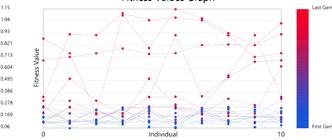
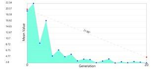
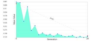
The comparison between Generation 0 (the rst generation) and Generation 9 (the last generation) highlights the effectiveness of the evolutionary algorithm in identifying the modal coef cients, with indexes from 8 to 12 randomly chosen (Figure 1). The individuals from Generation 0 (the rst row) have a lower tness value (FV), demonstrating less similarity to the ideal con guration. The individuals from Generation 9 (the second row), on the other hand, have been re ned by the evolutionary algorithm with an improved FV.
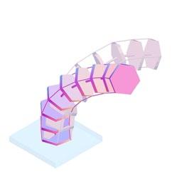

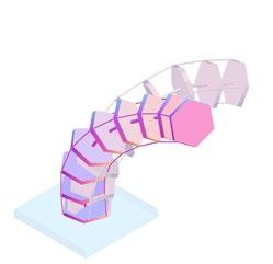
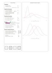
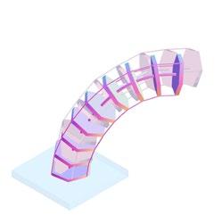
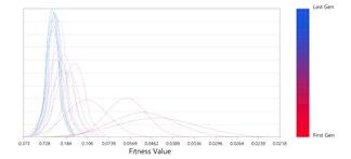
Figure 6. Fitness values trendline
Figure 7. Computational framework
Figure 5. Standard deviation trendline
Figure 3. Standard deviation graph
Figure 4. Fitness values graph
MSE1
Figure 1. Modal shape derived from individual generation
Figure 2. Method (a) input dataset (b) evolutionary algorithm (c) generated continuum robot model
Figure 8. Optimization process over three stages
color: target
(c) (b) (a)
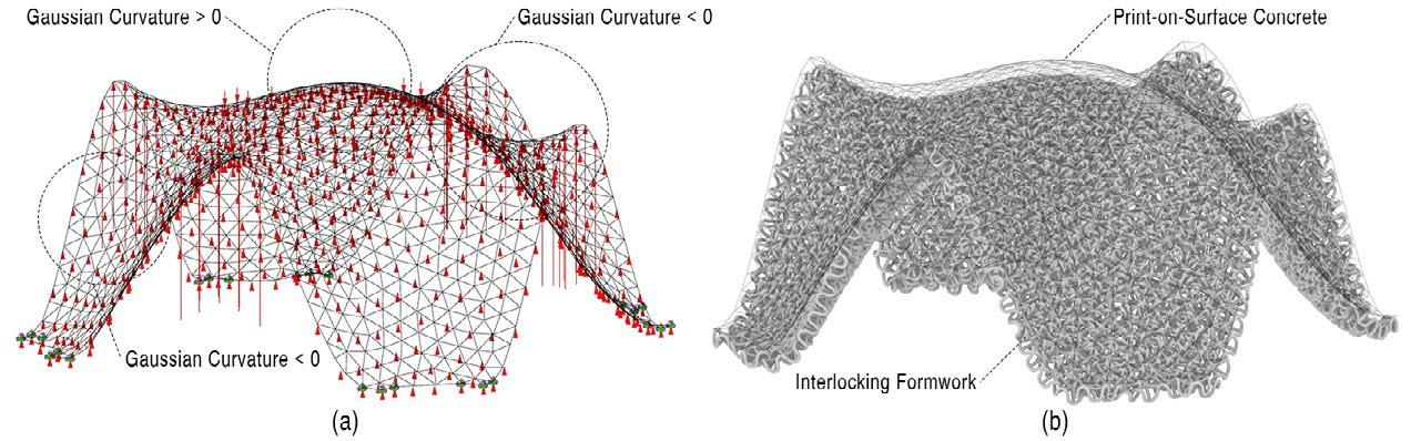
Discrete Interlocking Formwork: A Computational Solution to Non-Developable Surfaces
Structural Design, Computational Design, Tessellation, Fabrication Solution

[Project Description]
An adjustable formwork system based on discrete interlocking mechanism of chainmail, which is suitable for 3DCP complex geometries with non-developable surfaces
[Instructor]
June-Hao Hou
[Publication]
Full-Paper Accepted by eCAADe 2024 (Conference Proceedings, Vol.1, pp.333-342) Available at: https://papers.cumincad.org/cgi-bin/works/paper/ecaade2024_87
[Research Type]
Independent Design Research
[Project Year] 2023 - 2024
Shotcrete 3D concrete printing (SC3DCP) technology offers vast potential for digital fabrication and structural engineering. However, it faces limitations with complex geometries involving non-developable surfaces. To address these technical challenges from a computational perspective, this research introduces an adjustable formwork system based on a discrete interlocking mechanism. The proposed model consists of an octagonal, porous unit inspired by chainmail. By utilizing the unique chainmail pattern and interlocking parts, the proposed form ensures: (1) a wide range of exibility at each node that can be applied to various types of curved surfaces; (2) can be reused overtime by adjusting each interlocking part; (3) print-in-place capability without external supports, reducing assembly complexity compared to traditional engineered formwork systems. Overall, the research aims to reduce geometric constraints in the construction domain through a novel, practical method.
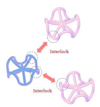

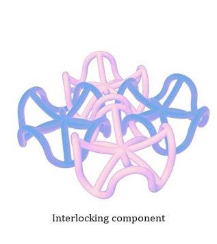
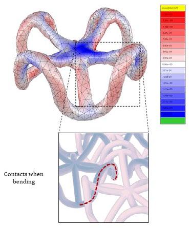
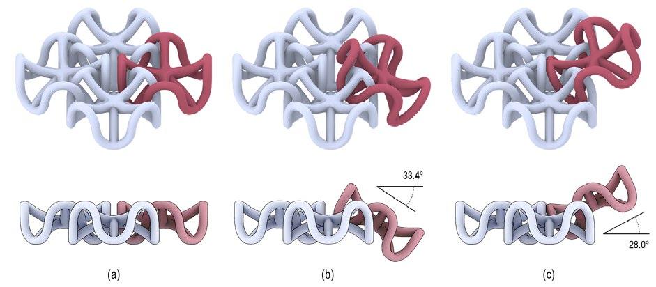
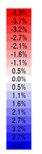

Figure 4. Range of movement in isometric view (top) and elevation (bottom)
Figure 7. Results (a) nal con guration (b) utilization of load-bearing capacity (c) bending moment distribution (a) (b) (c)
Figure 6. Grafting on varied surfaces
Figure 5. Tessellation method
Figure 2. Proposed interlocking mechanism
Figure 3. FEM analysis
Figure 1. From mesh face analytics to discrete tessellation
Low-Tech Bamboo Constructions: A Cable-Strut Approach for Resource-Limited Conditions
Design-Build, Tectonic, Flexible Connection, Construction, Bamboo Structure

[Project Description]
A reciprocal bamboo structure based on cable-strut connection, integrating design computation and construction
[Instructor]
June-Hao Hou, Pei-Hsien Hsu
[Publication]
Full-Paper Accepted by eCAADe 2024 (Conference Proceedings Vol.1, pp.393-400) Available at: https://papers.cumincad.org/cgi-bin/works/paper/ecaade2024_115
[Research Type]
Collective Design Research, Design-Build Project
[Project Year] 2023
Despite the rapid development of building technologies, low-tech construction methods using local materials are still preferred in resource-limited areas. The question addressed in this research is how design computations can be integrated into a localized building process. This research is conducted in collaboration with an architectural practice at the NYCU campus in Hsinchu, an area rich in bamboo resources. Given the contextual challenges of limited time and technical expertise, the research aims to develop a low-tech, tectonic framework for bamboo structures, which includes (1) form- nding iterations combining reciprocal frame and tensegrity structures, (2) an advanced cable-strut connection approach utilizing local resources and the inherent exibility of bamboo culms, (3) a decoupled assembly process enhanced by computational tools, and (4) practical application in the nal project.

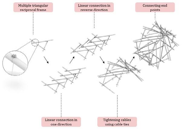
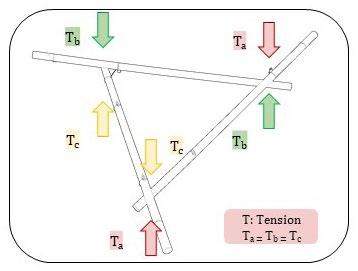
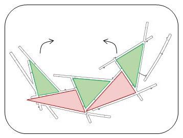
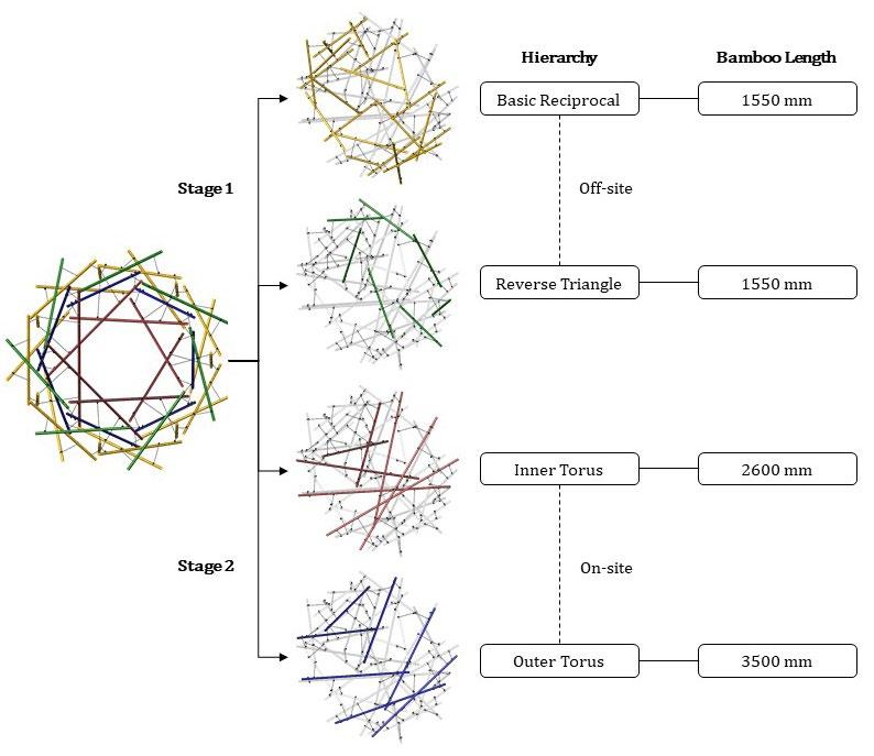

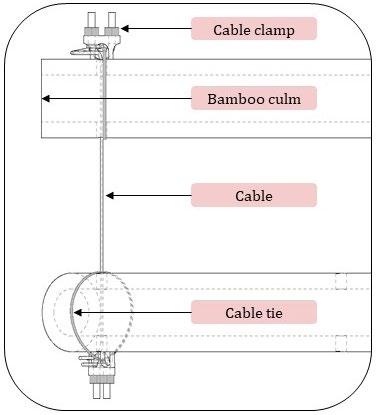
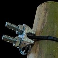
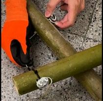
Figure 3. (a) Basic reciprocal frame (b) belt shape foundation
Figure 4. Hierarchy of the structure
Figure 1. Form- nding
Figure 2. Simulated construction process
Figure 5. (a) Cable-strut connection (b) free body diagram (c) detail drawing (d) detail
(a)
(b)
Fabrication Process Overview
Robotic 3D-Printed Ceramics: Merging Crafts with Digital Fabrication
3D-Printing, Ceramics, Robotics, Toolpath, Digital Fabrication
[Project Description]
An practical exploration of 3D-Printed ceramics with robotic arm, including mechanical design of clay material extrusion, toolpath optimization, and ceramics processing
[Instructor]
Shih-Yuan Wang
[Collaboration]
Hsin Chen, Yi-Ting Lo, Glazeshome
[Research Type]
Collective Design Research and Implementation
[Project Year]
2023 - 2024
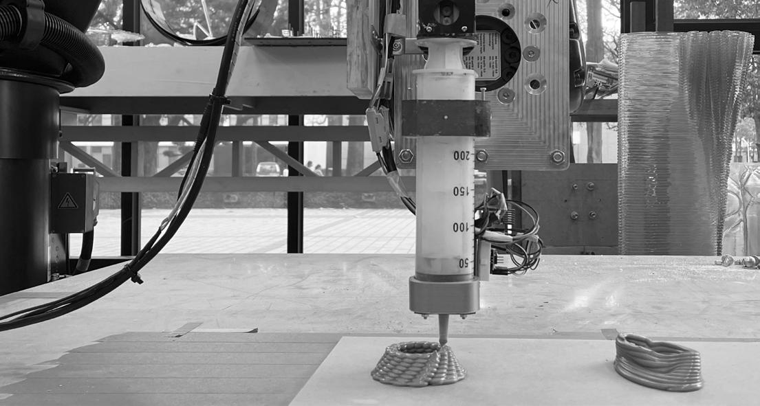
3D-Printing techniques using robotic arm have been gradually applied in current digital fabrication domain. With the robotic manipulation, the manufacturing quality can be precisely controlled. While most 3D-Printing practice often utilize traditional building materials such as concrete, this project aims to explore the potential of clay material extrusion. The design research includes mechanical design of end effector, toolpath computation material experiment, and nal ceramics processing, with a speci c focus on design-to-fabrication work ow for small-scale 3D-Printed ceramics. The entire trial and error process eventually provides a robust hardware and software settings, which can be further applied to other clay-based project or related 3D-Printing research.
Mechanical Design
Toolpath Experiment
Rotation Expansion Gradient Ellipse Radius with Perlin Noise
Linear Slide Rail
Figure 1.
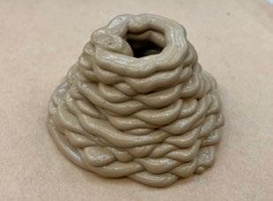
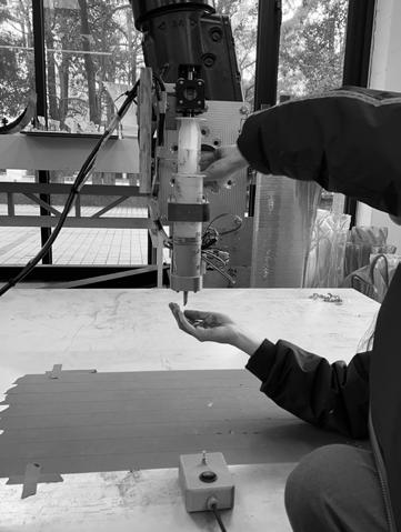
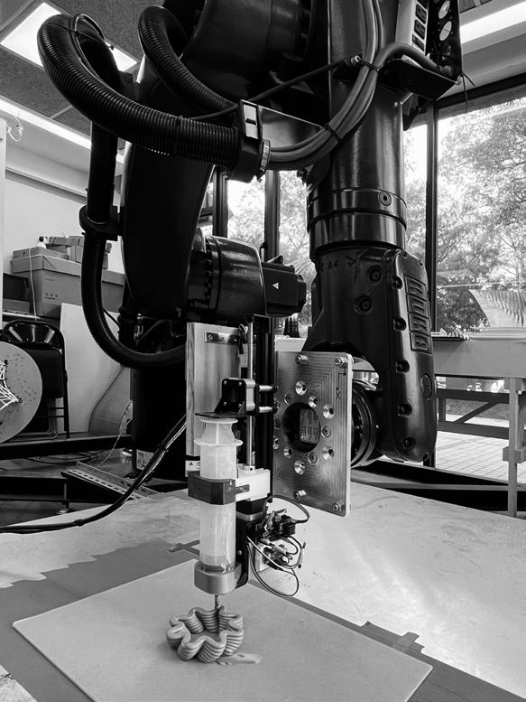
3D-Printed ceramics approach (a) wedging (b) 3D-Printing using robotic arm (c) glaze and ring
Figure 2.
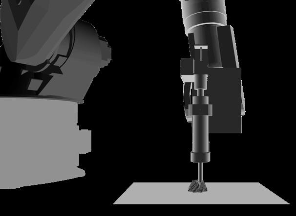
Robotic setup
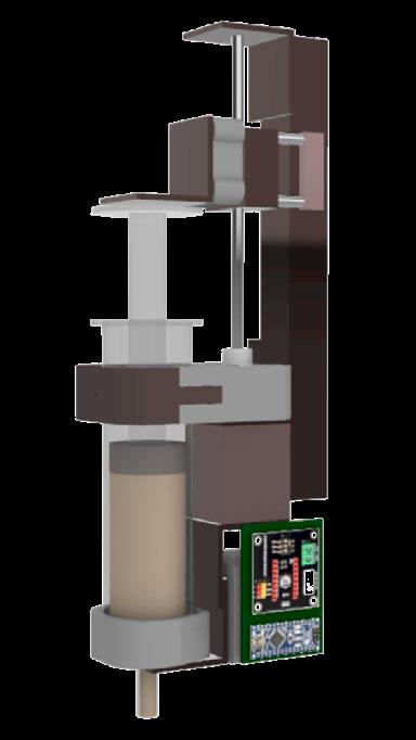
(a) robotic arm (b) end effector designed for clay material extrusion
Stepper Motor
Syringe Motor Controller Clay
(a)
(a)
(b) (b) (c)
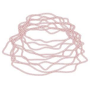
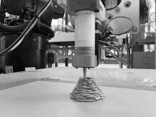
Figure 3. Computational design (top) and 3D-printing result (bottom)


Ceramics Processing
[Implementation]
Experimental Result
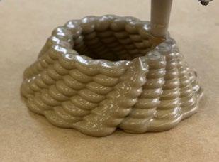
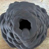
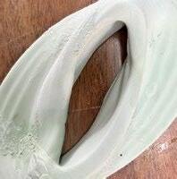
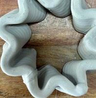
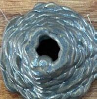
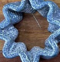
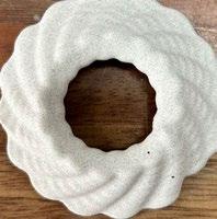
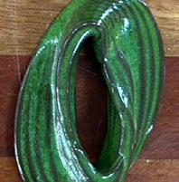
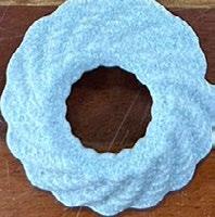
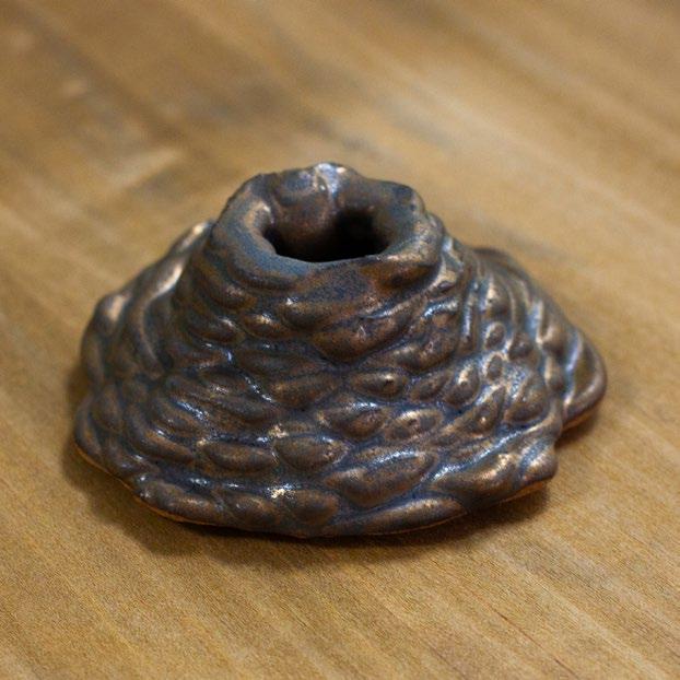
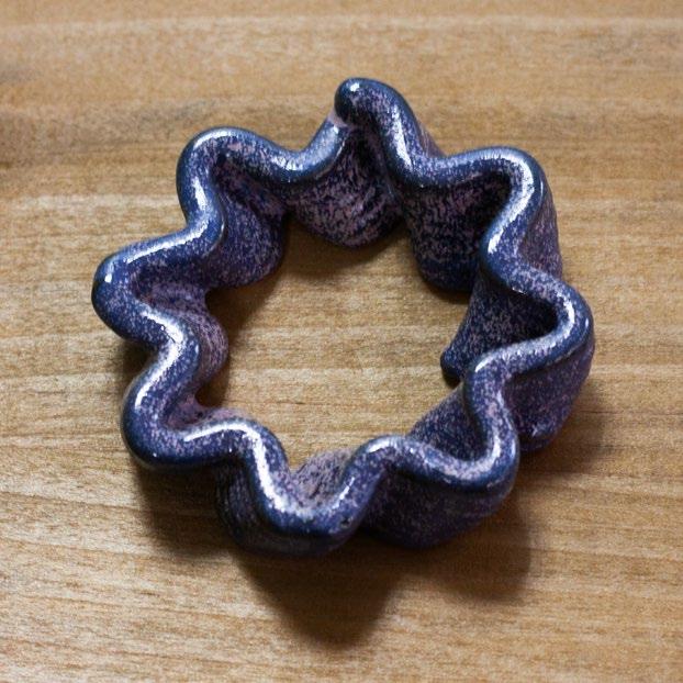
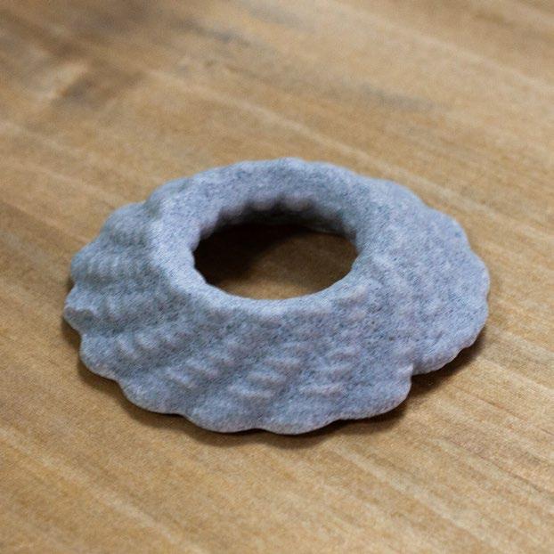
Four types of toolpath for clay material extrusion were applied in this research, including rotation, expansion, gradient ellipse, and randomized radius. The expansion case demonstrated the best quality during 3D-Printing and after ceramics processing. The rotation and randomized radius case both showed a certain amount of shrinkage after ceramics processing, which might result from an irresistable thermal or humidity instability. The gradient ellipse case suffered from collapse during 3D-Printing process, which might be related to the exceeding overhang toolpath.

Bisque Firing (700-900 °C) Glaze
Glaze Firing (1200 °C)
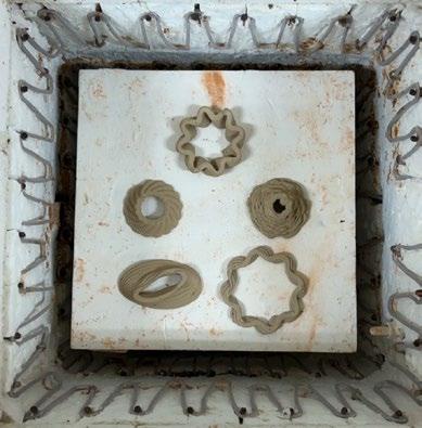
Figure 6. Detailed photo of ceramics processing after 3D-printing
Figure 5. Exploration of material and form
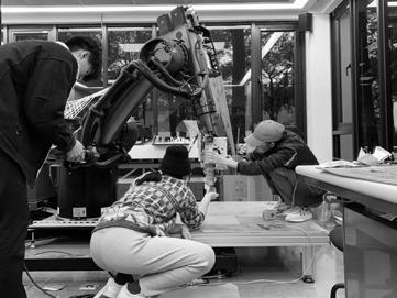
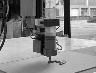
Figure 4. From computation to robotic operation (a) end effector installation (b) trial and error process (c) nal result
Figure 7. Final production
(a)
(c)
(b)