Volume XXXVI - Issue I - March.,2026

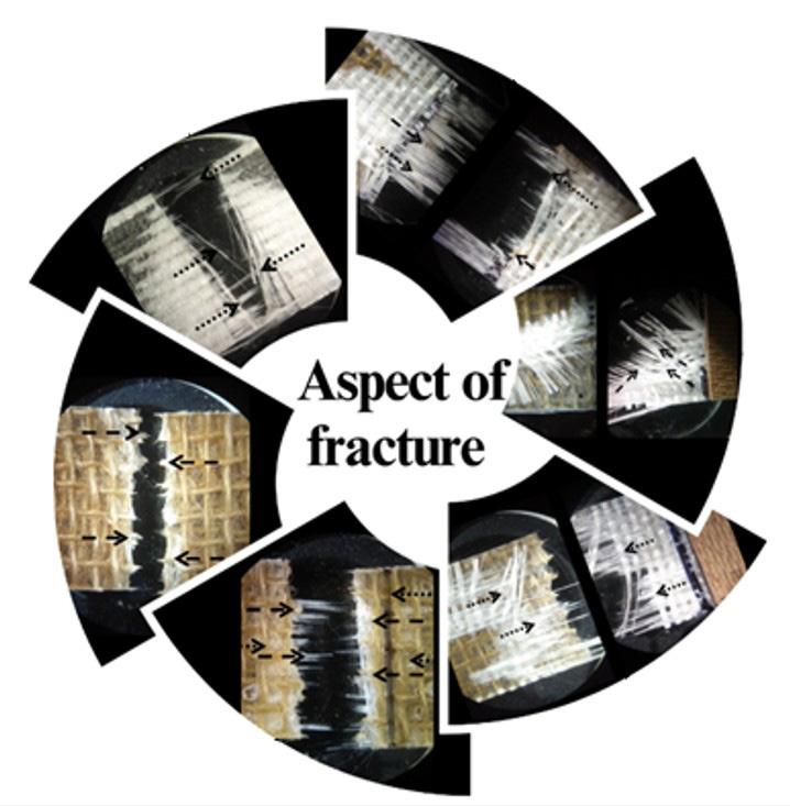
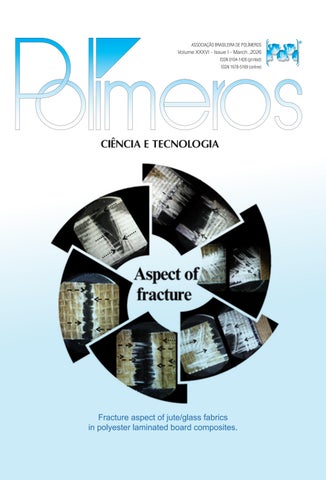
Fracture aspect of jute/glass fabrics in polyester laminated board composites.
e d I tor I al C ou NCI l
Volume XXXVI - Issue I - March.,2026
Fracture aspect of jute/glass fabrics in polyester laminated board composites.
e d I tor I al C ou NCI l
Edvani Curti Muniz (UFPI/DQUI; UEM/DQI)- President
m ember S
Alain Dufresne (Grenoble INP/Pagora)
Ana V. A. Machado Nóbrega (UMinho/DEP)
Antonio Aprigio S. Curvelo (USP/IQSC)
Artur José Monteiro Valente (UC/DQ)
Bluma G. Soares (UFRJ/IMA)
César Liberato Petzhold (UFRGS/IQ)
Cristina T. Andrade (UFRJ/IQ)
Daniela Becker (UDESC/DEM)
Denise F. S. Petri (USP/IQ)
Edson R. Simielli (Simielli - Soluções em Polímeros)
Elias Hage Jr. (Retired – UFSCar/DEMa)
Janaina S. Crespo (UCS/DEFQ)
José Alexandrino de Sousa (Retired – UFSCar/DEMa)
José António C. Gomes Covas (UMinho/IPC)
José Carlos C. S. Pinto (UFRJ/COPPE)
Júlio Harada (Harada Hajime Machado Consutoria Ltda)
Luiz Antonio Pessan (UFSCar/DEMa)
Luiz Henrique C. Mattoso (EMBRAPA)
Marco Aurelio De Paoli (UNICAMP/IQ)
María del Mar Orta Cuevas (US/QA)
Nikos Hadjikristidis (KAUST/ PSE)
Paula Moldenaers (KU Leuven/CIT)
Roberto Pantani, (UNISA/DIIn)
Rodrigo Lambert Oréfice (UFMG/DEMET)
Sandra A. Cruz (UFSCar/DQ)
Sebastião V. Canevarolo Jr. (Retired – UFSCar/DEMa)
Silvio Manrich (Retired – UFSCar/DEMa) You-Lo Hsieh (UC Davis/BAE)
Financial support:
e d I tor I al C omm I ttee
Sebastião V. Canevarolo Jr. – Editor-in-Chief a SS o CI ate e d I tor S
Alain Dufresne
Artur José Monteiro Valente
Bluma G. Soares
César Liberato Petzhold
José António C. Gomes Covas
José Carlos C. S. Pinto
Marcelo Silveira Rabello
Paula Moldenaers
Richard G. Weiss (in memoriam)
Roberto Pantani
Rodrigo Lambert Oréfice
d e S kto P P ubl IS h IN g
www.editoracubo.com.br
“Polímeros” is a publication of the Associação Brasileira de Polímeros
São Paulo 994 St. São Carlos, SP, Brazil, 13560-340
Phone: +55 16 3374-3949
emails: abpol@abpol.org.br / revista@abpol.org.br http://www.abpol.org.br
Date of publication: March 2026

Available online at: www.scielo.br

Polímeros / Associação Brasileira de Polímeros. vol. 1, nº 1 (1991) -.-
São Carlos: ABPol, 1991-
Quarterly
v. 36, nº 1 (March 2026)
ISSN 0104-1428
ISSN 1678-5169 (electronic version)
1. Polímeros. l. Associação Brasileira de Polímeros.
Website of the “Polímeros”: www.revistapolimeros.org.br
r e VI ew a rt IC le
Fibrous scaffolds for tissue engineering: from conceptualization to implementation
Thais Sayuri Iguma, Vitor Andrade Nascimento, Luciana Pastena Giorno, Sônia Maria Malmonge and Arnaldo Rodrigues Santos Jr. e20260006
A review of non-destructive testing for polymeric composites: techniques, challenges, and advances
Ingrid Regina dos Santos Lacerda, Michelle Leali Costa and Mirabel Cerqueira Rezende
o r I g IN al a rt IC le
Sustainable bioplastics based on shrimp chitin: mechanical characterization and biodegradability evaluation
Jorge Braulio Amaya and Paola Duque Sarango
Comparative analysis of nitride and oxide based nano fillers for polypropylene insulation
Sundaramahalingam Subramaniam and Manikandan Bairavan Veerayan
Development of active LDPE packaging with antioxidants from agro-industrial wine waste
Vanessa Machado Babinski Ramos, Eliseu Rodrigues and Ruth Marlene Campomanes Santana
Mechanical performance of biobased polyurethane composites reinforced with treated sisal fibers
e20260007
e20260001
e20260002
e20260003
Bruno Targino de Oliveira, Renata Martins Parreira e20260004
Surface properties of stainless steel coated with plasma-modified gelatin films
Shih-Hang Chang and Chun-Yi Tseng e20260005
Enhanced thermal and transport properties of PP/CaCO3 micro- and nanocomposites: performance evaluation
Juliano Martins Barbosa,, Renato Meneghetti Peres, Bruno Milton Oliveira Silva, Ricardo Jorge Espanhol Andrade, and Hélio Ribeiro
Bio-based hydrogel fertilizer from h-collagen-g-PAA for water retention and urea management
Febriani Purba, Ono Suparno, Meika Syahbana Rusli and Is Fatimah
Cotton textile with citronella nanoparticles: antimicrobial properties and surface functionalization strategies
e20260008
e20260009
Mariele Paludetto Sanches, Rodrigo Henrique Saatkamp, Idejan Padilha Gross, Taís Felix, Nito Angelo Debacher, Markus Wilimzig, Alexandre Luis Parize and Valdir Soldi e20260010
Exploring urea and cross-linkers in alginate films for agricultural seedlings
Nivaldo Ramos Júnior, Ana Paula Testa Pezzin and Denise Abatti Kasper Silva e20260011
Mechanical performance of laminated boards using polyester with jute and glass fabrics
Jair Francisco Souza Magalhães, Larissa dos Santos Borges, Roberto Yuri Costa Dias, Jerson Rogério Pinheiro Vaz and Roberto Tetsuo Fujiyama e20260012
Sebastião V. Canevarolo1*
1 Editor-in-Chief, Canevarolo Assessoria Industrial Ltda, São Carlos, SP, Brasil *caneva@ufscar.br
Recently we have heard the sad news of Prof. UT, as he was kindly called by everyone, has passed away. He was a value member of the Department of Chemical and Petroleum Engineering at Schulich in Calgary, Alberta, Canada. He did an undergraduate course of Chemical Engineering at University of Alberta, Canada and got his Ph.D. in 1996 from University of Minnesota, EUA. From 2000 to 2009 he was a Professor at University of Alberta, Canada and since then as a Professor and Schulich Industry Research Chair at University of Calgary, Canada.
He has published over 380 refereed publications, with more than 19.000 citations (ResearchGate). The most cited ones are listed below. Holds multiple patents and was among the top 1% of researchers in his field.
He received several prestigious awards like, Macromolecular Science and Engineering Award, Inducted into Canadian Academy of Engineering, Fellow of Society of Plastics Engineers, Fellow of Chemical Institute of Canada. He was the winner of the Morand Lambla Award in 2003, the conference chair of PPS 26 in 2010 in Banff, Canada, and supported the Polymer Processing Society as chair of the PPS Award Committee, a scientific community he has been involved in since his early carrier research.
He was not only an exceptional scientist, but also an excellent teacher receiving numerous recognitions such as Schulich Award for Excellence in Graduate Supervision, Teaching Leadership Award, Students’ Union Teaching Excellence Award. Many of his students have described UT as much more than a supervisor, as being engaged with them as human beings, and felt like a father to them.
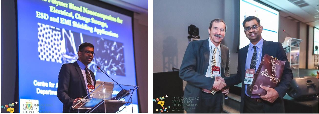
He participated in 5 editions of the Congresso Brasileiro de Polímeros CBPol (2011, 2013, 2015, 2019, 2025) and in the Simpósio Latino-Americano de Polímeros SLAP (2014), giving 2 plenary lectures and 6 oral contributions.
Beyond his professional achievements, he will always be remembered by his care with his family, wife Suzy, daughter, Arielle, son, Ethan, his mother, brothers and many relatives. He will be remembered for his kindness, generosity, and willingness to share his knowledge, a true source of inspiration, leaving an indelible mark on everyone who had the privilege to know and work with him.
We leave our sincere condolences to his family and loved ones.
With my deepest sympathy,
References
Sebastião V. Canevarolo Editor-in-Chief, Polímeros
Big returns from small fibers: A review of polymer/carbon nanotube composites, Polymer Composites, 25(6), 630-645, 2004. https:// doi.org/10.1002/pc.20058. # citations: 1774.
Electromagnetic interference shielding mechanisms of CNT/polymer composites, Carbon, 47(7), 1738-1746, 2009. https://doi. org/10.1016/j.carbon.2009.02.030. # citations: 1724
A review of vapor grown carbon nanofiber/polymer conductive composites, Carbon, 47(1), 2-22, 2009, ttps://doi.org/10.1016/j. carbon.2008.09.039. # citations: 1349.
Drop Breakup and Coalescence in Polymer Blends: The Effects of Concentration and Compatibilization, Macromolecules, 28(8), 2647–2657, 1995, https://doi.org/10.1021/ma00112a009. # citations: 1129.
EMI shielding effectiveness of carbon based nanostructured polymeric materials: A comparative study, Carbon, 60, 146-156, 2013, https://doi.org/10.1016/j.carbon.2013.04.008. # citations: 984.
A South Korean research team has developed a nextgeneration lithium-metal battery technology that could double the driving range of electric vehicles. The Gwangju Institute of Science and Technology (GIST) announced on the 1st that a research team led by Professor KwangSup Eom, Director of the Advanced Energy Research Institute, has solved previous performance degradation issues by designing a new three-dimensional lithiummetal battery structure. The research findings were published online in the international journal ‘Energy & Environmental Materials’ on the 29th of last month.
Lithium-ion batteries, currently used in most electric vehicles, offer high energy storage for their size and weight, but further performance improvements are difficult. Lithium-metal batteries, a promising alternative, can theoretically store twice as much energy. However, repeated charging and discharging causes lithium to deposit unevenly, forming sharp, tree-like structures called dendrites that damage the battery’s interior and shorten its lifespan. The research team redesigned the battery’s structure to ensure lithium deposits uniformly from the inside out. They used PVDF, a lightweight and durable polymer, to create more internal void space for lithium. They also coated the surface with polypyrrole, a polymer with low electrical conductivity, to prevent lithium from accumulating on the surface. As a result, the lithium deposited evenly from the interior, significantly reducing issues with dendrite formation and volume expansion.
The new lithium-metal battery demonstrated an energy storage density more than twice that of conventional lithium-ion batteries. It could be fully charged in about 12 minutes and operated stably even during high-speed charging. After 200 charge-discharge cycles, it retained 94.7% of its initial capacity with no volume expansion. The team stated that the solution-based coating process allows for large-scale production, enabling commercialization in various fields such as electric vehicle batteries, energy storage systems, and aerial mobility.
Professor Kwang-Sup Eom expressed his expectations, stating, “We have solved a chronic problem of lithiummetal batteries. Commercialization could more than double the range of electric vehicles and aerial mobility, and also enable ultra-fast charging.”
Source: DongA Science – www.dongascience.com
UC Berkeley professor Ting Xu has spent more than seven years trying to figure out how to design synthetic polymers with protein-like behaviors. Now, she and a team of researchers have unlocked “design rules” that upend long-held views on polymers and could pave the way for eco-friendly plastics and other materials.
As reported recently in Nature, the researchers, including MIT professor Alfredo Alexander-Katz, discovered something “wild” when they set out to design polymers as synthetic enzymes: Though their synthetic enzyme couldn’t fold like a natural protein, and its underlying molecular structure was slightly different, it could still mimic the behavior of a natural enzyme. According to Xu, professor of materials science and engineering and of chemistry, the key lies in the polymer’s ability to bend, twist and easily change the shape of its carbon “backbone.” This flexibility not only compensated for any structural differences between the lab-created and natural versions, but it also enabled the synthetic enzyme to surpass the functional capabilities of a natural enzyme.
“This work is philosophically a quantum leap for us,” said Xu, who is also a faculty scientist at Lawrence Berkeley National Laboratory. “I went from thinking that I won’t be able to replicate the function of the proteins until I can replicate their exact structure and monomeric sequencing, to now seeing a viable pathway. It fundamentally shifts my view on how we should design bioinspired materials.” A highly collaborative effort, this investigation brought together researchers from UC Berkeley; MIT; University of Illinois UrbanaChampaign; University of California, Davis; and University of Michigan.
According to Xu, identifying these design rules could lay the groundwork for future research and applications. “This foundational knowledge will enable us to produce functional polymers that meet technological needs in a range of areas, from the life sciences and energy to the environment,” she said. One long-range goal is to use this knowledge to “re-imagine the plastics industry” and solve the ongoing compatibility issues between our need for plastics and their environmental impact. “If we design the polymer right, we may be able to develop plastics that meet both our current durability requirements and future environmental goals,” she said. Xu added that understanding this translation mechanism will also enable the design of new materials that can do things that natural enzymes can’t — like safely break down antibiotics that pollute our waterways.
“This work is the culmination of many years of research,” she said. “It shows the importance of basic science and how it can open the door to exciting possibilities.”
Source: UC Berkeley Engineering – engineering.berkeley.edu
D AAApril
Inscitech Meet on Polymer Science and Composite Materials (IMPOLYMER2026)
Date: April 20-22, 2026
Location: Rome, Italy
Website: inscitechsummits.com/2026/polymer-science
May
Fire & Polymers 2026
Date: May 17-20, 2026
Location: San Diego, California, United States of America
Website: polyacs.org/2026fireandpolymers
Polymer Sourcing and Distribution
Date: May 19-21, 2026
Location: Hamburg, Germany
Website:ami-events.com/event/aa711e6d-2de5-4e11-82ba97fdd7d4e05b
World’s Leading Conference on Polymer Science & Composite Materials (Polymer Summit 2026)
Date: May 29-30, 2026
Location: Berlin, Germany
Website: polyscienceconference.com
41st International Conference of the Polymer Processing Society (PPS-41)
Date: May 31-June 4, 2026
Location: Salerno, Italy
Website: pps-41.org
June
Bordeaux Polymer Conference (BPC 2026)
Date: June 1-4, 2026
Location: Bordeaux, France
Website: bpc2026.u-bordeaux.fr/en
Eighth International Symposium Frontiers in Polymer Science
Date: June 11-14, 2026
Location: Chengdu, China
Website: elsevier.com/events/conferences/all/frontiers-in-polymerscience
87th Prague Meeting on Macromolecules Smart Materials: Self-Organizing Polymers at the Interface of Technology and Nature (PMM 87 Smart Materials)
Date: June 21-25, 2026
Location: Prague, Czech Republic
Website: imc.cas.cz/sympo/87pmm
6th Global Conference on Polymers, Plastics & Composites (PPC-2026)
Date: June 24-25, 2026
Location: Barcelona, Spain (hybrid)
Website: polymers-plastics.org
World Summit and Expo on Polymers and Composite Materials (WSEPCM-2026)
Date: June 24-25, 2026
Location: Warsaw, Poland
Website: polymers2026.scientificsummits.org
Polymers 2026: Trends, Innovation and Future
Date: June 25-28, 2026
Location: Nanjing, China
Website: sciforum.net/event/polymers2026
Polymer Engineering and Sciences International (PESI 2026)
Date: June 28-July 2, 2026
Location: Kanazawa, Japan
Website: polymers-int.org
July
Polymers and Footwear Innovations
Date: July 22-23, 2026
Location: Portland, Oregon, United States of America
Website: ami-events.com/event/749a47b2-12dd-4e1d-a1090febf35491e5
9th International Congress on Advanced Materials Sciences and Engineering 2026 (AMSE-2026)
Date: July 22-24, 2026
Location: Zagreb, Croatia
Website: istci.org/amse2026/index.asp
4th International Summit on Biopolymers and Polymer Science (ISBPS2026)
Date: July 23-25, 2026
Location: Prague, Czech Republic
Website: polymerscience2026.spectrumconferences.com
15th World Congress on Biopolymers and Biomaterials
Date: July 27-28, 2026
Location: Paris, France
Website: biopolymerscongress.conferenceseries.com
51st IUPAC World Polymer Congress (MACRO 2026)
Date: July 28-31, 2026
Location: Sarawak, Malaysia
Website: macro2026.org
August
12th International Conference on Chemical and Polymer Engineering (ICCPE 2026)
Date: August 18-20, 2026
Location: London, United Kingdom Website: cpeconference.com
3rd Edition Global Summit on Polymer Science & Composite Materials
Date: August 24-25, 2026
Location: Paris, France
Website: globalpolysciencesummit.com
Global Summit on Sustainable Biopolymers and Polymer Applications (POLYMERS2026)
Date: August 26-27, 2026
Location: Venice, Italy
Website: biopolymers.researchconnects.org
September Bioplastics
Date: September 1-2, 2026
Location: Cleveland, Ohio, United States of America
Website: ami-events.com/event/a57ba0e7-de68-4cf6-b4c58c0955be8ef5
Annual Global Summit on Polymers and Composite Materials (AGSPOLYMERS2026)
Date: September 21-23, 2026
Location: Prague, Czech Republic
Website: vividglobalsummits.com/2026/composite-materials
International Conference on Next Horizons in Polymers: Beyond the past 50, toward the next 100 (IUPAC-PSK50)
Date: September 28-October 1, 2026
Location: Busan, South Korea
Website: polymer.or.kr/conferenceintl/default
October
5th International Conference on Polymer Science and Engineering
Date: October 7-9, 2026
Location: San Francisco, California, United States of America Website: polymers.unitedscientificgroup.org
6th International Conference on Polymer Science & Composite Materials (ISTDPCM 2026)
Date: October 7-9, 2026
Location: Dubai, United Arab Emirates
Website: inovscitechconferences.com/2026/dubai/polymerscience
XIX Latin American Symposium on Polymers and XVII Ibero-American Congress on Polymers - SLAP 2026
Date: October 19-23, 2026
Location: Salvador, Bahia, Brazil Website: slap2026.com.br
November
Fire Resistance in Plastics
Date: November 3-4, 2026
Location: Düsseldorf, Germany
Website: ami-events.com/event/097c9771-7499-4a0c-9bb0d857a4ea771f
International Connect & Expo on Biopolymers and Polymer Science (POLYMERCONNECT2026)
Date: November 26-28, 2026
Location: Paris, France Website: polymerscience.theinfiniteminds.net

























Thais Sayuri Iguma1 , Vitor Andrade Nascimento1 , Luciana Pastena Giorno1 , Sônia Maria Malmonge2 and Arnaldo Rodrigues Santos Jr.1*
1Laboratório de Sistemas Biológicos e Genômica, Centro de Ciências Naturais e Humanas, Universidade Federal do ABC – UFABC, São Bernardo do Campo, SP, Brasil
2Laboratório de Pesquisa em Biomateriais e Engenharia de Tecidos, Centro de Engenharia, Modelagem e Ciências Sociais Aplicadas, Universidade Federal do ABC – UFABC, São Bernardo do Campo, SP, Brasil
*arnaldo.santos@ufabc.edu.br
Rbstract
To reduce reliance on transplants in cases of disease or trauma caused by accidents, biotechnologies in regenerative medicine and tissue engineering have emerged. The primary goal of tissue engineering is to fabricate devices that mimic the extracellular matrix of injured tissues, thereby facilitating their repair. The synthetic polymer poly(ε-caprolactone) (PCL) is recognized for its favorable mechanical properties, including load-bearing capacity, biocompatibility, and controllable biodegradability. Gelatin, derived from collagen, can replicate the natural extracellular matrix and is rich in amino acids that promote cell adhesion, proliferation, and differentiation, all of which contribute to tissue repair. This study aims to review the fabrication of fibrous scaffolds for tissue engineering, covering process from biomaterial conception to production and application. Conceptual challenges are discussed using gelatin as an example of a natural polymer and PCL as an example of a synthetic polymer.
Keywords: biotechnology, gelatin, poly (ε-caprolactone), regenerative medicine, spinning techniques.
Data Rvailability: All data supporting the findings of this study are included in this article and its supplementary materials.
How to cite: Iguma, T. S., Nascimento, V. A., Giorno, L. P., Malmonge, S. M., & Santos Jr., A. R. (2026). Fibrous scaffolds for tissue engineering: from conceptualization to implementation. Polímeros: Ciência e Tecnologia, 36(1), e20260006. https://doi.org/10.1590/0104-1428.20240116
According to the Ministry of Health, Brazil is currently the second largest transplant-performing nation in the world, after the United States, and has the largest global public organ, tissue and cell transplant program. However, more than 60,000 people nationwide are presently on the transplant waiting list, which includes 406 for hearts, 2,278 for livers, 171 for lungs, and 38,258 for kidneys, among others. To reduce dependence on transplants, biotechnologies in tissue engineering and regenerative medicine have emerged. These technologies focus on repairing and maintaining the patient’s own tissue rather than replacing it[1]
Two primary clinical procedures are used for the functional restoration of damaged tissue: transplants and implants[2]. In the first scenario, tissues or organs are provided by donors (living persons, cadavers, or even animals). Transplants are frequently associated with infections and rejection, a fact that requires the use of immunosuppressive drugs that, in turn, increase the risk of recurrent infections by microorganisms. Ethical and religious concerns present additional barriers related to transplants[2,3]. The second procedure involves using implants for tissue repair. This approach offers significant advantages over transplants[4-7]
To provide lower-risk treatments to the patient, tissue engineering emerged with the purpose of solving some of the main problems related to tissue and organ transplantation. The term was officially introduced in 1988 by the United States National Science Foundation using the following definition: Application of the principles and methods of engineering and the life sciences toward the fundamental understanding of structure/function relationships in normal and pathological mammalian tissues and the development of biological substitutes to restore, maintain, or improve tissue functions[8]
As the name implies, tissue engineering is an interdisciplinary field that combines life sciences and biotechnology with engineering principles, seeking safer and more efficient regenerative medicine solutions for the treatment of tissue injuries that are beyond the body’s natural repair capacity. Various tissue engineering techniques, combined with numerous types of biomaterials, are available. Both must be selected according to the physicochemical and biological characteristics of the tissue to be treated, as these properties can vary substantially[5,9,10]
Iguma, T. S., Nascimento, V. A., Giorno, L. P., Malmonge, S. M., & Santos Jr., A. R.
When developing scaffolds for tissue engineering, the goal is to repair damaged tissue by implanting a device that either replaces it or facilitates its regeneration. To achieve this, scaffold fabrication typically proposes to mimic the extracellular matrix (ECM) of the tissue to be treated. Although the ECM varies in composition and morphology, its structure contains a complex mesh of fibers that support local cells[11]. Fibrous biomaterials are therefore important and have gained prominence in tissue engineering because they not only morphologically resemble the ECM but can also be produced using various available methodologies. Moreover, depending on the fabrication method and biomaterial used, it is possible to control fiber organization, including fiber orientation and distribution patterns, thickness, and scaffold pore size[10]. Consequently, this study aims to review fibrous scaffolds in tissue engineering, covering the development of the biomaterial from its conception through production to application. Conceptual challenges are discussed using gelatin, derived from collagen, as an example of a natural polymer, and poly(ε-caprolactone) (PCL) as an example of a synthetic polymer.
Tissue engineering relies on the integration of three fundamental components: scaffolds, cells, and signaling molecules[7]. Additionally, cell culture conditions (whether static or dynamic) must also be taken into consideration[12] Thus, porous scaffolds are designed to mimic damaged tissue, more specifically the ECM, providing a suitable environment for tissue regeneration. The properties of the scaffold are critical to the success of the device: these matrices must ensure a suitable environment for cell adhesion, differentiation (when stem cells are used), and proliferation.
To achieve this, the material must be biocompatible and have appropriate architecture with interconnected pores that allow cell incorporation and the flow of fluids for nutrient delivery and waste removal[13,14]
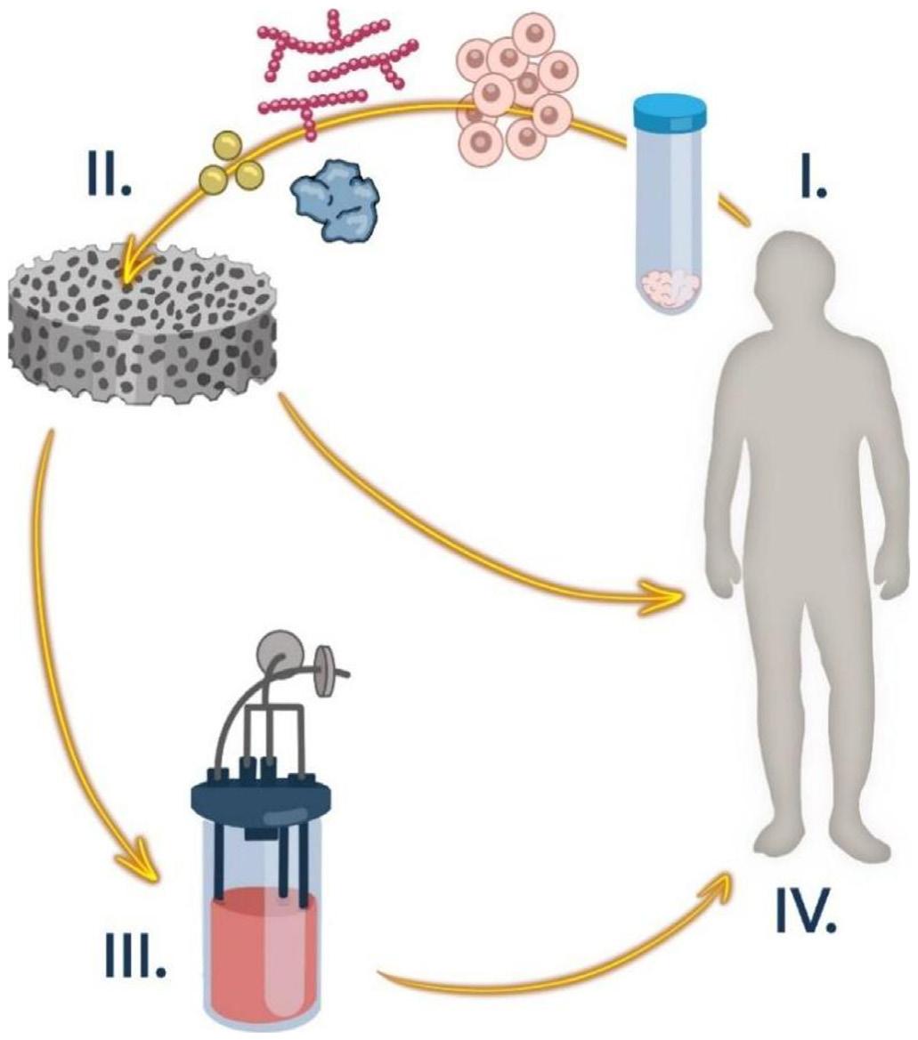
Figure 1 provides an overview of the steps involved in tissue engineering. The cells used can be autologous or allogeneic, differentiated (e.g., fibroblasts, chondrocytes, or keratinocytes) or stem cells, and originate from different sources[1]. Regardless of the source, cells can be cultured in vitro, either as isolated cells or in cultures, and then inoculated onto a matrix (scaffold) for subsequent administration to the patient or for in vivo implantation at the affected site. Cell adhesion to materials can be enhanced by incorporating signaling molecules, such as growth and differentiation factors. Additionally, bioreactors can be utilized to optimize these conditions. Once properly established, the cells begin to perform their physiological functions by secreting ECM compounds, thereby creating functional tissue. This system is then implanted at the site of injury so that it can eventually be replaced by the patient’s own regenerated tissue[1,8,15]
Tissue engineering is based on the concept that an artificially synthesized matrix can replace and mimic the ECM and also perform its primary functions, thereby ensuring the integrity and regeneration of the affected tissue[11]. Therefore, to develop biomaterials capable of performing this function, it is essential to understand ECM and its interactions with cells. The ECM is a natural scaffold, filling the intercellular space. It is composed of molecules secreted by local cells, mainly proteins and polysaccharides, which vary depending on the tissue type. The ECM is a significant element of connective tissues, where its components are mainly synthesized and secreted by fibroblasts[11,16,17]
Fibrous scaffolds for tissue engineering: from conceptualization to implementation
The ECM participates in diverse events such as morphogenesis and tissue homeostasis by regulating cell physiology, as well as in cell adhesion, growth, differentiation, migration, and apoptosis, all of which are mediated by cell signaling pathways[11]. Furthermore, as previously mentioned, the composition of the ECM varies according to the type of tissue, with distinct physical and chemical characteristics that result in different functions. For example, the ECM provides interconnection, support, and nutrition in loose connective tissues; mechanical support, lubrication, and elasticity in cartilage; hardness and mechanical strength in bone, and transparency and refraction in the cornea[16]
Cellular receptors are essential for the transmission of information between cells, tissues, and organs. Among their diverse functions, these receptors capture extracellular signals and convert them into a cascade of reactions that elicit a cellular response. The receptors (generally integrins) recognize ECM molecules and enable interactions between this matrix and cells. In addition to integrins, other proteins are involved in ECM recognition, such as the arginine-glycine-aspartic acid (RGD) amino acid sequence, fibrinogen, collagen, and fibronectin; these molecules can be incorporated into scaffolds designed to replace the ECM[11 16]
2.2 Biomaterials and biocompatibility: history and definitions
In 1987, the European Society for Biomaterials defined a biomaterial as a non-biological material used in medical devices with the specific purpose of interacting with a biological system. However, the concept of biomaterials has been updated over the years. Currently, biomaterials are defined as materials that actively interact with a biological system in order to evaluate, treat, or replace a tissue or the function of an organ[18-20]. The evolution of biomaterials is closely associated with the functions they have served over time. Between the 1960s and 1970s, the concept of biomaterials focused on developing inert devices primarily intended to provide mechanical support for hard tissues. The second generation (1980-1990) introduced a new perspective of biomaterials, utilizing chemical interactions between tissues and bioactive materials. Later, to solve rejection issues caused by bioactive materials, bioresorbable biomaterials were developed. These materials can be degraded and eliminated by the body’s natural physiological processes, excluding the need for surgical removal of implants. Finally, the current generation of biomaterials, also referred as “smart” materials (which respond to external stimuli such as temperature and pH) and “biomimetic” materials (inspired by natural structures and capable of simulating tissues like bone and cartilage), is designed to mimic natural organization and functionality, promoting repair and regeneration of damaged tissue[19]
Biocompatibility is one of the most relevant criteria of the acceptance of a biomaterial. The definition of biocompatibility has undergone several changes over time, and there is still no universal consensus on its precise meaning. The most widely accepted definition describes biocompatibility as the ability of a material to perform with an appropriate host response in a specific application. However, various authors have proposed updates to this interpretation, such as emphasizing that the material must interact with living systems without posing risks to the host’s health[21,22]
Chen and Thouas[23] define biocompatibility as a factor that can be assessed based on parameters such as cell viability, tissue response, tumor formation, genetic integrity, immune reaction, and blood clotting potential. According to Crawford et al.[20], biocompatibility is the ability of the material to locally activate and guide host proteins and cells towards tissue reconstruction without the formation of a fibrous capsule and to enable vascularization and integration of the damaged tissue.
Numerous factors must be considered when evaluating a material’s biocompatibility: the physical and chemical properties, the duration of exposure to the tissue, the release of residues, and the characteristics of the affected tissue itself[8] However, Williams[24] suggests that biocompatibility should not be viewed as an inherent property of the material alone but rather of the biomaterial-tissue system, since the same material can elicit different responses depending on the site of application. Generally, all definitions of biocompatibility involve beneficial interaction between the tissue and the material, varying according to the desired performance or function of the biomaterial[18]. Biocompatibility encompasses not only chemical compatibility with cells but also factors such as design (e.g., architecture, topology, electrical and mechanical properties). Also, research indicates that, although chemical composition is important, surface roughness plays a more significant role in influencing cellular responses[18,24-26].
The human body has a complex defense system against foreign substances from the external environment, whether living or not-living. Medications such as immunosuppressants are often used to prevent the rejection of implants or transplants. However, the resulting weakened immune system significantly increases the patient’s susceptibility to diseases and infections. To control these undesirable reactions, tissue engineering seeks to develop scaffolds with physical, chemical, and biological properties like those of the specific tissue. These scaffolds not only help prevent rejection but also promote cell adhesion, differentiation, and proliferation, ensuring the maintenance of the original function of the affected tissue[6,24]
The primary requirement for cells to survive on a scaffold is cell adhesion. This initial stage of interaction between the material and the cell critically influences cell viability, growth, and differentiation. Cells generally adhere to surfaces through specific proteins (e.g., integrins) and those unable to adhere generally undergo cell death. Additionally, cell adhesion plays an important role in cellular communication, regulation, as well as in organ formation, and tissue maintenance[17,27]. Therefore, studying mechanisms of cell adhesion to the scaffold surface requires an understanding of cell adhesion to the ECM during tissue formation[8,28] The adhesion of cells to a scaffold is directly related to the physicochemical properties and topology of the material.
As previously mentioned, each tissue possesses unique characteristics. Scaffold morphology, for example, can influence cell behavior; at the microscale, it affects cell morphology, while at the nanoscale, regulates subcellular
Iguma, T. S., Nascimento, V. A., Giorno, L. P., Malmonge, S. M., & Santos Jr., A. R.
recognition mechanisms. Furthermore, the material’s surface plays an important role by influencing the initial sequence of adsorbed proteins, as well as interaction with blood, inflammatory responses, and other vital cellular activities[27] Among the topological properties, surface roughness and porosity should be highlighted[17,18]
Roughness is a key factor in the success of cell adhesion, with studies indicating that it is even more influential than the cell type or the biomaterial of the scaffold. Surface roughness can be categorized into different scales: macroscopic, microscopic, submicron, and nanometer roughness. Macroscopic roughness (>100 μm) does not significantly affect cell adhesion, as there is sufficient space for cells to spread in the free spaces; however, it can affect the arrangement of cells within a colony (a set of cells that form the tissue). The micro and submicron scales (0.1-100 μm) can affect individual cells and play a more significant role in cell adhesion and growth. Nevertheless, these characteristics are even more susceptible to nanoroughness (1-100 nm) because this scale closely matches that of cell receptors, directly impacting protein adsorption, cell proliferation, and differentiation[17,27]
The architecture of the device also plays a relevant role in biocompatibility. Scaffold morphology can range from spongy to fibrous, as long as it contains interconnected pores that create an adequate environment for cell infiltration, proliferation, and differentiation. These pores should also enable the flow of nutrients, gases, and cellular waste. For temporary and bioresorbable implants, the pores must allow cells to produce ECM replacement as it degrades. Additionally, the pore size and distribution affect macrophage infiltration, neovascularization, ECM remodeling, and the overall healing process[27,29,30] .
In principle, a more porous matrix with larger pores may be advantageous for cell migration, distribution, nutrient flow, and neovascularization. However, smaller pores provide a greater specific surface area formed by the internal walls of the scaffold, which also promotes cell adhesion[6,27,29] Therefore, a balance between these properties is necessary, as each tissue or cell type requires specific pore sizes. It is important to note that all the aforementioned prerequisites depend directly on the material used and the fabrication process, which will be discussed below.
2.5 Effect of physical properties of the scaffold on cell adhesion
To produce an effective scaffold, it is essential to consider its mechanical properties, as the structure must
provide characteristics like those of the original tissue, even if only temporarily. The ECM of most soft tissues exhibits nonlinear elasticity, i.e., it stiffens in response to increased tension. This mechanism helps prevent the loss of tissue structural integrity and permanent deformations[31,32] Nevertheless, developing a scaffold with mechanical properties corresponding to those of the affected tissue is challenging because different tissue types have specific properties, in addition to being subjected to different mechanical stresses. For example, cardiac tissue requires a material with high resilience, resistance, and durability, as well as electrical conductivity to facilitate the propagation of electrical impulses. In contrast, bone tissue demands a material with high rigidity and resistance, particularly to withstand compression, traction, and flexural forces[29,33] .
The stiffness of the ECM can vary widely, ranging from approximately 0.1 kPa (brain) to 100 GPa (bone) and is primarily determined by its composition of collagen and elastin. Matrix stiffness is not only structurally important but also directly influences cellular activities such as adhesion, differentiation, cytoskeletal remodeling, and intercellular interactions. Generally, the looser the bonds and the lower the ECM stiffness, the less mechanical feedback is required to recruit integrin complexes for cell signaling and adhesion; conversely, this process tends to increase with greater matrix stiffness[17,34]. Additionally, scaffolds must possess sufficient pores and interconnectivity to facilitate cell migration, adhesion, proliferation, and flow of nutrients and waste. Therefore, an optimal pore number, distribution, and size are essential without compromising the scaffold’s mechanical integrity. Finally, the mechanical properties of the scaffold should generally last until tissue regeneration period, which varies depending on the tissue type, as well as the patient’s age and other conditions[6,29]
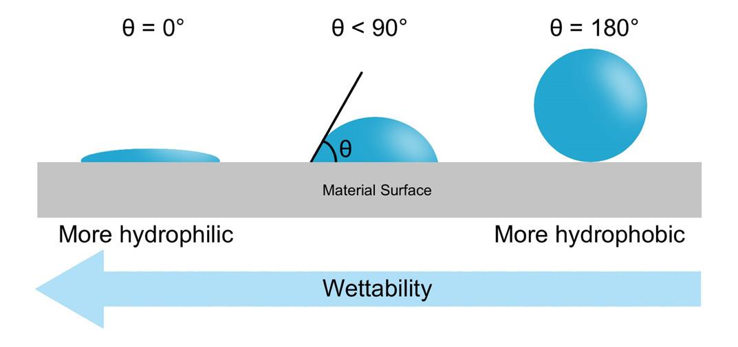
The first parameter to consider when analyzing cell adhesion to a scaffold is the wettability of the material, which determines its hydrophilicity (Figure 2). Although hydrophilic materials generally promote cell adhesion, proteins tend to adsorb more readily onto hydrophobic surfaces; therefore, a balance between these properties is essential. Like superhydrophobic materials (θ > 150°), superhydrophilic materials (θ < 5°) are also unable to support cell adhesion and growth[11,17]. Physical adsorption is mediated by weak intermolecular forces, such as Van der Waals and electrostatic interactions, and occurs more rapidly when there is charge difference between cell membrane molecules and the material surface[8,11].
Fibrous scaffolds for tissue engineering: from conceptualization to implementation
The water layer formed on the surface of the biomaterial mediates its hydroxylation (the formation of −OH groups) through the dissociation of water molecules upon contact with a hydrophilic surface. This process enables the biomaterial to interact with proteins present in body fluids. First, small proteins (e.g., albumin) reach and adsorb onto the biomaterial. Subsequently, larger proteins with a higher affinity for the molecular groups on the scaffold surface force desorption of smaller proteins (Vroman effect) and can influence cell adhesion. This competition among proteins for surface sites is dynamic and complex, depending on various factors such as protein concentration in the fluid[11]. Additional important factors influence protein adsorption, including temperature, pH, ionic strength, and electrostatic interactions[27]
The chemical properties of a biomaterial play a fundamental role in cell adhesion. One of the most important properties is surface energy (also called interfacial free energy or surface free energy), which relates to the number of ruptured intermolecular bonds present on the surface of a solid. The higher the surface free energy, the more easily cells adhere and spread; in other words, the greater the wettability of the biomaterial. However, it should be noted that certain proteins preferentially adsorb onto surfaces with lower free energy[17] . In addition to surface energy, we highlight the importance of the surface charge (determined mainly by functional chemical groups), as it can also affect cell adhesion. Generally, cells adhere more readily to positively charged surfaces[35]. However, research suggests that negative charges can enhance protein adsorption, thereby promoting cell adhesion. It is important to note that, as with other properties, the type of cell influences adhesion success in relation to chemical properties, and no universal model applies to all cell types[17] .
Biomaterials can be classified into three groups: bioinert, bioactive, and bioresorbable. The primary characteristic of bioinert materials is the minimal interaction at the interface between the material and biological tissue. Generally, the tissues exhibit a minimal response, which often form a fibrous capsule around the interface. Bioactive materials can significantly interact with tissue through chemical bonding. Finally, bioresorbable materials do not require surgical removal because since they degrade over time, their residues are naturally absorbed and eliminated by the body. Generally, bioinert materials are metals or ceramics, while bioresorbable materials are commonly polymers[13,36,37]
The most widely used classes of biomaterials in tissue engineering are ceramics and polymers. Ceramics are commonly employed in applications involving hard tissues due to their equivalent mechanical properties. Hydroxyapatite and tricalcium phosphate are examples of ceramics used for bone tissue repair; they exhibit bioactivity that stimulates the differentiation and proliferation of osteoblasts[6,38] . Polymeric materials, on the other hand, are more versatile and have broader applications.
Polymeric materials can be classified into two categories: synthetic and natural. Synthetic polymers are laboratory-synthesized materials typically derived from non-renewable sources.
Their primary advantages include ease fabrication and greater versatility, as they can be custom-made and produced on a large scale. Additionally, their production costs are generally lower. These materials exhibit more standardized characteristics, and their manufacturing processes can be more easily manipulated to improve their properties. However, synthetic polymers may exhibit cytotoxicity-related problems, increasing the risk of rejection[39,40]
Natural polymers, in contrast, often exhibit greater similarity to the ECM because they are derived from biological sources, such as proteins or polysaccharides. Consequently, their biocompatibility is generally higher than that of synthetic polymers. However, natural polymers can be more difficult to manipulate and less homogeneous, i.e., their properties and composition vary depending on the source material. Natural polymers typically have inferior mechanical properties compared to synthetic polymers[39,41,42] .
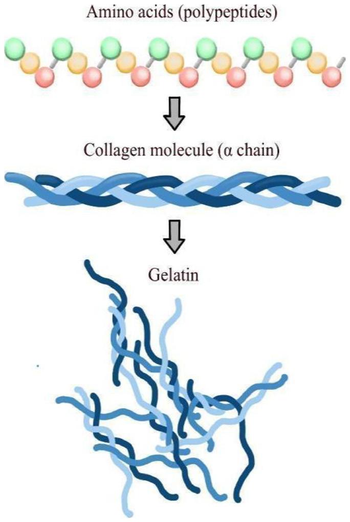
Despite their disadvantages, natural polymers such as collagen and gelatin present promising solutions for tissue engineering. Collagen is a high-molecular-weight protein and the most abundant biopolymer in mammals, particularly types I and II. This protein is found in the ECM of both hard and soft connective tissues, where it provides structural stability[6,39,41] . Collagen is converted into gelatin through partial hydrolysis, which results in the loss of its tertiary and quaternary structures. Since gelatin is derived from collagen, it shares many similar properties[29 43 44]. For these reasons, collagen and gelatin hold significant potential as biomaterials and could be widely utilized in biomedical and pharmaceutical applications. These biopolymers can be obtained from a variety of animal tissues, including those of cattle, pigs, and birds. However, from a commercial perspective, collagen is primarily obtained from the skin and tendons of cattle and pigs[45 46]
Collagen is produced by various cell types, including chondroblasts, osteoblasts, epithelial cells and, mainly, fibroblasts. It is an abundant protein present in the ECM that directly promotes cell anchorage and new tissue formation or indirectly influences these processes through collagen receptors such as fibronectin and laminin found on cells[47] Like all proteins, collagen is composed of amino acids linked by covalent (peptide) bonds, which organize into a helical α-helix structure consisting of three molecular chains (tropocollagen) stabilized by secondary (weaker) bonds. These α-chains aggregate to form collagen fibers[39,48]
The primary structure of collagen consists of approximately 1,000 amino acids that form either identical or non-identical polypeptide chains. The most common repeating sequence in the collagen molecule is glycine-X-Y, where X and Y are predominantly proline and hydroxyproline[43,49]. Glycine is a small amino acid, typically located in the inner part of the helix. The composition and distribution of glycine are therefore responsible for the protein’s native state. Proline and hydroxyproline have rigid side rings, which result in steric hindrances that help maintain structural stability. Intramolecular hydrogen bonds also contribute to the stability of the secondary structure, while crosslinks are essential for preserving the fibrous structure[39,48,50]
Iguma, T. S., Nascimento, V. A., Giorno, L. P., Malmonge, S. M., & Santos Jr., A. R.
The helical conformation of collagen fibers, determined by the physicochemical properties of their constituent amino acids, ensures the tissue’s strength. Collagen molecules within the fibers are stabilized by various inter- and intramolecular forces, such as hydrogen bonds between NH and C=O groups oriented perpendicular to the fiber axis. These bonds promote strong interactions between neighboring molecules; thus, when a force is applied, it is distributed across the fiber to adjacent collagen molecules. Furthermore, the fibers present in tissues can naturally form crosslinks, ensuring high stability and tensile strength. There is a wide variety of collagen types, including type I (the most common), abundant in skin, tendons, and bones; type II, found in cartilage; and type III, present in skin and blood vessels[39,48,50]
Although collagen is a stable molecule that is generally insoluble in water, like other proteins, it can undergo denaturation and may revert to its primary structure under certain conditions. Temperature-induced denaturation also depends on factors such as water content, pH of the medium, and the density of crosslinks. However, once the denaturation temperature is reached, only the weak intramolecular bonds are broken, while the covalent intermolecular bonds remain intact. Consequently, the three chains that form the α-helix separate and disperse into the aqueous medium, resulting in a colloidal system. When the temperature is lowered again, the collagen chains rearrange, and hydrogen bonds form between water molecules and the collagen, leading to the formation of gelatin[45,48,50]
Gelatin is a biopolymer produced by the partial hydrolysis of collagen, primarily involving the loss of its tertiary and quaternary structure, generating a colloidal system (Figure 3). Gelatin is derived from type I collagen-rich tissues of animals such as cattle, pigs, birds, and fish. Its extraction properties vary not only according to the animal species but also with age, tissue of origin, and collagen type. Furthermore, the amino acid distribution differs depending on the animal source; for example, gelatins derived from pigs and cattle lack cysteine residues, while those obtained from fish contain less glycine compared to mammalian gelatins. Gelatin is produced by pretreating collagen in acidic, alkaline, or enzymatic medium; the first two being the most common. When an acidic medium is used, type A gelatin is formed, which has an isoelectric point between 8 and 9, whereas gelatin B with an isoelectric point between 4 and 5, is produced in an alkaline medium. The pretreatment of collagen breaks non-covalent bonds such as hydrogen bonds, hydrophobic interactions, and crosslinks, leading to the disruption of the triple-helix structure. This loosens the chains, facilitating their swelling and the solubilization of collagen, which is necessary for the gelatin extraction. The pretreated collagen is then immersed in a saline or acid solution, followed by filtration of the biopolymer, evaporation, drying, grinding, and sieving until the gelatin becomes powder[29,43,44,48,51]
Regarding its biological properties, gelatin, being derived from collagen, retains several notable characteristics relevant to cell-biomaterial interactions, such as biocompatibility, bioresorption, and the ability to mimic the ECM. Consequently, it is a promising material for scaffold fabrication[44,51,52]
Gelatin contains integrin-binding sites that facilitate cell adhesion. Additionally, gelatin exhibits lower antigenicity and immunogenicity compared to collagen. Its production costs are also lower, making gelatin a preferred choice over collagen scaffold manufacturing. Other advantageous properties include its natural abundance, biodegradability, and the aforementioned biocompatibility[53-59]
Unlike collagen, gelatin dissolves spontaneously in aqueous solutions and can undergo a sol-gel transition depending on its type, concentration, and temperature. This process is reversible and involves the transition between a random colloidal system and the partial restoration of collagen triple helices. However, this sol-gel transition can pose challenges for certain biological applications because gelatin in the gel phase loses its structure at body temperature, reverting to the fluid state (sol phase). To maintain gelatin in the gel phase, crosslinking (the formation of crosslinks) is necessary. Crosslinks enhance the material’s mechanical properties, making it insoluble in water and stable under biological conditions. Crosslinking can be achieved through three main methods: chemical, physical, and enzymatic[44,51,52]
Physical crosslinking is a technique that employs irradiation, plasma, or dehydrothermal treatment. A specific physical stimulus induces the separation of polymer chains, generating free radicals that bind to each other, resulting in crosslinks. The primary advantage of this method is its lower cytotoxicity, as it does not produce potentially toxic compounds within the chains and eliminates the need for solvents. Additionally, irradiation can simultaneously sterilize the material while promoting crosslinking. However, these physical methods are less efficient at forming crosslinks and yield polymers with inferior mechanical properties compared to those produced by chemical methods. Enzymatic crosslinking utilizes transglutaminase; an enzyme found in certain plants and animals. This enzyme facilitates crosslinking through an acyltransferase reaction between the glutamine residue of one chain and the amine group of another[44,51,52].
Fibrous scaffolds for tissue engineering: from conceptualization to implementation
Chemical crosslinking, currently the most widely used method, offers a broader range of options compared to other techniques. This process involves forming covalent bonds between polymer chains, resulting in more stable structures with better-controlled physicochemical properties than those achieved by physical crosslinking. Chemical crosslinking agents are classified into two categories: zero-length and non-zero-length crosslinkers. Zero-length crosslinking creates direct bonds between peptide chains, with the reagent being completely removed after the reaction; thus, the crosslinker acts as a catalyst and is not incorporated into the final gelatin structure. The advantage of this approach is the preservation of the gelatin structure, ensuring good biocompatibility and high conversion efficiency. In contrast, non-zero-length method forms crosslinks by incorporating the crosslinker molecules into the final gelatin structure[51]. This technique generally provides good crosslinking efficiency, which correlates with enhanced hydrogel stability, but it may also cause cytotoxicity-related issues. Notable examples of method include the use of glutaraldehyde (GA), as well as the combination of N-ethyl-N’-(3-dimethylaminopropyl) carbodiimide with N-hydroxysuccinimide (EDC/NHS)[44,52]
Although GA is an effective crosslinking agent for fibrous scaffolds derived from natural proteins, its use presents significant challenges due to its inherent cytotoxicity. If GA residues are not completely neutralized or removed, they can compromise cell viability in vitro and induce harmful inflammatory responses in vivo. Consequently, tissue engineering research has increasingly focused on less toxic alternatives, which can be broadly categorized as chemical or physical methods. Chemical alternatives include the EDC/NHS system (a zero-length crosslinker that does not incorporate into the final bond), PEGDE (Poly(ethylene glycol) diglycidyl ether, known for its high biocompatibility), and genipin (a naturally derived crosslinker). Physical methods include Dehydrothermal Treatment (DHT) and controlled application of UV/Gamma radiation, thereby ensuring the necessary safety and biocompatibility for the clinical application of these scaffolds[51,52]
Poly(ɛ-caprolactone) (PCL) is an aliphatic, bioresorbable, linear synthetic polyester distinguished by its ability to be molded into various shapes, setting it apart from other biomaterials used in scaffold development. It exhibits excellent thermal stability, and it is susceptible to surface modifications. Its physicochemical, mechanical, and biocompatibility properties can be significantly altered, while its hydrophobicity and degradation behavior are influenced by surface and structural modifications of the scaffolds[60]. PCL has a glass transition temperature of -60 °C, a melting point ranging from 59 to 64 °C, and a hydrophobic, and semicrystalline nature that tends to decrease with increasing molecular weight[61]. This polymer can be synthesized via ring-opening polymerization of the lactone or by condensation of 6-hydroxyhexanoic acid through catalyzed reactions under appropriate conditions[62]
PCL is easy to process and characterize, also being soluble in various organic solvents. Additionally, it exhibits
properties such as high toughness, biocompatibility, and bioresorbability. The versatility and safety of this polymer enable its use in controlled drug release applications, blend scaffold fabrication, bone regeneration, and vascular grafting. Consequently, PCL has been approved by the United States Food and Drug Administration (FDA) for clinical and therapeutic use[61]. When in contact with body fluids, PCL degrades on its surface through non-enzymatic hydrolytic cleavage of the ester groups in its structure. This reaction produces lower molecular weight fragments by diffusion of oligomers from the polymer matrix (which does not imply a loss of molecular mass), generating soluble and non-toxic oligomers. Upon exposure to the body’s metabolism, the carboxylic acids released during hydrolysis are further degraded and converted into CO2 and H2O, which are eliminated through the body’s natural mechanisms. As a result of these reactions, the polymer’s molecular weight and crystallinity decrease[62,63]
The kinetics of the polymer-organism interaction during bioresorption promote cell proliferation and the secretion of the ECM, which occupies the space previously filled by the polymer. Thus, tissue repair occurs gradually as the material degrades, which is the desired outcome in clinical practice. However, the ability of PCL to stimulate cell adhesion and proliferation is limited, making its combination with other polymers particularly relevant[61]
Given the need for a biocompatible environment that supports the establishment of cells and tissues, polymers are particularly attractive for scaffold design due to their versatility and broad applicability in soft tissues, along with a variety of fabrication techniques. These techniques enable the development of structures that closely mimic the original tissue; for example, fibrous polymeric structures exhibit a high morphological similarity to the ECM[10,64,65]. In this context, both the choice of polymer and the fabrication method can be optimized by considering the relationship between the specific physicochemical properties of each material and the characteristics of the processing techniques used.
Since PCL is a polymer with a semicrystalline structure, high viscosity, and heat resistance, it can be easily manipulated and spun into continuous, uniform fibers using rotary jet spinning. This technique is particularly effective for producing micrometer-scale fibers with superior mechanical properties, making them suitable for applications requiring strong structures such as bone regeneration. On the other hand, gelatin is a natural protein with low thermal stability that tends to form low-viscosity solutions, characteristics that make it more suitable for electrospinning. This process employs a strong electric field to stretch a polymer solution into ultrafine fibers. Due to its ability to create nanoscale fiber networks, electrospinning is ideal for materials such as gelatin, which benefit from highly porous structures with a large surface area. These structures are especially advantageous in tissue engineering applications, where promoting cell adhesion and proliferation, along with nutrient diffusion, is critical[66]
Iguma, T. S., Nascimento, V. A., Giorno, L. P., Malmonge, S. M., & Santos Jr., A. R.
As previously mentioned, since gelatin is derived from collagen, it possesses biologically advantageous properties as a biomaterial. Gelatin is used in bulk form, as fibers, and as a carrier for drugs and cells, in addition to several other applications across various tissues such as bone, skeletal muscle, and neural tissues[67-69]. Furthermore, different scaffold fabrication techniques have been well described in the literature, including electrospinning, rotary jet spinning, and solution blow spinning.
Electrospinning is one of the most widely used techniques, employing a high-voltage power supply to generate an electric field that facilitates the extrusion of material through a Taylor cone[70,71]. The process involves charging the polymer using a potential difference and consists of three main components: a high-voltage power supply, a syringe with a capillary, and a grounded collector (typically a metal plate or a rotating mandrel). This setup allows the material to be accelerated toward the oppositely charged collector, with the final fiber thickness controlled by the deposition time. Electrospinning enables the production of fibers with various interconnected porous structures, facilitating drug incorporation, enhanced mechanical properties, and improved chemical stability[71] Although the technique is highly versatile and widely used, it depends on the solution’s conductivity and the application of a high-voltage electric field, and its use is limited by low yield[10,71,72]. Electrospinning has been used to fabricate PCL-gelatin nanofibers combined with bone marrow-derived mesenchymal stem cells (BMSCs). Studies show that this scaffold, when applied to skin wounds, enhances cell adhesion and proliferation in vitro. In vivo, the material promotes improved wound contraction and accelerates re-epithelialization[73]. Furthermore, when applied to bone regeneration, the PCL-gelatin mesh serves as a robust three-dimensional niche capable of modulating and optimizing the therapeutic performance of BMSCs, thereby promoting osteogenesis[74] .
Rotary jet spinning enables the production of anisotropic fiber matrices by extruding material through centrifugal forces via capillaries on the lateral surface of a rotating reservoir. This technique is efficient, lowcost, and insensitive to the dielectric constant of the materials. It does not require high-voltage electric fields and demonstrates high reproducibility[70,71]. The rotary jet spinning system consists of a reservoir that retains the solution flow, projecting it against the collector wall along a curvilinear trajectory (due to rotational inertia). The final characteristics of the fibers are closely linked to the fabrication process. Factors such as the choice of solvent, solution concentration, surface tension, orifice diameter and geometry, and rotation speed (which varies depending on the material) can control the porosity and diameter of the polymeric fiber. Additionally, the location where the fibers are collected within the device is an important factor[10,70,71,75,76]
Solution blow spinning is an alternative technique that combines electrospinning and melt blowing. It involves the controlled spraying of a polymer jet, which
is accelerated by a flow of compressed gas. The resulting fibers are then deposited onto a collector. This method has been adapted for applications such as drug delivery; however, the reproducibility of the formed fibers still requires further evaluation[10,77]. The airbrush is commonly used in solution blow spinning; it features a concentric nozzle that extrudes the polymer jet with the assistance of compressed gas. The injection rate can be regulated using an injection pump, while the pressure is controlled via an air compressor pressure regulator[78,79]. Although blow spinning is a good alternative to techniques such as electrospinning, it requires more sophisticated equipment, such as an injection pump. This technique employs a pistol fed with a polymer solution, which is extruded through a concentric nozzle using a stream of compressed gas (Figure 4). When the pistol is triggered, the system opens to supply both the polymer solution and compressed gas, forming a jet of polymer solution. The high-velocity gas flow generates shear forces at the gas/solution interface, deforming the polymer solution from a droplet into a conical shape[80,81]. The solvent in the solution evaporates along the jet path from the nozzle to the collector, resulting in fiber formation depending on the material and its viscosity. This technique can produce micro-, and nanofiber meshes with diverse characteristics, including variations in fiber diameter, morphology, alignment, and porosity[10,82]. It is also worth noting that the process uses compressed air at room temperature, preventing thermal degradation of the polymer[81]. Several parameters must be considered when airbrushing is employed: (a) solution properties: viscosity, concentration, surface tension, solvent nature; (b) processing conditions: pressure of the compressed gas and distance from the pistol nozzle to the collector (screen); (d) system characteristics: nozzle diameter and type of collector; and (d) environment factors: temperature, pressure, and humidity.
A comparison of the mentioned fiber formation methods, covering fiber diameter ranges, yield (g/relative smallest), solvents, polymer examples, advantages, limitations, and target applications, can be seen in Table 1
Among the parameters listed above, the concentration of the solution is one of the key features for fiber production, as it directly influences the material’s viscosity. The distance from the nozzle to the collector screen is also crucial for fiber formation. Generally, polymers with low intermolecular chain interactions lack sufficient fiberforming capacity; they tend to appear more diluted, often forming droplets that deposit as a film on the collector and may promote bead formation on the fibers. However, this can also arise if the solvent fails to evaporate upon extrusion, causing the material to reach the collector screen in a fluid state. Successful fiber production requires higher material concentration (and consequently greater viscosity) to ensure polymer chain cohesion without interruption[82]. Conversely, excessively viscous materials can hinder processing by clogging the nozzle. Therefore, it is essential to determine the optimal concentration and viscosity of the material when using airbrushing.
Fibrous scaffolds for tissue engineering: from conceptualization to implementation
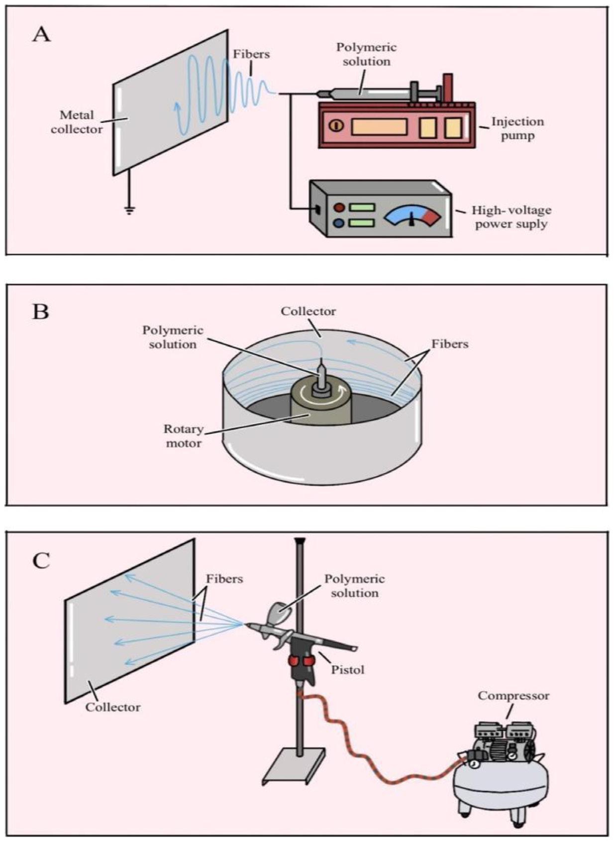
Figure 4. Schematic illustration of spinning techniques. (A) electrospinning; (B) rotary jet spinning; (C) airbrushing.
Table 1. Comparison of fiber spinning methods for tissue engineering.
Feature
Electrospinning (ES) Rotary Jet Spinning (RJS) Solution Blow Spinning (SBS)
Driving Force High-voltage electrostatic force. High-speed centrifugal/mechanical force. High-velocity compressed gas flow.
Fiber Diameter Range 20 nm up to 10 μm (Highest uniformity)
Production Yield (Lab Scale) Low to Moderate (E.g., 0.1−1 mL/h per needle; up to 0.1 g/h in single jets).
Solvents Used Wide range. Preference for polar solvents (E.g., DMF, THF, Chloroform, HFIP) due to conductivity.
Common Polymer Examples Natural: Collagen, Gelatin, Silk, Chitosan, Hyaluronic Acid. Synthetic: PCL, PLA, PGA, PLLA, PU.
Advantages - Diameter Control: Produces the finest and most uniform fibers (nanofibers). - Alignment: Easily produces aligned fibers (using rotating collectors). - Versatility: Wide range of polymers and controllable fiber morphologies.
Limitations - Low Yield: Slow at the laboratory scale. - Scalability: Challenging due to jet instabilities and need for multi-jet systems. - Environment: Sensitive to humidity/temperature. Requires high voltage (safety risk).
Target Applications
High-precision scaffolds, specialized filtration membranes, controlled drug delivery systems.
50 nm up to several μm. 100 nm up to several μm.
High (E.g., up to 60 g/h per orifice; up to 12,000 g/h at industrial scale).
Wide range. Higher tolerance for volatile solvents and can also use polymer melts (melt spinning).
PCL, PLA, PU, Polyamides (PA6). Broad range, including highviscosity or melt polymers.
- High Throughput: Excellent scalability for mass production.Cost/Safety: Does not require high voltage, simpler, safer process. - Viscosity: Can process more concentrated solutions and melts.
- Uniformity: Broader distribution in fiber diameter and morphology (higher D.P.). - Control: Less precise control over 2D deposition/ alignment structure.
Large-scale wound dressings, technical textiles, large scaffolds for soft tissues (muscle, skin).
High (Typically 10x or more faster than ES; high polymer injection rate).
Preference for highly volatile solvents (E.g., Acetone, Chloroform/ Acetone) for rapid evaporation.
PCL, PLLA, PVA, PE/PP. Suitable for a wide range, but favors lower viscosity solutions.
- High Throughput: Very fast and continuous production. - Portability: Simple, low-cost equipment, potential for in situ production.Solution Requirements: Does not require solution conductivity.
- Uniformity: Larger diameter and variation compared to ES. - Defects: May have more defects or “beads” due to high injection/evaporation rate.
Low-cost wound dressings, coatings, and membranes for bioengineering where nanometric uniformity is not critical.
Iguma, T. S., Nascimento, V. A., Giorno, L. P., Malmonge, S. M., & Santos Jr., A. R.
The successful translation of tissue-engineered constructs into clinical practice represents a significant challenge in regenerative medicine. As emphasized in analyses of personalized scaffolds and perspectives on clinical translation, and consistent with the identified barriers to translation and commercialization, transitioning from a laboratory concept to a commercial product requires overcoming critical, interconnected regulatory and technical obstacles.
The regulatory complexity and challenges of clinical translation present significant issues, with the regulatory system serving as the primary and most crucial barrier. In the United States, the Food and Drug Administration (FDA) classifies tissue-engineered medical products (TEMPs) as devices, biologics, drugs, or combination products. This classification determines the approval pathway, requiring comprehensive preclinical testing to demonstrate both safety and efficacy, along with stringent ethical considerations regarding cell sources, donor consent, and the conduct of clinical trials[83,84]
Scalability, reproducibility, and adherence to manufacturing standards are essential. Transitioning to large-scale production requires implementing a rigorous quality management system, primarily governed by Good Manufacturing Practices (GMP), which is a complex challenge for products developed from laboratory-scale processes. Similarly, maintaining manufacturing reproducibility is crucial, as consistent replication and assurance of batch quality are vital. In the context of personalized bioengineered implants, which utilize techniques such as 3D biofabrication, the challenge lies in balancing anatomical and functional customization (essential for clinical success in applications like craniofacial reconstruction) with process standardization. Any variability in scaffold composition, mechanical properties, or fibrous architecture can affect host integration and long-term performance[83 85]
Furthermore, scalability in industrial production requires the development of standardized workflows for all stages, from the rational selection of biomaterials to final fabrication. This approach eliminates the artisanal nature of bench research, enabling the volume and costeffectiveness necessary for commercial viability. Additionally, critical technical challenges must be addressed, including sterilization and biocompatibility (two essential factors for clinical acceptance of the product). Many biomaterials, particularly polymers sensitive to temperature or radiation and constructs incorporating growth factors or cells are vulnerable to conventional sterilization methods. The challenge lies in developing and validating sterilization protocols that effectively eliminate microorganisms without compromising the material’s structural integrity, mechanical properties, or bioactivity. Moreover, demonstrating biological safety is mandatory and must comply with international standards, such as the ISO 10993 series. Testing must confirm the absence of cytotoxicity and genotoxicity, ensure an appropriate inflammatory response, and verify predictable scaffold degradation within the physiological environment[83,86]
In summary, clinical translation requires bridging biological innovation with engineering precision. Success depends on the ability to integrate an optimal scaffold design with reproducible, sterilizable, and scalable manufacturing processes, all within a stringent regulatory framework that ensures long-term safety and efficacy.
A series of technical and scientific challenges must be addressed to ensure the viability of scaffold production and its application in tissue engineering. Controlling and standardizing operational parameters are essential for producing fibrous scaffolds from polymeric materials with properties suitable for biotechnological applications. The optimal scaffold design also depends on the characteristics of the target tissue, including whether the fibers are thin or thick, and whether their orientation is aligned (as in tendons) or random (as in skin). The polymer’s bioactivity and resorption time are critical factors, as is the consideration of tissue characteristics during repair. Additionally, given the high demand, the scalability of scaffold method used for the production methods must be carefully evaluated. There are many challenges to overcome; however, by mimicking the tissue environment, fibrous materials play a key role in biotechnological procedures used in tissue engineering.
● Conceptualization – Arnaldo Rodrigues Santos Jr.
● Data curation – Thais Sayuri Iguma; Vitor Andrade Nascimento; Luciana Pastena Giorno; Sônia Maria Malmonge; Arnaldo Rodrigues Santos Jr.
● Formal analysis – Thais Sayuri Iguma; Vitor Andrade Nascimento; Luciana Pastena Giorno
● Funding acquisition – Arnaldo Rodrigues Santos Jr.
● Investigation – Thais Sayuri Iguma; Vitor Andrade Nascimento; Luciana Pastena Giorno
● Methodology – Thais Sayuri Iguma; Vitor Andrade Nascimento; Luciana Pastena Giorno
● Project administration – Sônia Maria Malmonge; Arnaldo Rodrigues Santos Jr.
● Resources – Sônia Maria Malmonge; Arnaldo Rodrigues Santos Jr.
● Software – NA.
● Supervision – Sônia Maria Malmonge; Arnaldo Rodrigues Santos Jr.
● Validation – Sônia Maria Malmonge; Arnaldo Rodrigues Santos Jr.
● Visualization – Thais Sayuri Iguma
● Writing – Thais Sayuri Iguma; Vitor Andrade Nascimento; Luciana Pastena Giorno
● Writing – review & editing – Thais Sayuri Iguma; Vitor Andrade Nascimento; Luciana Pastena Giorno; Sônia Maria Malmonge; Arnaldo Rodrigues Santos Jr.
Fibrous
for tissue engineering: from conceptualization to implementation
The authors wish to thank the National Council for Scientific and Technological Development (CNPq), process number 404701/2023-0, for financial support.
1 Brasil Ministério da Saúde. (2025). Relatórios de lista de espera. Retrieved in 2025, August 13, from https://www.gov. br/saude/pt-br/composicao/saes/snt/relatorios/lista-de-esperaserie-historica
2 Santos, A. R., Jr. (2010). Bioresorbable polymers for tissue engineering. In D. Erbeli (Ed.), Tissue engineering (pp. 225-246). London: IntechOpen https://doi.org/10.5772/8580
3 Silva, A., Arora, S., Dhanani, S., Hornby, L., Luctkar-Flude, M., Ross-White, A., Lotherington, K., Rochon, A., Wilson, L., Latifi, M., Giorno, L., & Silva e Silva, V. (2022). Quality improvement tools to manage deceased organ donation processes: a scoping review protocol. Nurse Education in Practice, 61, 103322 https://doi.org/10.1016/j.nepr.2022.103322 PMid:35306317.
4 Sanjanwala, D., Londhe, V., Trivedi, R., Bonde, S., Sawarkar, S., Kale, V., & Patravale, V. (2024). Polysaccharide-based hydrogels for medical devices, implants and tissue engineering: a review. International Journal of Biological Macromolecules, 256(Pt 2), 128488 https://doi.org/10.1016/j.ijbiomac.2023.128488 PMid:38043653.
5 Cao, L., Su, H., Si, M., Xu, J., Chang, X., Lv, J., & Zhai, Y. (2021). Tissue engineering in stomatology: a review of potential approaches for oral disease treatments. Frontiers in Bioengineering and Biotechnology, 9, 662418 https://doi. org/10.3389/fbioe.2021.662418. PMid:34820359.
6 Marsudi, M. A., Ariski, R. T., Wibowo, A., Cooper, G., Barlian, A., Rachmantyo, R., & Bartolo, P. J. D. S. (2021). Conductive polymeric-based electroactive scaffolds for tissue engineering applications: current progress and challenges from biomaterials and manufacturing perspectives. International Journal of Molecular Sciences, 22(21), 11543 https://doi.org/10.3390/ ijms222111543 PMid:34768972.
7 Baudequin, T., & Tabrizian, M. (2018). Multilineage constructs for scaffold‐based tissue engineering: a review of tissue‐specific challenges. Advanced Healthcare Materials, 7(3), 1700734 https://doi.org/10.1002/adhm.201700734. PMid:29193897.
8 Oréfice, R. L., Pereira, M. M., & Mansur, H. S. (2012). Biomateriais: fundamentos e aplicações Rio de Janeiro: Guanabara Koogan
9 Sun, W., Gregory, D. A., Tomeh, M. A., & Zhao, X. (2021). Silk fibroin as a functional biomaterial for tissue engineering. International Journal of Molecular Sciences, 22(3), 1499 https://doi.org/10.3390/ijms22031499. PMid:33540895.
10 Iguma, T. S., Malmonge, S. M., & Santos, A. R., Jr. (2019). Natural fibrous polymers for tissue engineering. Stem Cell and Regenerative Medicine, 3(1), 1-4 https://doi.org/10.33425/26399512.1037
11 Bandzerewicz, A., & Gadomska-Gajadhur, A. (2022). Into the tissues: Extracellular matrix and its artificial substitutes: cell signalling mechanisms. Cells, 11(5), 914. https://doi. org/10.3390/cells11050914 PMid:35269536.
12 Kaasi, A., & Jardini, A. L. (2016). Bioreactors. In S. Hashmi (Ed.), Reference module in materials science and materials engineering. Amsterdam: Elsevier https://doi.org/10.1016/ B978-0-12-803581-8.04140-0
13 Williams, D. F. (2019). Challenges with the development of biomaterials for sustainable tissue engineering. Frontiers in Bioengineering and Biotechnology, 7, 127 https://doi. org/10.3389/fbioe.2019.00127 PMid:31214584.
14 Ameer, J. M., Pr, A. K., & Kasoju, N. (2019). Strategies to tune electrospun scaffold porosity for effective cell response in tissue engineering. Journal of Functional Biomaterials, 10(3), 30 https://doi.org/10.3390/jfb10030030 PMid:31324062.
15 Santos, A. R., Jr., & Zavaglia, C. A. C. (2016). Tissue engineering concepts. In S. Hashmi. (Ed.), Reference module in materials science and materials engineering. Amsterdam: Elsevier https://doi.org/10.1016/B978-0-12-803581-8.04141-2
16. Karamanos, N. K., Theocharis, A. D., Piperigkou, Z., Manou, D., Passi, A., Skandalis, S. S., Vynios, D. H., Orian-Rousseau, V., Ricard-Blum, S., Schmelzer, C. E. H., Duca, L., Durbeej, M., Afratis, N. A., Troeberg, L., Franchi, M., Masola, V., & Onisto, M. (2021). A guide to the composition and functions of the extracellular matrix. The FEBS Journal, 288(24), 68506912 https://doi.org/10.1111/febs.15776 PMid:33605520.
17 Cai, S., Wu, C., Yang, W., Liang, W., Yu, H., & Liu, L. (2020). Recent advance in surface modification for regulating cell adhesion and behaviors. Nanotechnology Reviews , 9(1), 971-989. https://doi.org/10.1515/ntrev-2020-0076.
18 Sánchez-Bodón, J., Diaz-Galbarriatu, M., Pérez-Álvarez, L., Moreno-Benítez, I., & Vilas-Vilela, J. L. (2023). Strategies to enhance biomedical device performance and safety: a comprehensive review. Coatings, 13(12), 1981 https://doi.org/10.3390/coatings13121981
19 Festas, A. J., Ramos, A., & Davim, J. P. (2020). Medical devices biomaterials: a review. Proceedings of the Institution of Mechanical Engineers. Proceedings Part L, Journal of Materials: Design and Applications, 234(1), 218-228 https:// doi.org/10.1177/1464420719882458
20 Crawford, L., Wyatt, M., Bryers, J., & Ratner, B. (2021). Biocompatibility evolves: phenomenology to toxicology to regeneration. Advanced Healthcare Materials, 10(11), e2002153 https://doi.org/10.1002/adhm.202002153. PMid:33829678.
21 Ghasemi-Mobarakeh, L., Kolahreez, D., Ramakrishna, S., & Williams, D. (2019). Key terminology in biomaterials and biocompatibility. Current Opinion in Biomedical Engineering, 10, 45-50 https://doi.org/10.1016/j.cobme.2019.02.004
22 Williams , D. F. (2009 ). On the nature of biomaterials. Biomaterials, 30(30), 5897-5909. https://doi.org/10.1016/j. biomaterials.2009.07.027 PMid:19651435.
23 Chen, Q., & Thouas, G. A. (2015). Metallic implant biomaterials. Materials Science and Engineering R Reports, 87, 1-57 https:// doi.org/10.1016/j.mser.2014.10.001
24 Williams, D. F. (2017). Biocompatibility pathways: biomaterialsinduced sterile inflammation, mechanotransduction, and principles of biocompatibility control. ACS Biomaterials Science & Engineering, 3(1), 2-35 https://doi.org/10.1021/ acsbiomaterials.6b00607 PMid:33429689.
25 Williams, D. F. (2008). On the mechanisms of biocompatibility. Biomaterials, 29(20), 2941-2953 https://doi.org/10.1016/j. biomaterials.2008.04.023 PMid:18440630.
26 Chen, P.-R., Kang, P.-L., Su, W.-Y., Lin, F.-H., & Chen, M.-H. (2005). The evaluation of thermal properties and in vitro test of carbodiimide or glutaraldehyde cross-linked gelatin for PC 12 cells culture. Biomedical Engineering : Applications, Basis, and Communications, 17(2), 101-107 https://doi.org/10.4015/ S1016237205000160
27 Luo, J., Walker, M., Xiao, Y., Donnelly, H., Dalby, M. J., & Salmeron-Sanchez, M. (2021). The influence of nanotopography on cell behaviour through interactions with the extracellular matrix: a review. Bioactive Materials, 15, 145-159 https:// doi.org/10.1016/j.bioactmat.2021.11.024. PMid:35386337.
28 Kanchanawong, P., & Calderwood, D. A. (2023). Organization, dynamics and mechanoregulation of integrin-mediated cell–ECM adhesions. Nature Reviews. Molecular Cell Biology, 24(2), 142-161 https://doi.org/10.1038/s41580-022-00531-5 PMid:36168065.
Iguma, T. S., Nascimento, V. A., Giorno, L. P., Malmonge, S. M., & Santos Jr., A. R.
29 Zhang, F., & King, M. W. (2020). Biodegradable polymers as the pivotal player in the design of tissue engineering scaffolds. Advanced Healthcare Materials, 9(13), e1901358 https://doi. org/10.1002/adhm.201901358 PMid:32424996.
30 Sussman, E. M., Halpin, M. C., Muster, J., Moon, R. T., & Ratner, B. D. (2014). Porous implants modulate healing and induce shifts in local macrophage polarization in the foreign body reaction. Annals of Biomedical Engineering, 42(7), 1508-1516 https://doi.org/10.1007/s10439-013-0933-0. PMid:24248559.
31 Arzash, S., Shivers, J. L., & MacKintosh, F. C. (2021). Shearinduced phase transition and critical exponents in three-dimensional fiber networks. Physical Review. E, 104(2), L022402 https:// doi.org/10.1103/PhysRevE.104.L022402 PMid:34525571.
32 Storm, C., Pastore, J. J., MacKintosh, F. C., Lubensky, T. C., & Janmey, P. A. (2005). Nonlinear elasticity in biological gels. Nature, 435(7039), 191-194 https://doi.org/10.1038/ nature03521 PMid:15889088.
33 Fu, Q., Saiz, E., Rahaman, M. N., & Tomsia, A. P. (2011). Bioactive glass scaffolds for bone tissue engineering: state of the art and future perspectives. Materials Science and Engineering C, 31(7), 1245-1256 https://doi.org/10.1016/j. msec.2011.04.022. PMid:21912447.
34 Trappmann, B., Gautrot, J. E., Connelly, J. T., Strange, D. G. T., Li, Y., Oyen, M. L., Cohen Stuart, M. A., Boehm, H., Li, B., Vogel, V., Spatz, J. P., Watt, F. M., & Huck, W. T. S. (2012). Extracellular-matrix tethering regulates stem-cell fate. Nature Materials, 11(7), 642-649 https://doi.org/10.1038/nmat3339 PMid:22635042.
35 Tang, L., Thevenot, P., & Hu, W. (2008). Surface chemistry influences implant biocompatibility. Current Topics in Medicinal Chemistry, 8(4), 270-280 https://doi.org/10.2174/156802608783790901 PMid:18393890.
36 Patel, N. R., & Gohil, P. P. (2012). A review on biomaterials: scope, applications & human anatomy significance. International Journal of Emerging Technology and Advanced Engineering, 2(4), 91-101. Retrieved in 2025, August 13, from https://www. academia.edu/download/114306336/IJETAE_0412_17.pdf
37. Ratner, B. D., Hoffman, A. S., Schoen, F. J., & Lemons, J. E. (Eds.). (2004). Biomaterials science: an introduction to materials in medicine San Diego: Academic Press https:// doi.org/10.1016/B978-0-08-087780-8.00148-0
38 Jammalamadaka, U., & Tappa, K. (2018). Recent advances in biomaterials for 3D printing and tissue engineering. Journal of Functional Biomaterials, 9(1), 22 https://doi.org/10.3390/ jfb9010022. PMid:29494503.
39 Spicer, C. D. (2020). Hydrogel scaffolds for tissue engineering: the importance of polymer choice. Polymer Chemistry, 11(2), 184-219. https://doi.org/10.1039/C9PY01021A.
40 Singh, R., Bathaei, M. J., Istif, E., & Beker, L. (2020). A review of bioresorbable implantable medical devices: materials, fabrication, and implementation. Advanced Healthcare Materials, 9(18), e2000790 https://doi.org/10.1002/adhm.202000790 PMid:32790033.
41. Chen, F.-M., & Liu, X. (2016). Advancing biomaterials of human origin for tissue engineering. Progress in Polymer Science, 53, 86-168 https://doi.org/10.1016/j.progpolymsci.2015.02.004 PMid:27022202.
42 Jafari, M., Paknejad, Z., Rad, M. R., Motamedian, S. R., Eghbal, M. J., Nadjmi, N., & Khojasteh, A. (2017). Polymeric scaffolds in tissue engineering: a literature review. Journal of Biomedical Materials Research. Part B, Applied Biomaterials, 105(2), 431-459 https://doi.org/10.1002/jbm.b.33547 PMid:26496456.
43 Naomi, R., Bahari, H., Ridzuan, P. M., & Othman, F. (2021). Natural-based biomaterial for skin wound healing (Gelatin vs. collagen): expert review. Polymers, 13(14), 2319 https:// doi.org/10.3390/polym13142319 PMid:34301076.
44 Alipal, J., Mohd Pu’ad, N. A. S., Lee, T. C., Nayan, N. H. M., Sahari, N., Basri, H., Idris, M. I., & Abdullah, H. Z. (2021). A review of gelatin: Properties, sources, process, applications, and commercialisation. Materials Today: Proceedings, 42 (Part 1), 240-250 https://doi.org/10.1016/j.matpr.2020.12.922
45 Bello, A. B., Kim, D., Kim, D., Park, H., & Lee, S.-H. (2020). Engineering and functionalization of gelatin biomaterials: from cell culture to medical applications. Tissue Engineering. Part B, Reviews, 26(2), 164-180 https://doi.org/10.1089/ten. teb.2019.0256 PMid:31910095.
46. Giorno, L. P., Malmonge, S. M., & Santos, A. R., Jr. (2025). Collagen as a biomaterial for skin wound healing: from structural characteristics to the production of devices for tissue engineering. The International Journal of Artificial Organs, 48(3), 135-145 https://doi.org/10.1177/03913988251316437 PMid:39894968.
47 Mogoşanu, G. D., & Grumezescu, A. M. (2014). Natural and synthetic polymers for wounds and burns dressing. International Journal of Pharmaceutics, 463(2), 127-136 https://doi. org/10.1016/j.ijpharm.2013.12.015 PMid:24368109.
48 Sajkiewicz, P., & Kołbuk, D. (2014). Electrospinning of gelatin for tissue engineering–molecular conformation as one of the overlooked problems. Journal of Biomaterials Science. Polymer Edition, 25(18), 2009-2022 https://doi.org/10.1080/ 09205063.2014.975392 PMid:25357002.
49 Bella, J. (2016). Collagen structure: new tricks from a very old dog. The Biochemical Journal, 473(8), 1001-1025 https:// doi.org/10.1042/BJ20151169 PMid:27060106.
50 . Sionkowska, A., Skrzyński, S., Śmiechowski, K., & Kołodziejczak, A. (2017). The review of versatile application of collagen. Polymers for Advanced Technologies, 28(1), 4-9. https://doi. org/10.1002/pat.3842.
51 Campiglio, C. E., Negrini, N. C., Farè, S., & Draghi, L. (2019). Cross-linking strategies for electrospun gelatin scaffolds. Materials, 12(15), 2476 https://doi.org/10.3390/ma12152476 PMid:31382665.
52 Gorgieva, S., & Kokol, V. (2011). Collagen-vs. gelatinebased biomaterials and their biocompatibility: review and perspectives. In R. Pignatello (Ed.), Biomaterials applications for nanomedicine (pp. 17-52). London: IntechOpen https:// doi.org/10.5772/24118
53 Lakshminarayanan, R., Sridhar, R., Loh, X. J., Nandhakumar, M., Barathi, V. A., Kalaipriya, M., Kwan, J. L., Liu, S. P., Beuerman, R. W., & Ramakrishna, S. (2014). Interaction of gelatin with polyenes modulates antifungal activity and biocompatibility of electrospun fiber mats. International Journal of Nanomedicine, 9(1), 2439-2458 https://doi.org/10.2147/ IJN.S58487 PMid:24920895.
54 Echave, M. C., Saenz del Burgo, L., Pedraz, J. L., & Orive, G. (2017). Gelatin as biomaterial for tissue engineering. Current Pharmaceutical Design, 23(24), 3567-3584. https://doi.org/1 0.2174/0929867324666170511123101. PMid:28494717.
55 Jeong, J. E., Park, S. Y., Shin, J. Y., Seok, J. M., Byun, J. H., Oh, S. H., Kim, W. D., Lee, J. H., Park, W. H., & Park, S. A. (2020). 3D printing of bone‐mimetic scaffold composed of gelatin/β‐tri‐calcium phosphate for bone tissue engineering. Macromolecular Bioscience, 20(12), e2000256 https://doi. org/10.1002/mabi.202000256 PMid:33164317.
56 Quint, J. P., Mostafavi, A., Endo, Y., Panayi, A., Russell, C. S., Nourmahnad, A., Wiseman, C., Abbasi, L., Samandari, M., Sheikhi, A., Nuutila, K., Sinha, I., & Tamayol, A. (2021). In vivo printing of nanoenabled scaffolds for the treatment of skeletal muscle injuries. Advanced Healthcare Materials, 10(10), e2002152 https://doi.org/10.1002/adhm.202002152 PMid:33644996.
Polímeros, 36(1), e20260006, 2026
Fibrous scaffolds for tissue engineering: from conceptualization to implementation
57 Lee, S. S., Santschi, M., & Ferguson, S. J. (2022). Correction to “A biomimetic macroporous hybrid scaffold with sustained drug delivery for enhanced bone regeneration”. Biomacromolecules, 23(3), 1474 https://doi.org/10.1021/acs.biomac.2c00203 PMid:35195985.
58 Echave, M. C., Erezuma, I., Golafshan, N., Castilho, M., Kadumudi, F. B., Pimenta-Lopes, C., Ventura, F., Pujol, A., Jimenez, J. J., Camara, J. A., Hernáez-Moya, R., Iturriaga, L., Sáenz Del Burgo, L., Iloro, I., Azkargorta, M., Elortza, F., Lakshminarayanan, R., Al-Tel, T. H., García-García, P., Reyes, R., Delgado, A., Évora, C., Pedraz, J. L., DolatshahiPirouz, A., & Orive, G. (2022). Bioinspired gelatin/bioceramic composites loaded with bone morphogenetic protein-2 (BMP-2) promote osteoporotic bone repair. Biomaterials Advances, 134, 112539 https://doi.org/10.1016/j.msec.2021.112539 PMid:35513949.
59 Lukin, I., Erezuma, I., Maeso, L., Zarate, J., Desimone, M. F., Al-Tel, T. H., Dolatshahi-Pirouz, A., & Orive, G. (2022). Progress in gelatin as biomaterial for tissue engineering. Pharmaceutics, 14(6), 1177. https://doi.org/10.3390/pharmaceutics14061177. PMid:35745750.
60 Siddiqui, N., Asawa, S., Birru, B., Baadhe, R., & Rao, S. (2018). PCL-based composite scaffold matrices for tissue engineering applications. Molecular Biotechnology, 60(7), 506-532. https:// doi.org/10.1007/s12033-018-0084-5 PMid:29761314.
61 Woodruff, M. A., & Hutmacher, D. W. (2010). The return of a forgotten polymer: polycaprolactone in the 21st century. Progress in Polymer Science, 35(10), 1217-1256 https://doi. org/10.1016/j.progpolymsci.2010.04.002
62 Kweon, H. Y., Yoo, M. K., Park, I. K., Kim, T. H., Lee, H. C., Lee, H.-S., Oh, J.-S., Akaike, T., & Cho, C.-S. (2003). A novel degradable polycaprolactone networks for tissue engineering. Biomaterials, 24(5), 801-808 https://doi.org/10.1016/S01429612(02)00370-8 PMid:12485798.
63 Krasowska, K., Heimowska, A., & Morawska, M. (2016). Environmental degradability of polycaprolactone under natural conditions. E3S Web of Conferences, 10, 00048 https://doi. org/10.1051/e3sconf/20161000048
64 O’Brien, F. J. (2011). Biomaterials & scaffolds for tissue engineering. Materials Today , 14(3), 88-95 https://doi. org/10.1016/S1369-7021(11)70058-X
65 Simbara, M. M. O., Santos, A. R., Jr., Andrade, A. J. P., & Malmonge, S. M. (2019). Comparative study of aligned and nonaligned poly (ε‐caprolactone) fibrous scaffolds prepared by solution blow spinning. Journal of Biomedical Materials Research. Part B, Applied Biomaterials, 107(5), 1462-1470 https://doi.org/10.1002/jbm.b.34238 PMid:30265779.
66 Giorno, L. P., Rodrigues, L. R., & Santos, A. R., Jr. (2022). Characterization and in vitro analysis of a poly (ε-caprolactone)gelatin matrix produced by rotary jet spinning and applied as a skin dressing. Polymer Bulletin, 79(10), 9131-9158 https:// doi.org/10.1007/s00289-022-04228-9.
67 Mizuno, Y., & Taguchi, T. (2020). Self-assembled dodecyl group-modified gelatin microparticle-based hydrogels with angiogenic properties. NPG Asia Materials, 12(1), 48 https:// doi.org/10.1038/s41427-020-0229-4.
68 Askari, E., Naghib, S. M., Zahedi, A., Seyfoori, A., Zare, Y., & Rhee, K. Y. (2021). Local delivery of chemotherapeutic agent in tissue engineering based on gelatin/graphene hydrogel. Journal of Materials Research and Technology, 12, 412-422 https://doi.org/10.1016/j.jmrt.2021.02.084
69 Daikuara, L. Y., Yue, Z., Skropeta, D., & Wallace, G. G. (2021). In vitro characterisation of 3D printed platelet lysate-based bioink for potential application in skin tissue engineering. Acta Biomaterialia, 123, 286-297 https://doi.org/10.1016/j. actbio.2021.01.021 PMid:33476829.
70 Machado-Paula, M. M., Corat, M. A. F., Lancellotti, M., Mi, G., Marciano, F. R., Vega, M. L., Hidalgo, A. A., Webster, T. J., & Lobo, A. O. (2020). A comparison between electrospinning and rotary-jet spinning to produce PCL fibers with low bacteria colonization. Materials Science and Engineering C, 111, 110706 https://doi.org/10.1016/j.msec.2020.110706 PMid:32279777.
71. Muniz, N. O., Vechietti, F. A., Anesi, G. R., Guinea, G. V., & Santos, L. A. L. (2020). Blend-based fibers produced via centrifugal spinning and electrospinning processes: physical and rheological properties. Journal of Materials Research, 35(21), 2905-2916 https://doi.org/10.1557/jmr.2020.189
72 Hong, J., Yeo, M., Yang, G. H., & Kim, G. (2019). Cellelectrospinning and its application for tissue engineering. International Journal of Molecular Sciences, 20(24), 6208 https://doi.org/10.3390/ijms20246208 PMid:31835356.
73. Prakashan, D., Singh, A., Deshpande, A. D., Chandra, V., Sharma, G. T., & Gandhi, S. (2024). Bone marrow derived mesenchymal stem cells enriched PCL-gelatin nanofiber scaffold for improved wound healing. International Journal of Biological Macromolecules, 274(Pt 2), 133447 https://doi. org/10.1016/j.ijbiomac.2024.133447. PMid:38944073.
74 Singh, A., Prakashan, D., Deshpande, A. D., Likhitha, B. N., Shukla, S., Emmanuel, R. S., Thirupathi, Y., Saikumar, G., Pal, A., Chandra, V., Gandhi, S., & Sharma, G. T. (2025). Mesenchymal stem cells laden polycaprolactone gelatin hybrid nanoscaffold for repair of radius segmental defect. Journal of Drug Delivery Science and Technology, 111, 107187 https:// doi.org/10.1016/j.jddst.2025.107187
75 Bahú, J. O., Andrade, L. R. M., Crivellin, S., Khouri, N. G., Sousa, S. O., Fernandes, L. M. I., Souza, S. D. A., Cárdenas Concha, L. S. C., Schiavon, M. I. R. B., Benites, C. I., Severino, P., Souto, E. B., & Concha, V. O. C. (2022). Rotary jet spinning (RJS): a key process to produce biopolymeric wound dressings. Pharmaceutics, 14(11), 2500 https://doi. org/10.3390/pharmaceutics14112500. PMid:36432691.
76 Badrossamay, M. R., McIlwee, H. A., Goss, J. A., & Parker, K. K. (2010). Nanofiber assembly by rotary jet-spinning. Nano Letters, 10(6), 2257-2261 https://doi.org/10.1021/nl101355x PMid:20491499.
77 Medeiros, E. S., Glenn, G. M., Klamczynski, A. P., Orts, W. J., & Mattoso, L. H. C. (2009). Solution blow spinning: a new method to produce micro‐and nanofibers from polymer solutions. Journal of Applied Polymer Science, 113(4), 23222330. https://doi.org/10.1002/app.30275.
78 Khan, K. R., & Hassan, M. N. (2021). Solution Blow Spinning (SBS): a promising spinning system for submicron/nanofibre production. Textile & Leather Review, 4(3), 181-200 https:// doi.org/10.31881/TLR.2021.04
79 Hell, A. F., Simbara, M. M. O., Rodrigues, P., Kakazu, D. A., & Malmonge, S. M. (2018). Production of fibrous polymer scaffolds for tissue engineering using an automated solution blow spinning system. Research on Biomedical Engineering, 34(3), 273-278. https://doi.org/10.1590/2446-4740.180039.
80 Gao, Y., Zhang, J., Su, Y., Wang, H., Wang, X.-X., Huang, L.-P., Yu, M., Ramakrishna, S., & Long, Y.-Z. (2021). Recent progress and challenges in solution blow spinning. Materials Horizons, 8(2), 426-446 https://doi.org/10.1039/D0MH01096K PMid:34821263.
81 Demina, T. S., Bolbasov, E. N., Peshkova, M. A., Efremov, Y. M., Bikmulina, P. Y., Birdibekova, A. V., Popyrina, T. N., Kosheleva, N. V., Tverdokhlebov, S. I., Timashev, P. S., & Akopova, T. A. (2022). Electrospinning vs. electro-assisted solution blow spinning for fabrication of fibrous scaffolds for tissue engineering. Polymers, 14(23), 5254 https://doi. org/10.3390/polym14235254 PMid:36501648.
Iguma, T. S., Nascimento, V. A., Giorno, L. P., Malmonge, S. M., & Santos Jr., A. R.
82 Czarnecka, K., Wojasiński, M., Ciach, T., & Sajkiewicz, P. (2021). Solution blow spinning of polycaprolactone: rheological determination of spinnability and the effect of processing conditions on fiber diameter and alignment. Materials, 14(6), 1463. https://doi.org/10.3390/ma14061463. PMid:33802725.
83 Lu, L., Arbit, H. M., Herrick, J. L., Segovis, S. G., Maran, A., & Yaszemski, M. J. (2015). Tissue engineered constructs: perspectives on clinical translation. Annals of Biomedical Engineering, 43(3), 796-804 https://doi.org/10.1007/s10439015-1280-0 PMid:25711151.
84 Capella-Monsonís, H., Crum, R. J., Hussey, G. S., & Badylak, S. F. (2024). Advances, challenges, and future directions in the clinical translation of ECM biomaterials for regenerative medicine applications. Advanced Drug Delivery Reviews, 211, 115347 https://doi.org/10.1016/j.addr.2024.115347 PMid:38844005.
85 Xu, C., & Ivanovski , S. (2025 ). Clinical translation of personalized bioengineered implant scaffolds. Nature Reviews Bioengineering, 3(5), 390-407. https://doi.org/10.1038/s44222024-00269-z
86 Evans, C. H. (2011). Barriers to the clinical translation of orthopedic tissue engineering. Tissue Engineering. Part B, Reviews, 17(6), 437-441 https://doi.org/10.1089/ten. teb.2011.0228 PMid:21682607.
Received: Aug. 13, 2025
Revised: Oct. 28, 2025
Accepted: Nov. 07, 2025
Editor-in-Chief: Sebastião V. Canevarolo
Polímeros, 36(1), e20260006, 2026
Ingrid Regina dos Santos Lacerda1* , Michelle Leali Costa2 and Mirabel Cerqueira Rezende1
1Instituto de Ciência e Tecnologia – ICT, Universidade Federal de São Paulo – UNIFESP, São José dos Campos, SP, Brasil
2Departamento de Materiais e Tecnologia – DMT, Faculdade de Engenharia e Ciências, Universidade Estadual Paulista “Júlio de Mesquita Filho” – UNESP, Guaratinguetá, SP, Brasil *lacerdaingrid30@gmail.com
Rbstract
Polymeric composite materials reinforced with carbon fibers are widely used in the aeronautical, automotive, energy, and marine industries due to their excellent mechanical properties and low density. However, these materials are susceptible to defects introduced during manufacturing or service life, requiring reliable non-destructive testing (NDT) methods to ensure quality and structural integrity. Despite the widespread application of NDT , the literature lacks a critical and comparative overview of their limitations, and suitability for composites. This review provides an analysis of the main NDT methods for polymeric composites, including ultrasonic, X-ray, thermography, and microcomputed tomography testing. The study highlights the advantages and challenges of each method, discussing their suitability for different defect types. The findings indicate that combining multiple NDT methods enhances defect detection reliability, addressing the limitations of individual methods. This study provides a reference for researchers and engineers, supporting advancements in material inspection and structural health monitoring.
Keywords: non-destructive testing, microcomputed tomography, thermography, ultrasonic inspection, X-ray.
Data Rvailability: all data supporting the findings of this study are included in this article and its supplementary materials.
How to cite: Lacerda, I. R. S., Costa, M. L., & Rezende, M. C. (2026). A review of non-destructive testing for polymeric composites: techniques, challenges, and advances. Polímeros: Ciência e Tecnologia, 36(1), e20260007. https://doi. org/10.1590/0104-1428.20250036
Advances in technological development in the area of materials have allowed the gradual replacement of aeronautical structures made of aluminum alloys by structures processed in polymer composite materials, with advantages in terms of weight reduction (from 20 to 30%) and the final costs (up to 25%) in parts manufactured in composites[1-5]. Due to the benefits presented, such as excellent mechanical strength (> 700 MPa) and high stiffness (> 50 GPa), combined with low density (~1.5 to 2 g/cm3), the polymer composites are widely accepted in aeronautical, space, wind, automotive, and maritime applications. As a result, parts such as stringers, flaps, ailerons, landing-gear doors, grout cones, and fairings, previously manufactured in aluminum alloys, have been replaced by polymer composites[1,2,4,6-13] .
Composite materials are heterogeneous and sometimes anisotropic. Therefore, controlling its manufacturing process minimizes the production of parts and components with defects and damage, which may compromise its service performance. Typical defects that may be found in laminated polymer composites are polymer matrix richness area, due to the unequal reinforcement (fibers) distribution; fibers planar waviness or fibers out of plane creating wrinkling,
due to poor interaction between the laminate and the tooling; voids and porosities, attributed to poor percolation of the matrix in the reinforcement; inclusions from contaminated environments; layer misalignment or fiber disorientation, matrix cracks, and laminate warping, due to residual thermal stress, arising from the curing process of the thermosetting matrix. Discontinuities in laminated composite materials act as stress concentration points, which favor the propagation of cracks and delaminations, and reduce the effective strength, stiffness, and part useful life[3 13-15]
Therefore, after manufacturing composite parts, it is necessary to inspect them to guarantee the adequacy of the manufacturing process, compliance with the project requirements, reduction of concerns related to product safety, and minimization of maintenance costs. In this sense, the assessment of components and parts is very important in the processing of composite materials. The use of nondestructive testing stands out because this class of tests does not destroy or damage the item under evaluation. In addition, non-destructive testing can be used to set the best parameters from the manufacturing process and to detect voids during the processing[4,6,13,16] .
Lacerda, I. R. S., Costa, M. L., & Rezende, M. C.
Laminated composite materials exhibit anisotropic behavior and complex failure mechanisms, which complicate the detection of defects using conventional inspection methods. Despite this, the use of polymeric composites in high-performance industries is increasing continuously. So, ensuring their structural integrity remains a significant challenge. While nondestructive testing (NDT) methods such as ultrasonic, X-ray, and thermography inspections are widely employed, there is a lack of a systematic review comparing their effectiveness, resolution, and applicability for polymeric composites.
This study aims to bridge this gap by providing a critical review of NDT methods and discussing their detection capabilities for defects such as delaminations, voids, fiber misalignment, and matrix cracking. By comparing the advantages and limitations of different methods, this work supports the development of more efficient inspection protocols for polymeric composites, contributing to safer and more reliable applications in the aerospace, automotive, and energy sectors.
NDT methods are tools widely used in the aeronautical and space segments to evaluate components and ensure the quality and reliability of the manufacturing process. Furthermore, it can be used to determine physical properties, measure the thickness of parts, and analyze the extent of corrosion in some types of materials. NDT methods may be used to inspect welds, concrete curing, electric conductivity, medical research, etc. For composite materials, the NDT methods are used to monitor the presence or lack of defects and curing processes and to establish the best parameters for the manufacturing process, ensuring that the manufactured part is approved for use[4,13,16,17]
NDT results are complex and require interpretation. However, if the technique is properly applied, it can detect different discontinuities, such as voids, delaminations, matrix richness area, and porosities. Therefore, the NDT methods are used in manufacturing process control, quality assurance, final inspections, service, and maintenance, minimizing catastrophic failures[4 11 14]. Although the NDT is important, the referred literature does not present a critical discussion of the use of different methods of NDT, with advantages, disadvantages, and restrictions on use.
Faced with this challenge, this revision was motivated to be performed to contribute with a polymeric composite non-destructive area employing a systematic survey combined with a critical discussion under different types of inspection, including advantages and disadvantages, as well as a discussion about the detection sensibility of each technique analyzed.
Various NDT methods are available for the inspection of composite materials, each with distinct detection principles and capabilities. This study focuses on four methods that are widely used, that is, ultrasonic testing (UT), X-ray testing, microcomputed tomography (microCT), and thermography, due to their established applications in polymeric composites. These methods were selected based on their ability to detect internal defects (e.g., voids, delaminations, fiber misalignment) and surface anomalies (e.g., impact damage, matrix richness area). The following
sections provide a critical overview of each method, highlighting their principles, advantages, and challenges.
Ultrasonic testing (UT) is a widely used NDT method for detecting surface and subsurface discontinuities in parts and components. This method uses high-frequency sound waves (0.1 to 25 MHz) to evaluate several materials, requiring direct contact between the ultrasonic transducer and the material to enable wave propagation. Once inside the material, the waves propagate at high speeds, causing molecular vibrations without inducing plastic deformation, as long as they remain below the material’s elastic limit[13,15,17,18]
When the sound waves travel through a homogeneous material with minimal or no discontinuities, energy loss is minimal, allowing the waves to propagate smoothly until they reflect off an external surface. However, when discontinuities (for example, cracks, voids, or delaminations) are present, they interrupt the wave path, causing partial reflection or scattering. The pattern of these reflections enables the identification and localization of defects[17,18]
The intensity of wave reflection depends primarily on the physical state of the materials at the interface and, to a lesser extent, on their intrinsic physical properties. For example, at the interface between metal and gas, sound waves are almost completely reflected. In contrast, at interfaces between metal and liquid or metal and solid, only a portion of the energy is reflected. So, the amount of reflected energy depends on the acoustic impedance mismatch between the two materials[13,15,17,18]
This method is particularly effective in detecting cracks, delaminations, voids, porosities, and debonding, as well as inclusions and other heterogeneities that alter wave propagation. Such defects cause variations in the wave reflection and attenuation, which can be detected and analyzed. Inclusions and other heterogeneities may also be detected because they cause partial reflection or scattering of sound waves or even produce some other effects detectable by sound waves[13,15,17,18]
Ultrasonic inspection equipment typically detects discontinuities by monitoring one or more of the following parameters[17]:
• Time of flight: The time taken by the sound wave to propagate through the material and return to the transducer;
• Attenuation: The reduction in wave amplitude due to absorption and scattering in the calibration standard, and
• Spectral response: The variation in frequency components between transmitted and received signals.
Ultrasonic inspection is extensively used for quality control and structural inspection in various industries, including aerospace, automotive, marine, and energy sectors. Common applications include inspecting electronic components, metallic structures, composite materials, pipelines, pressure vessels, bridges, and aircraft fuselages. In maintenance operations, ultrasonic testing plays a crucial role in detecting potential
A review of non-destructive testing for polymeric composites: techniques, challenges, and advances
failures before they become critical, preventing structural failures, and ensuring safety[17,18]
There are several ultrasonic testing techniques, including pulse-echo, phased array, immersion, and transmission, which are described below:
• Pulse-echo: A single transducer emits and receives sound waves, and the reflection pattern is displayed as an amplitude versus time graph.
• Phased array ultrasonic testing (PAUT): Utilizes multiple elements in a single transducer to generate crosssectional images, allowing better defect characterization.
• Transmission technique: Uses two separate transducers, one for emitting and the other for receiving sound waves, to detect defects based on signal transmission variations.
• Immersion testing: A single transducer emits and receives sound waves. The test piece is submerged in a liquid medium (e.g., water) to enhance wave coupling and eliminate surface irregularities.
Figures 1 and 2 present the images for a single and two separate transducers, respectively. Figure 3 shows images obtained from pulse-echo, phased array, and transmission techniques for the same carbon fiber (CF)/poly(ether imide) (PEI) laminate.
Several studies have validated ultrasonic testing for polymeric composite materials. The ultrasonic inspection was performed by Costa et al.[19,20] to determine the absorption coefficient of carbon fiber (CF)/epoxy and CF/bismaleimide laminates, correlating them with porosity levels. The specimens were inspected by transmission ultrasonic technique using an ultrasonic failure detector Reflectoscope S80 with a 0.750ʺ, frequency of 5 MHz, transmitter type Automation X19625, receiver type Automation X19267, and water as coupling. An Automation US640 system transported the transducers. The study confirmed that higher porosity leads to higher ultrasonic absorption, demonstrating the technique’s reliability in assessing laminate quality.
Melo and Menezzi employed ultrasonic testing to evaluate the physical and mechanical properties of laminated veneer lumber (LVL) composites[21]. By measuring the sound wave velocity, the authors determined the dynamic elastic modulus, with a good correlation with data obtained in mechanical testing. This result proves that ultrasonic testing can replace destructive testing in some cases.
Smagulova and Jasiuniene[22] investigated ultrasonic phased array testing for dissimilar material joints composed of steel and glass-fiber-reinforced polymer (GFRP). For this, the authors used polyethylene tape as artificial discontinuities. The results showed that inspection from the steel side was more effective due to lower attenuation compared to the GFRP side, and the 3.5 MHz transducer provided the best defect detection capability, overcoming acoustic impedance mismatches.
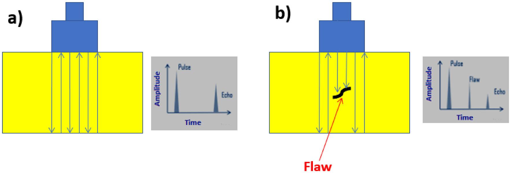
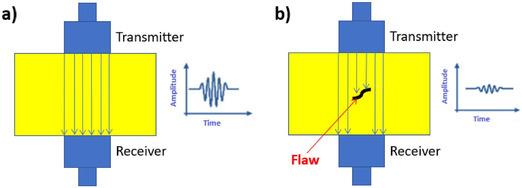
Lacerda, I. R. S., Costa, M. L., & Rezende, M. C.
Rus et al. investigated multiple ultrasonic techniques for the inspection of CF/epoxy laminates manufactured by the resin transfer molding process, inducing impact damages (15 J), according to ISO 18352[23]. The study compared different ultrasonic techniques: air-coupled ultrasonic (ACU), transmission with piezoelectric transducers (cPP), laser-induced ultrasonic, immersion testing, phased array ultrasonic testing (PAUT), and, finally, thermoacoustic emission (TAE). This study showed that. ACU is suitable for automated plate inspections, cPP provides high contrast and is cost-effective for large impact damage detection, laser-induced ultrasonic and immersion testing are recommended for high-sensitivity applications requiring superior spatial resolution, PAUT is ideal for single-sided inspection of thick composite parts but is challenging to automate, and TAE is capable of producing short pulses, offering the potential for single-sided ACU inspection with improved depth resolution.
Gonçalves et al. evaluated CF/epoxy laminates using three ultrasonic techniques: critically refracted longitudinal wave (LCR), B-scan phased array system, and total focusing method (TFM) signal-to-noise ratio (SNR) analysis[24] Their findings allowed them to conclude that the LCR was ineffective in identifying defect locations; B-Scan images accurately detected delaminations but struggled with fiber waviness detection, and SNR-TFM imaging successfully detected both delaminations and fiber misalignment.
Montagna et al.[4,25] manufactured CF/poly(phenylene sulfide) (PPS) laminates using semipreg scraps from the aerospace sector through hot compression molding processing and evaluated them by ultrasonic testing, using the phased array (PAUT, with a voltage of 40 V, at 5 MHz
of frequency and the images showed the presence of some voids, internal discontinuities, and some processing defects that may be due to the overlapping of CF/PPS semipreg scraps, as shown in Figure 4
Morgado et al.[26] used ultrasonic analyses to support the establishment of the processing cycle of CF/PPS laminates through hot compression molding. Based on the ultrasonic images, the authors established a reliable and repetitive processing cycle for this composite material.
Gomes et al.[2] used ultrasonic testing to evaluate GF/ poly(aril ether ketone) (PAEK) laminates with carbon nanotube buckypapers (BPs). Based on the ultrasonic images, the authors concluded that the consolidation of the reference’s laminate (without BPs) was not entirely uniform (Figure 5a). In the laminates with BPs (Figure 5b-e), the ultrasonic inspection indicates polymer accumulation in certain regions (red areas), BP location (reddish areas), as well as potential fractures and ruptures at the end of the BP films (bluish and greenish areas), probably caused by excessive pressure applied during consolidation step.
The studies from the literature show that ultrasonic testing is a versatile and widely used NDT method for detecting discontinuities in polymeric composites. This method is effective for identifying cracks, voids, and delaminations, but its accuracy depends on the material properties, discontinuity characteristics, and chosen ultrasonic method. Recent advancements in phased array and air-coupled techniques have enhanced resolution and automation potential, making UT a key tool for composite inspection in aerospace, automotive, and structural engineering applications.
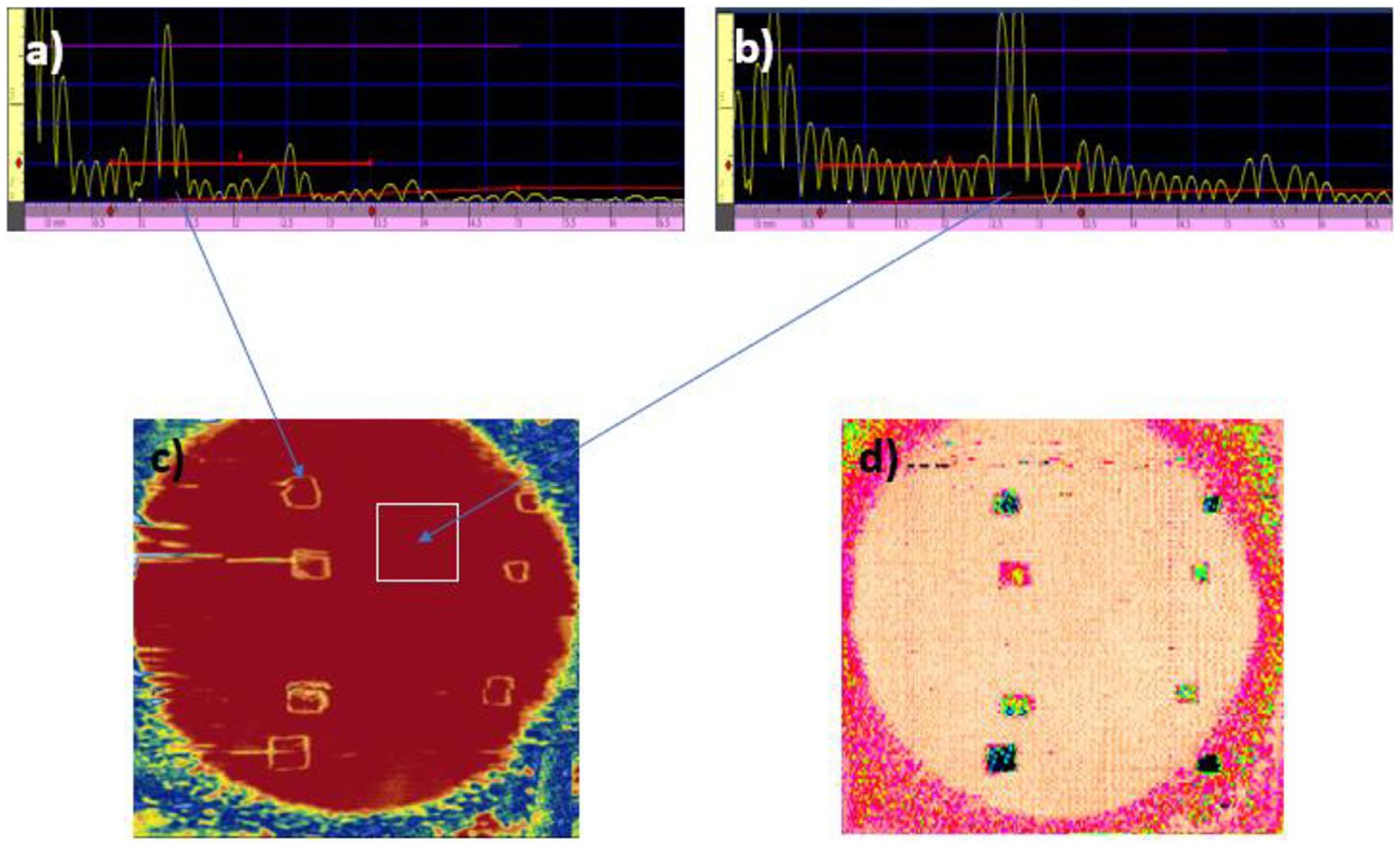
A review of non-destructive testing for polymeric composites: techniques, challenges, and advances
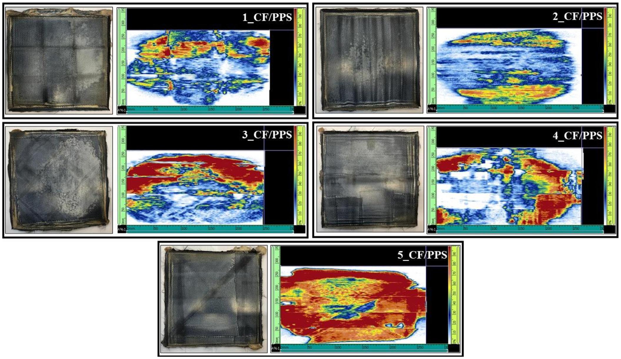
Figure 4. Ultrasonic images of CF/PPS laminates obtained with different scrap arrangements: Blue/white areas correspond to the presence (e.g., voids). Red/orange/yellow regions correspond to good consolidation, suggesting the absence of voids[25]
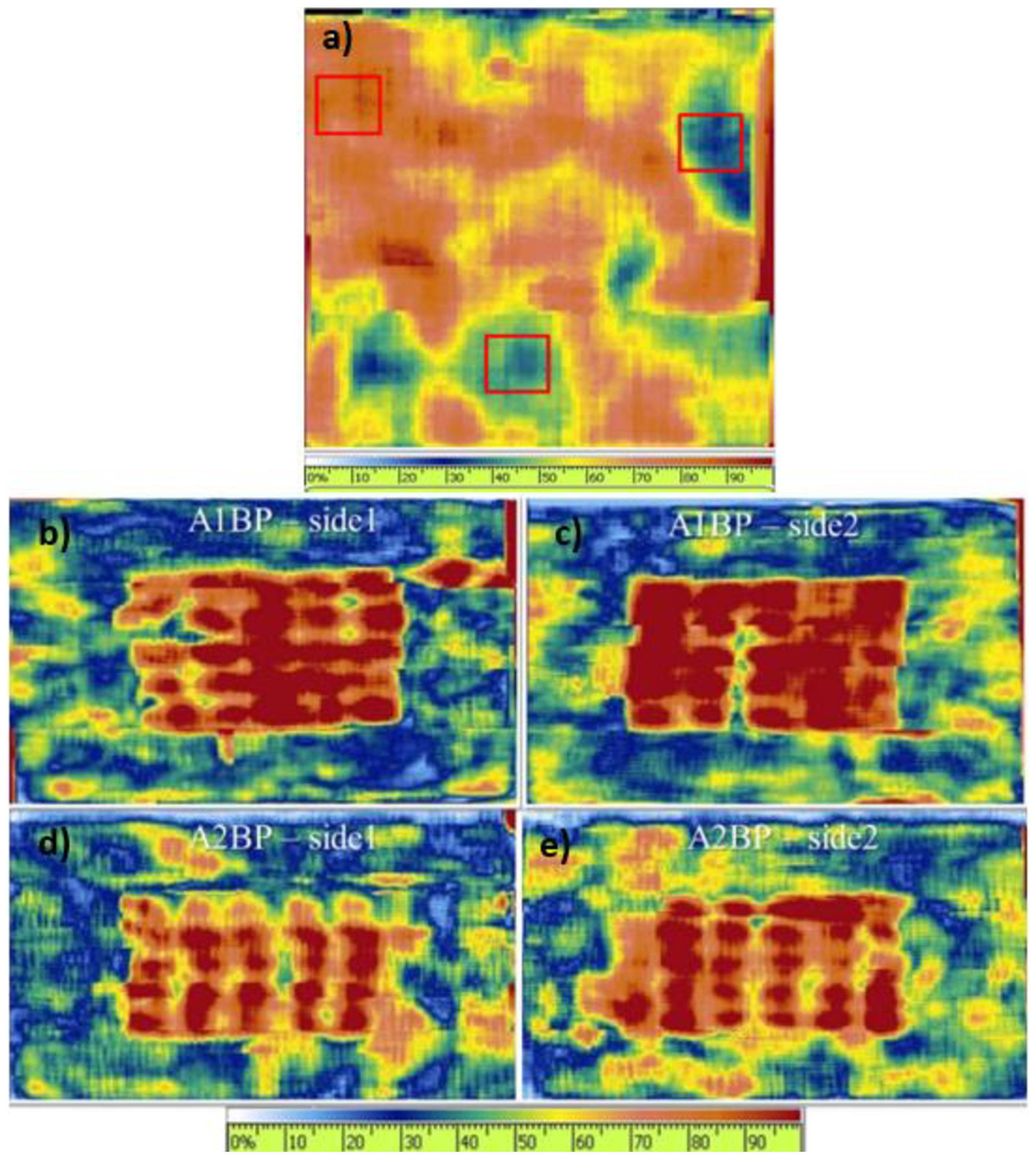
Lacerda, I. R. S., Costa, M. L., & Rezende, M. C.
X-ray testing is an NDT method that utilizes electromagnetic radiation to inspect materials for internal defects. When a material has non-uniform characteristics, such as variations in thickness, density, or chemical composition, it absorbs penetrating radiation at different rates. This difference in absorption allows the identification of failures or discontinuities within the structure[27,28]
The intensity of electromagnetic radiation passing through a material decreases exponentially with increasing material thickness, according to Equation 1[28-30]: ( ) ( ) ( ) 0 Ex
where:
E is the energy of the incident radiation;
I0 is the intensity of the radiation source;
I is the intensity of the radiation after passing through the material;
x is the material thickness;
µ is the total absorption coefficient of the material.
The total absorption coefficient is defined as the sum of the absorption coefficients of the material. Differences in density, thickness, and composition directly affect the intensity of the absorbed radiation and, consequently, the transmitted radiation. Therefore, discontinuities appear in radiographic images due to variations in radiation absorption between the defect and the surrounding material[28,29] .
The greater the density difference between a defect and the surrounding material, the higher the contrast in the radiographic image. This means that X-ray testing
sensitivity is directly proportional to object density and inversely proportional to the defect size[29]
When X-rays interact with a material, they can be absorbed, transmitted, or scattered. The absorbed fraction is detected by an image receptor, known as a detector, which can be either conventional or digital. Conventional radiography uses radiographic film, and the image development process is chemical and latent. On the other hand, digital radiography (flat panel detector) converts absorbed radiation into an electrical signal, generating a digital image displayed in real time on a computer screen[27] .
Similar to ultrasonic testing, X-ray investigation has a wide range of applications. Ferreira et al.[27] applied X-ray digital testing to evaluate laminated pipe joints in composite materials reinforced with CFs. The study successfully visualized the junction of ducts and the laminated layers. Additionally, the author introduced acetate tapes into the tubes to simulate delaminations and assess the detection sensitivity of the technique. While all tapes were detected, discrepancies were found between the actual defect sizes and those measured via X-ray imaging. Figure 6(a-f) shows a pipe joint X-ray digital image.
2.2.2 Challenges of X-ray inspection for polymeric composites
X-ray inspection is commonly applied to metallic materials, but its use in polymeric composites is limited when the difference in atomic weight of the materials, that is, among the phases of the composite material, is less pronounced. In other words, the X-ray interaction mechanisms are different for different materials[31 32]. So, the success of the use of this method includes two key challenges that is,
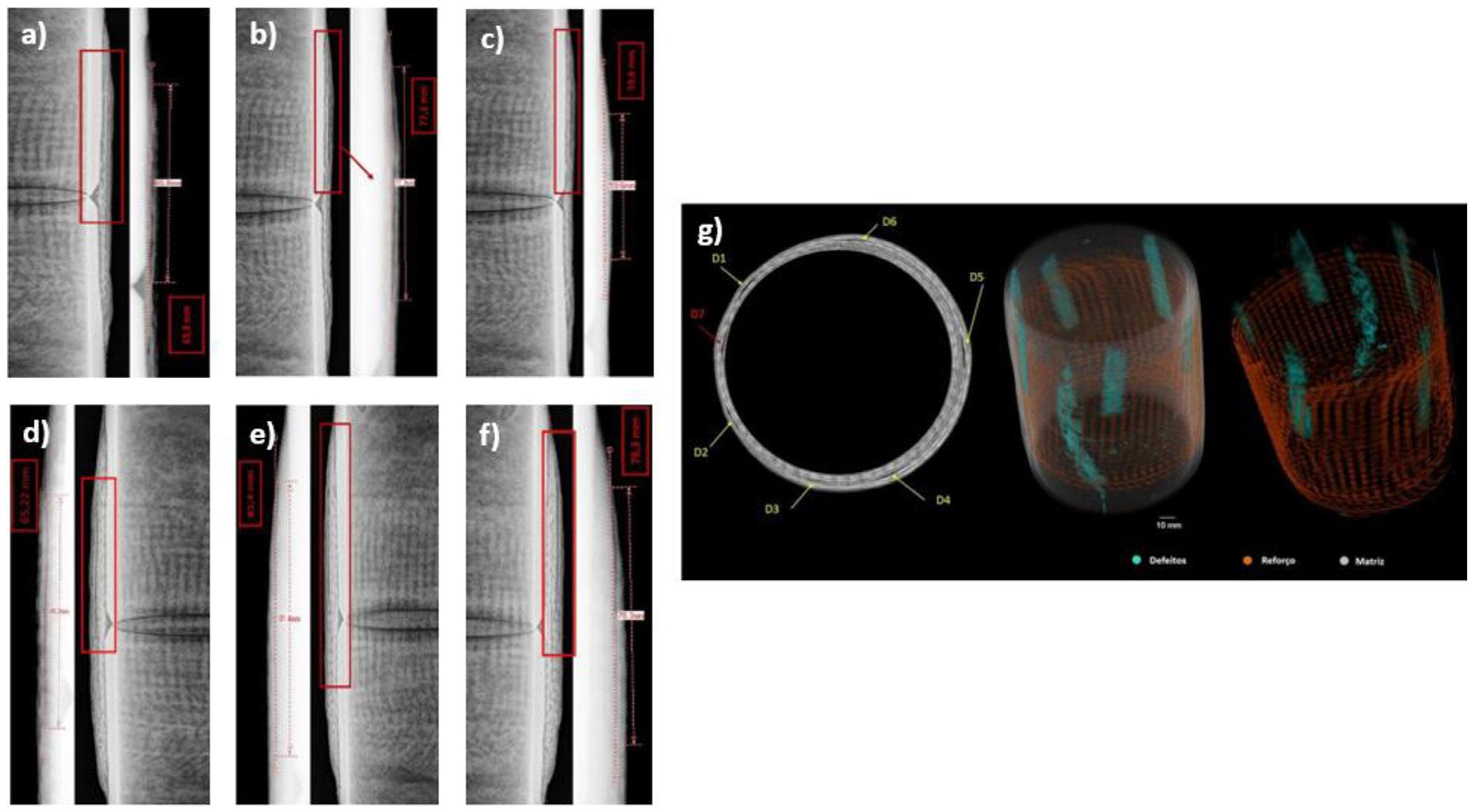
A review of non-destructive testing for polymeric composites: techniques, challenges, and advances
density and X-ray absorption. Knowing that metals have a higher density than polymeric composites, they absorb X-rays more efficiently, resulting in high-resolution images that reveal clearer cracks, porosities, and inclusions. On the other hand, polymeric composites, having lower density, absorb less radiation, producing low-contrast images, making defect detection more difficult.
X-ray imaging of metals provides high contrast between a defect and the surrounding material due to their higher atomic number and density. However, the contrast may be insufficient in polymeric composites, impairing the detection of small defects or internal variations, especially when the polymer matrix and fiber reinforcement (e.g., CF) have similar densities. Industrial applications of X-ray inspection of metallic materials are widely used, requiring high precision in defect detection, such as in aerospace and automotive manufacturing. Metals are often used in highstrength applications, where internal defects could lead to catastrophic failures, making radiographic testing essential.
Alternatives more effective for interface inspection and internal defect characterization of polymeric composites are UT and microcomputed tomography (microCT) inspections, considering that the X-rays cannot provide sufficient contrast and spatial resolution for some composite structures.
The use of X-ray techniques for polymeric composites monitoring has shown limited application due to the low density contrast and limited defect detectability. However, advancements in this area have allowed the X-ray application with good results. In this case, it can be cited that digital radiography, phase-contrast imaging, and microfocus X-ray methods improved the detection of discontinuities in polymeric composites.
Vavrik et al.[33] developed a phase contrast X-ray technique to detect closed delaminations in CF reinforced plastic (CFRP) composite. According to the authors, closed delaminations mean layers of delamination in contact, and the X-ray radiography projection cannot contribute to image formation by attenuation. In this study, the authors used a microfocus X-ray tube technique with a photon-counting energy-sensitive hybrid semiconductor pixel detector and a relatively large sample-to-detector distance. According to the authors, the best approach for detecting closed delaminations is to attenuate the image by performing two measurements using two different energy thresholds (5 and 16 keV) with the same experimental setup. This methodology is good because the absorption depends on the energy as 1/E4 and the refraction as 1/E2. In this way, the absorption contrast is strongly energy sensitive. With this approach, the authors identified and visualized closed delaminations successfully. For detecting open delaminations, meaning a physical gap between delaminated layers, high-resolution computed tomography techniques may be used. However, there is an experimental challenge once the volume of the open delamination is relatively small and the local density varies by several hundred percent. Therefore, the contrast and spatial resolution are very high. For this analysis, the authors used a high-resolution setup based on a micro-focus X-ray tube
and an appropriate beam-hardening calibration. Thus, open delaminations were successfully identified and visualized.
2.2.3.2
Rique et al.[34] applied a digital X-ray technique to evaluate bonded joints in GF-reinforced epoxy pipes, using three types of samples: one without defects (control samples), samples with insufficient adhesive, and samples with poor adhesion. The results showed that the control samples showed voids in high-contrast regions; samples with low adhesive content had minimal voids, likely due to reduced thickness, allowing greater radiation transmission, and the ones with poor adhesion exhibited small voids. However, the gap between the adhesive layer and pipe wall was not visible clearly, indicating the limited effectiveness of X-ray for this type of defect.
2.2.3.3
Anoshkin et al. analyzed CF/epoxy straightener blades using microfocus X-ray technology[35]. A radiation source with a focal spot size of <100 µm was used to detect interlayer delaminations, pores, and wrinkles. According to the authors, the studied polymeric composites have close density values (reinforcing element and polymeric matrix), resulting in low-contrast images, reducing the probability of detection and identification of discontinuities by traditional radiography techniques. Thus, the microfocus X-ray technique can obtain informative X-ray images with a lower radiation load compared to the traditional X-ray technique. In the study, Anoshkin and collaborators used a microfocus X-ray machine with an anode voltage of less than 130 kV, an anode current of less than 200 µA, and a focal spot size ranging from 20 to 100 µm[35]. The authors concluded that the microfocus X-ray technique allows the inspection of the bending of layers from blades, which means inaccessible areas for other non-destructive testing methods. The inspection time does not exceed 1 minute, and the total analysis time is around 5 - 7 minutes.
Thus, while X-ray testing is a valuable NDT for metallic materials, its application to polymeric composites remains challenging due to the low density contrast and limited defect detectability. However, advancements in digital radiography, phase-contrast imaging, and microfocus X-ray have improved defect visualization in polymeric composites. In many cases, combining X-ray with other NDT methods, such as ultrasonic or microcomputed tomography (microCT), increases reliability, ensuring better defect characterization in critical applications.
Traditional X-ray radiographic equipment allows the evaluation of materials on a two-dimensional (2D) scale. However, 2D imaging does not provide depth information, making it difficult to determine precisely the position and extent of internal discontinuities. In contrast, microCT generates high-resolution three-dimensional (3D) X-ray images, allowing a detailed evaluation of microstructure and morphology[27,36] .
The microCT reconstructs X-ray transmission data from multiple 2D projections to create cross-sectional images of
Lacerda, I. R. S., Costa, M. L., & Rezende, M. C.
the sample, eliminating interference from overlying and underlying structures[17,27,36]
The quality of the images obtained via microCT depends on the material density, atomic number, and X-ray beam energy. This technique offers high sensitivity, even in cases where density differences between structures are minimal (< 1%)[17,37,38] . Figure 7 illustrates examples of 2D and 3D X-ray imaging.
The microCT systems are classified based on the shape of the incident X-ray beam[39] as Fan Beam Computed Tomography (FBCT) and Cone Beam Computed Tomography (CBCT). Figure 8 presents examples of CBCT and FBCT imaging techniques.
Rique et al.[34] employed microCT to analyze voids in bonded joints made from GF-reinforced epoxy resin. The study demonstrated that voids compromise adhesion, potentially leading to mechanical failure. The authors aimed to develop inspection methodologies to identify and quantify defects in bonded regions. MicroCT allowed the measurement of void volume, size, shape, and distribution, as well as the anisotropic characteristics of the microstructure of the bonded joints. The results confirmed that microCT effectively detected adhesion failures and impurities within the adhesive layer.
Ferreira et al.[27] evaluated laminated pipe joints made of carbon fiber-reinforced composites, comparing X-ray radiography and microCT. The study found that certain discontinuities were undetectable via conventional X-ray imaging but identified through microCT. The improved defect
detection using the microCT method was attributed to its smaller focal spot size, which enhances spatial resolution, providing superior imaging of internal structures. So, microCT has been shown to be a powerful NDT tool for 3D imaging of polymeric composites, offering high resolution and precise defect characterization. Unlike traditional 2D radiography, microCT enables the detection of voids, delaminations, and adhesion failures with improved depth resolution. Due to its ability to reconstruct detailed internal structures, microCT is increasingly applied in composite materials research, failure analysis, and quality control. Figure 6g presents the difference between X-ray radiography (2D) and microCT (3D) for the same sample of polymeric composite, that is, a pipe joint made in CF-reinforced composite material containing acetate strips.
Thermography testing is an NDT method that enables the inspection of large areas in relatively short periods. This technique is widely used to assess impact damage and to detect delaminations in composite materials[40-42]. It is particularly advantageous for inspecting complex geometries and bonded joints between similar or dissimilar materials. Additionally, thermographic testing can be performed from a single side of the structure, making it a fast and practical inspection method[17,40,41]
Any object with a temperature above absolute zero (0 K) emits thermal radiation, most of which falls within the infrared spectrum. Thermographic cameras are designed
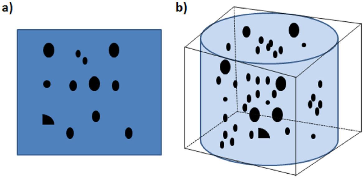
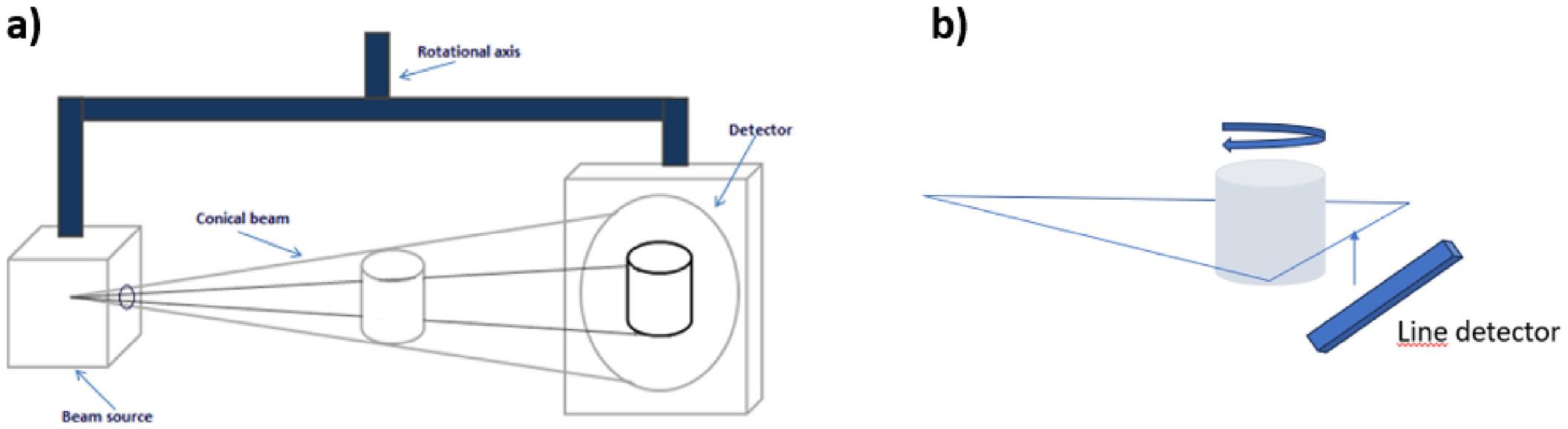
A review of non-destructive testing for polymeric composites: techniques, challenges, and advances
to detect infrared radiation emitted by the inspected object and convert it into a visible thermal image[43]
According to the radiation law, when an object is exposed to thermal radiation, it exhibits three key radiative properties: a) absorbance, when a fraction of the incident radiation is absorbed by the material, b) reflectance, when a fraction of radiation is reflected by the surface of material and c) transmittance, when a fraction of radiation passes through the material. For opaque materials, the transmittance is zero, meaning that the sum of absorption and reflection is equal to one[43]
The thermographic inspection method can be classified into two main categories that is, passive thermography and active thermography[41,43,44]. In the first technique, the test object naturally emits infrared radiation, without external heat application, and it is commonly used in predictive maintenance and structural health monitoring. The latter involves an external energy source (e.g., flash lamps or lasers) that heats the material, and the thermal diffusion is analyzed. This technique is used in non-destructive evaluation to detect subsurface defects[41,42,44,45] Figure 9 schematically shows the difference between active and passive thermography.
In active thermography, localized heat diffusion is affected by internal defects, causing temperature variations on the surface of the material. Defective regions exhibit different thermal behavior compared to defect-free areas, enabling the quantification of internal damage[17,41,44-46] .
2.4.2
Emissivity is the characteristic of a material to emit thermal radiation at a given temperature. Kirchhoff’s Law states that the absorption capacity of a material is equal to its emission capacity at the same wavelength. The amount of radiation emitted by an object is directly proportional to its emissivity and temperature. Low-emissivity materials (e.g., polished metal surfaces) emit less radiation, making thermographic testing more challenging[43]
Several factors influence emissivity, including a) surface condition, knowing that polished surfaces reflect
more infrared radiation, reducing emissivity; b) material composition (different materials have distinct emissivity values), and viewing angle, which affects the image clarity and must be considered in result interpretation[41]
Several studies have demonstrated the effectiveness of thermographic techniques in detecting defects in fiber-reinforced polymer (FRP) composites. Santiago (2019) employed principal component thermography and pulsed phase thermography to inspect carbon fiberreinforced polymer (CFRP) composites [47]. Based on the signal-to-noise ratios, the study concluded that the principal component thermography provided higher defect visualization accuracy.
Pscheidt used thermography to detect discontinuities in epoxy-based CFRP laminates[48]. The author manufactured samples with induced defects (30 mm and 50 mm in size) and heated them by immersion in water at 30, 40, and 50 °C until thermal equilibrium was reached. After removal from the water, thermal images were captured. The results showed that defects were detectable at all temperatures, but 40 °C provided the highest thermal contrast, making defects more visually distinguishable.
Luo et al.[49] explored stepped heating and lock-in thermography to inspect CFRP composites used in railway components. The study confirmed that the technique was effective in detecting defects up to 10 mm in depth in complex composite structures. Tromaras and Kappatos[50] and Zhang et al.[51] demonstrated that thermographic techniques are highly effective for subsurface defect detection in CFRP and GFRP composites[50,51]. Luo et al.[49] also applied thermography to hybrid CFRP/PET/CFRP sandwich composites and confirmed its ability to identify defects in surface and subsurface layers, even in low-emissivity materials.
Thermographic inspection is a powerful NDT technique for evaluating polymeric composites, particularly in detecting delaminations, impact damage, and subsurface defects. While passive thermography is useful for monitoring temperature variations over time, active thermography enhances defect detection through controlled heat diffusion
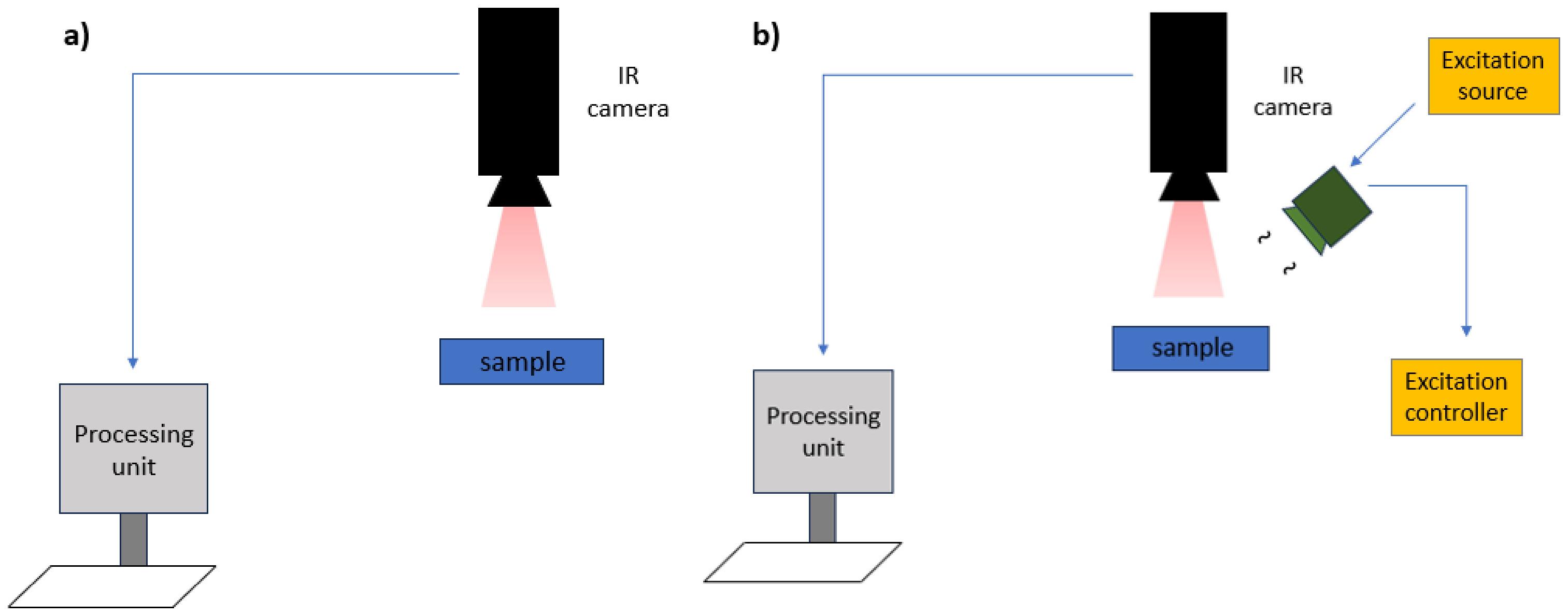
I. R. S., Costa, M. L., & Rezende, M. C.
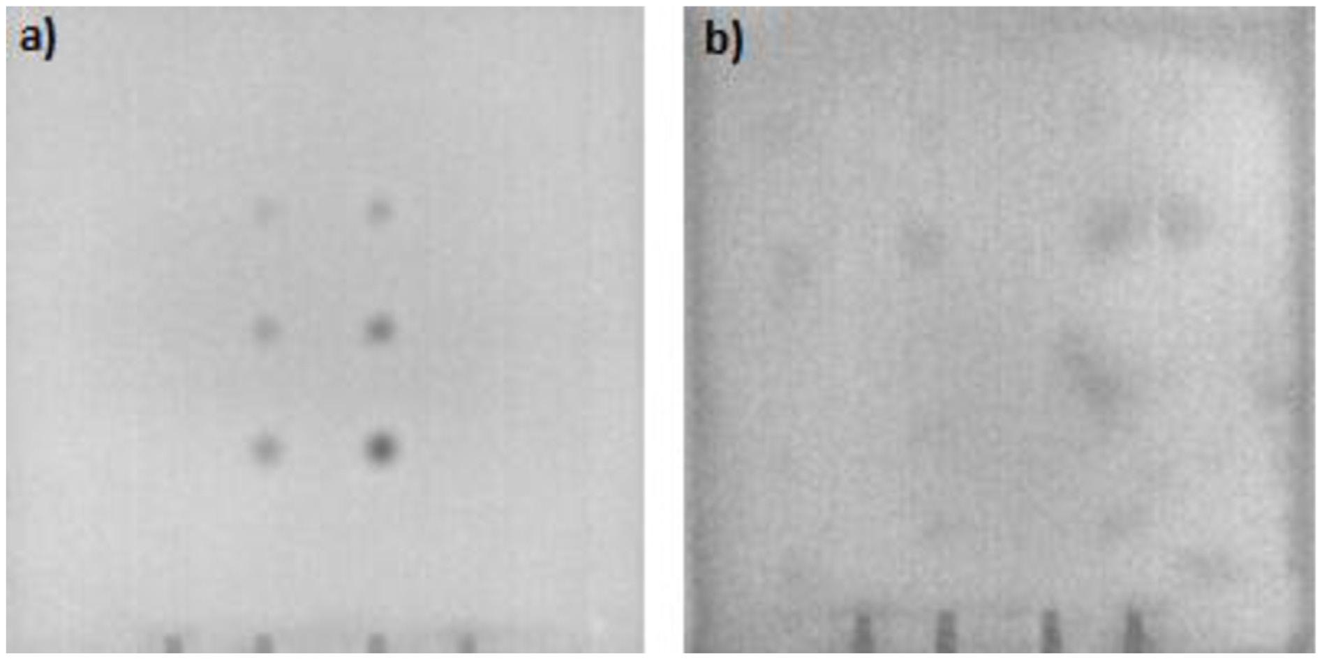
Table 1. Comparison of the main non-destructive testing (NDT) methods applied to polymeric composites, highlighting their principles, detectable defects, advantages, limitations, and typical applications.
NDT Method Working Principle Detectable Defects Advantages Limitations
Ultrasonic Testing (UT) High-frequency sound wave propagation
Delaminations, cracks, voids, internal discontinuities
High sensitivity, portable, relatively low cost
Requires a coupling medium, complex interpretation, limited to irregular geometries
X-ray Testing (XR)
Microcomputed Tomography (microCT)
Thermography (Active/ Passive)
Radiation attenuation by density and thickness
3D reconstruction from multiple X-ray projections
Detection of infrared radiation emitted by the sample
Voids, delaminations, inclusions
Voids, delaminations, adhesion failures, microcracks
Delaminations, impact damage, interfacial debonding
analysis. This technique is especially effective for complex geometries and hybrid composite structures, making it a valuable tool for aerospace, automotive, and railway applications. Figure 10 presents images of CF/poly(ether imide) (PEI) laminates evaluated by active thermography. This NDT technique allowed determining the presence of the discontinuities in the CF/PEI laminates, but the resolution is limited.
A comparative overview of the main non-destructive testing methods applied to polymeric composites is summarized in Table 1, providing a concise visualization of their operational principles, capabilities, and limitations.
This review provided a comprehensive and critical overview of non-destructive testing (NDT) techniques applied to polymeric composites, highlighting their capabilities and limitations in detecting manufacturing and service-induced defects. Among the methods discussed, ultrasonic testing (UT) demonstrated high sensitivity to internal discontinuities, while X-ray techniques and microCT offered superior spatial
Fast 2D imaging, wellestablished for metals
High resolution, 3D visualization, defect quantification
Fast, contactless, suitable for complex geometries
Low contrast in composites, limited resolution for small defects
Expensive equipment, time-consuming, and a limited sample size
Affected by surface emissivity, limited depth resolution
Typical Applications
Aerospace, automotive, energy
Joint inspection, tubes, flat structures
Research, failure analysis, process validation
Predictive maintenance, structural monitoring
resolution for internal defect characterization. Thermography, in turn, proved effective for identifying surface and subsurface anomalies, especially in complex geometries, particularly in detecting delaminations and impact damage.
The comparative analysis reveals that no single NDT technique is universally sufficient to detect all types of defects in polymeric composites. Therefore, hybrid approaches, combining two or more NDT techniques, are encouraged to enhance accuracy and reliability in critical applications.
Based on the state-of-art in the NDT area, it is suggested for future researches to focus on a) the integration of complementary NDT methods for more complete damage assessment; b) the development of AI-based image processing tools to automate defect detection and improve analysis speed, and c) the standardization of inspection protocols to ensure consistency and reproducibility across different industries.
By providing a structured comparison and practical insights, this study contributes to advancing NDT practices in polymeric composites and supporting safer and more efficient applications in aerospace, automotive, and energy sectors.
4. Author’s Contribution
• Conceptualization – Ingrid Regina dos Santos Lacerda.
• Data curation – Ingrid Regina dos Santos Lacerda.
• Formal analysis – Ingrid Regina dos Santos Lacerda; Michelle Leali Costa; Mirabel Cerqueira Rezende.
• Funding acquisition – Mirabel Cerqueira Rezende.
• Investigation – Ingrid Regina dos Santos Lacerda.
• Methodology – Ingrid Regina dos Santos Lacerda; Michelle Leali Costa; Mirabel Cerqueira Rezende.
• Project administration – Ingrid Regina dos Santos Lacerda; Michelle Leali Costa; Mirabel Cerqueira Rezende
• Resources – Mirabel Cerqueira Rezende.
• Software – NA.
• Supervision – Michelle Leali Costa; Mirabel Cerqueira Rezende.
• Validation – Ingrid Regina dos Santos Lacerda; Michelle Leali Costa; Mirabel Cerqueira Rezende.
• Visualization – Ingrid Regina dos Santos Lacerda; Michelle Leali Costa; Mirabel Cerqueira Rezende.
• Writing – original draft – Ingrid Regina dos Santos Lacerda.
• Writing – review & editing – Ingrid Regina dos Santos Lacerda; Michelle Leali Costa; Mirabel Cerqueira Rezende.
5. Acknowledgements
The authors are grateful to the National Council for Scientific and Technological Development (CNPq) (304876/2020-8 and 306836/2023-8) for the financial support.
6. References
1 Dilonardo, E., Nacuchi, M., De Pascalis, F., Zarrelli, M., & Giannini, C. (2022). Inspection of carbon fibre reinforced polymers: 3D identification and quantification of components by X-ray CT. Applied Composite Materials, 29(2), 497-513 https://doi.org/10.1007/s10443-021-09976-x
2 Gomes, J. V. P. N., Costa, M. L., Thomazini, D., Santos, L. F. P., Ribeiro, B., & Botelho, E. C. (2024). Impact of stacking sequence on the thermal and electrical properties of Poly (aryl ether ketone)/glass fiber/buckypaper composites. Journal of Applied Polymer Science, 141(39), e55996. https://doi. org/10.1002/app.55996
3 Marques, T. P. Z., Mayer, S., Candido, G. M., & Rezende, M. C. (2021). Fractographic analysis of scarf repaired carbon/ epoxy laminates submitted to tensile strength. Engineering Failure Analysis, 124, 105374 https://doi.org/10.1016/j. engfailanal.2021.105374
4. Montagna, L. S., Morgado, G. F. M., Marini, J., Guimarães, A., Passador, F. R., & Rezende, M. C. (2023). Mechanical properties of carbon fiber/PPS laminates processed by hot compression molding under different consolidation cycles. Polymer Composites, 44(6), 3358-3371 https://doi.org/10.1002/pc.27326
5 Rezende, M. C., & Botelho, E. C. (2000). O uso de compósitos estruturais na indústria aeroespacial. Polímeros: Ciência e Tecnologia, 10(2), E4-E10. https://doi.org/10.1590/S010414282000000200003
6 Department of Defense of USA. (2002). Composite materials handbook (Vol. 1: Polymer matrix composites: Guidelines for
characterization of structural materials (MIL-HDBK-17-1F)) Retrieved in 2025, August 2, from https://apps.dtic.mil/sti/tr/ pdf/ADA426516.pdf
7 Conejo, L. S., Santos, L. F. P., Ribeiro, B., Kok, W., Warnet, L., Costa, M. L., & Botelho, E. C. (2022). Reconsolidation effect on impact, compression after impact, and thermal properties of poly (aryl ether ketone) composites for aeronautical applications. Journal of Thermoplastic Composite Materials, 36(6), 25622581 https://doi.org/10.1177/08927057221102854
8 Marshall, A. C. (1987). Composite structures in home-built sport aircraft. In Proceedings of the 32nd International Sampe Symposium USA
9 Paiva, J. M. F., Hosokawa, M. N., Montagna, L. S., & Rezende, M. C. (2024). Effect of hygrothermal conditioning on compressive strength after impact in carbon fiber/epoxy composites. Journal of Applied Polymer Science, 141(16), e55237 https://doi.org/10.1002/app.55237
10 Rahman, M. S. U., Hassan, O. S., Mustapha, A. A., Abou-Khousa, M. A., & Cantwell, W. J. (2023). Inspection of thick composites: a comparative study between microwaves, x-ray computed tomography and ultrasonic testing. Nondestructive Testing and Evaluation, 39(7), 2054-2071 https://doi.org/10.1080/1058975 9.2023.2287071
11. Silva, T. C., Moraes, D. V. O., Morgado, G. F. M., Gonçalves, V. O., Costa, D. H. S., Marques, T. P. Z., Passador, F. R., & Rezende, M. C. (2022). Mechanical characterization and fractographic study of the carbon/PEI composite under static and fatigue loading. Mechanics of Advanced Materials and Structures, 31(6), 12911299 https://doi.org/10.1080/15376494.2022.2134952
12 Toray Advanced Composites. (2024). TC1000-Premium PDS v4 (2020-12-17). Retrieved in 2025, August 2, from https:// www.toraytac.com/product-explorer/products/uHNz/TorayCetex-TC1000-Premium
13 Wang, B., Zhong, S., Lee, T.-L., Fancey, K. S., & Mi, J. (2020). Non-destructive testing and evaluation of composite materials/structure: a state-of-the-art review. Advances in Mechanical Engineering, 12(4), 1687814020913761 https:// doi.org/10.1177/1687814020913761
14 Hsissou, R., Seghiri, R., Benzekri, Z., Hilali, M., Rafik, M., & Elharfi, A. (2021). Polymer composite materials: a comprehensive review. Composite Structures, 262, 113640 https://doi.org/10.1016/j.compstruct.2021.113640.
15 Zimmermann, N., & Wang, P. H. (2020). A Review of Failure Modes and Fracture Analysis of Aircraft Composite Materials. Engineering Failure Analysis, 115 , 104692 https://doi. org/10.1016/j.engfailanal.2020.104692
16 Hudson, T. B., Baro, F., Smith, A. J., Kang, J. H., Cano, R. J., & Palmieri, F. L. (2023). Ultrasonic inspection during autoclave cure of reflowable-interface composite joints. Journal of Composite Materials, 57(22), 3515-3528 https:// doi.org/10.1177/00219983231188173
17 International, A. S. M. (1989). ASM handbook (Vol. 17: Nondestructive evaluation and quality control). Materials Park: ASM International
18 Zilidou, M., Smith, R. A., & Wilcox, P. D. (2022). Suppression of front and back surface reflections in ultrasonic analyticsignal responses from composites. Ultrasonics, 126, 106815 https://doi.org/10.1016/j.ultras.2022.106815 PMid:35933809.
19. Costa, M. L., Rezende, M. C., & Almeida, S. F. M. (2005). Strength of hygrothermally conditioned polymer composites with voids. Journal of Composite Materials, 39(21), 1943-1961 https://doi.org/10.1177/0021998305051807
20 Costa, M. L., Almeida, S. F. M., & Rezende, M. C. (2005). Critical void content for polymer composite laminates. AIAA Journal, 43(6), 1336-1341 https://doi.org/10.2514/1.5830
Lacerda, I. R. S., Costa, M. L., & Rezende, M. C.
21 Melo, R. R., & Del Menezzi, C. H. S. (2016). Estimativas das propriedades físico-mecânicas de compostos LVL confeccionados com paricá por meio de ultrassom. Ciência Florestal, 26(1), 263-272 https://doi.org/10.5902/1980509821118
22 Smagulova, D., & Jasiuniene, E. (2018). Inspection of dissimilar material joints using ultrasonic phased arrays. Elektronika ir Elektrotechnika, 24(6), 28-32 https://doi.org/10.5755/j01. eie.24.6.22286
23 Rus, J., Gustschin, A., Mooshofer, H., Grager, J.-C., Bente, K., Gaal, M., Pfeiffer, F., & Grosse, C. U. (2020). Qualitative comparison of non-destructive methods for inspection of carbon fiber-reinforced polymer laminates. Journal of Composite Materials, 54(27), 4325-4337 https://doi.org/10.1177/0021998320931162
24 Gonçalves, V. V., Oliveira, D. M. G., & Santos, A. A., Jr (2021). Comparison of ultrasonic methods for detecting defects in unidirectional composite material. Materials Research, 24(suppl. 2), e20210323. https://doi.org/10.1590/1980-5373mr-2021-0323
25 Montagna, L. S., Morgado, G. F. M., Marini, J., Guimarães, A., Ferro, O., Passador, F. R., & Rezende, M. C. (2025). End-of-life carbon fiber/poly(phenylene sulfide) semipreg scraps from the aerospace industry: towards a sustainable product. Next Materials, 6, 100396 https://doi.org/10.1016/j. nxmate.2024.100396
26 Morgado, G. F. M., Montagna, L. S., Gouvêa, R. F., Guimarães, A., Passador, F. R., & Rezende, M. C. (2023). Fatigue and durability assessment of PA6-based carbon fiber composites for lightweight applications. Journal of Composite Materials, 57(27), 4227-4238 https://doi.org/10.1177/00219983231207148
27 Ferreira, C. G., Lopes, R. T., Santos, T. M. P., Oliveira, D. F., Martins, F. D. F., & Pereira, G. R. (2018). Non-destructive inspection of laminated pipe joints in polymeric composite material reinforced by fiberglass. Nuclear Instruments & Methods in Physics Research. Section A, Accelerators, Spectrometers, Detectors and Associated Equipment, 954, 161154 https:// doi.org/10.1016/j.nima.2018.08.113
28 Oliveira, D. F., Nascimento, J. R., Marinho, C. A., & Lopes, R. T. (2015). Gamma transmission system for detection of scale in oil exploration pipelines. Nuclear Instruments & Methods in Physics Research. Section A, Accelerators, Spectrometers, Detectors and Associated Equipment, 784, 616-620 https:// doi.org/10.1016/j.nima.2014.11.030
29 Ibragimov, R., Korolev, E., Deberdeev, T., & Dolbin, I. (2022). Influence of electromagnetic radiation on the degradation of reinforced concrete structures - review. Case Studies in Construction Materials, 17, e01454 https://doi.org/10.1016/j.cscm.2022. e01454
30 Souza, M. A. M., Pardini, L. C., Botelho, E. C., & Costa, M. L. (2019). X-ray tomography applied to the void/defect measurement of hybrid CFRC/SiC composites. Materials Research Express, 6(4), 045606 https://doi.org/10.1088/20531591/aaf90f
31 Chawla, K. K. (2019). Composite materials: science and engineering Switzerland: Springer https://doi.org/10.1007/9783-030-28983-6
32 Halmshaw, R. (1997). Introduction to the non-destructive testing of welded joints. Cambridge: Woodhead Publishing.
33 Vavrik, D., Jakubek, J., Jandejsek, I., Krejci, F., Kumpova, I., & Zemlicka, J. (2015). Visualization of delamination in composite materials utilizing advanced X-ray imaging techniques. Journal of Instrumentation : An IOP and SISSA Journal, 10(04), C04012 https://doi.org/10.1088/1748-0221/10/04/C04012
34 Rique, A. M., Machado, A. C., Oliveira, D., Lopes, R. T., & Lima, I. (2015). R. X-ray Imaging Inspection of Fiberglass Reinforced by Epoxy Composite. Nuclear Instruments & Methods in Physics Research. Section B, Beam Interactions with
Materials and Atoms, 349, 184-191 https://doi.org/10.1016/j. nimb.2015.03.003
35 Anoshkin, A. N., Osokin, V. M., Tretyakov, A. A., Potrakhov, N. N., & Bessonov, V. B. (2017). Application of operational radiographic inspection method for flaw detection of blade straightener from polymeric composite materials. Journal of Physics: Conference Series, 808(1), 012003 https://doi. org/10.1088/1742-6596/808/1/012003
36 Ferreira, C., Araujo, O. M., Machado, A., Oliveira, D., Pereira, G., & Lopes, R. (2025). MicroCT-based methodology for defect detection and analysis in GRFP tube Joints. e-Journal of Non-Destructive Testing, 30(2), 1435-4934 https://doi.org/10.58286/30759
37 Araujo, O. M. O., Bastos, J. S., Machado, A. S., Santos, T. M. P., Ferreira, C. G., Claro, A. P. R. A., & Lopes, R. T. (2018). MicroCT parameters for multimaterial elements assessment. Journal of Physics: Conference Series, 975(1), 012053 https:// doi.org/10.1088/1742-6596/975/1/012053
38 Ferreira, C. G., Lopes, R. T., Oliveira, D. F., Santos, T. M. P., Araujo, O. M. O., Martins, F. D. F., & Pereira, G. R. (2019). Morphological study of defects in laminated joints of composite materials using micro CT. e-Journal of Nondestructive Testing, 24(3), 1-5 https://doi.org/10.58286/23644
39. Scarfe, W. C., Farman, A. G., & Sukovic, P. (2006). Clinical applications of cone-beam computed tomography in dental practice. Journal - Canadian Dental Association, 72(1), 75-80 PMid:16480609.
40 Meola, C., Boccardi, S., Carlomagno, G. M., Boffa, N. D., Monaco, E., & Ricci, F. (2015). Nondestructive evaluation of carbon fibre reinforced composites with infrared thermography and ultrasonics. Composite Structures, 134, 845-853 https:// doi.org/10.1016/j.compstruct.2015.08.119
41. Holland, S. D., & Reusser, R. S. (2016). Material Evaluation by Infrared Thermography. Annual Review of Materials Research, 46(1), 287-303 https://doi.org/10.1146/annurevmatsci-070115-032014.
42 Steenackers, G., Peeters, J., & Janssens, K. (2018). Sublayer composition evaluation of Artwork using active thermography. In Proceedings of the 14th Quantitative InfraRed Thermography Conference (pp. 503-506). Berlin, Germany https://doi. org/10.21611/qirt.2018.049
43. Jacob, G., Iven, J., & Sujatha, S. (2023). Breast cancer detection: a comparative review on passive and active thermography. Infrared Physics & Technology, 134, 104932 https://doi. org/10.1016/j.infrared.2023.104932.
44 Ricci, M., Zito, R., & Laureti, S. (2024). Pseudo-noise pulsecompression thermography: A powerful tool for time domain thermography analysis. NDT & E International, 148, 103218. https://doi.org/10.1016/j.ndteint.2024.103218
45 Oswald-Tranta, B. (2025). Inductive thermography – review of a non-destructive inspection technique for surface crack detection. Quantitative Infrared Thermography Journal, 22(5), 478-502 https://doi.org/10.1080/17686733.2024.2448049
46 Badghaish, A. A., & Fleming, D. C. (2008). Non-destructive inspection of composites using step heating thermography. Journal of Composite Materials, 42(13), 1337-1357 https:// doi.org/10.1177/0021998308092202
47 Santiago, L. M. S. (2020). Aplicação de técnicas de processamento de imagens de termografia infravermelha na inspeção de materiais compósitos reforçados com fibra de carbono (Undergraduate thesis). Universidade Federal de Uberlândia, Uberlândia
48 Pscheidt, L. F. (2022). Termografia Aplicada na Detecção de Defeitos em Compósitos de Fibra de Carbono e Resina Epóxi (Undergraduate thesis). Universidade Federal de Santa Catarina, Joinville
49 Luo, Z., Wang, H., Huang, Y., Shen, P., Zheng, E., & Zhang, H. (2024). Nondestructive detection of CFRP subsurface defects
A review of non-destructive testing for polymeric composites: techniques, challenges, and advances
using transient lock-in thermography. Journal of Thermal Analysis and Calorimetry, 150(11), 8229-8239 https://doi. org/10.1007/s10973-024-13130-7
50 Tromaras, A., & Kappatos, V. (2022). Exploring step-heating and lock-in thermography NDT using one-sided inspection on low-emissivity composite structures for new rail carbodies. Sensors (Basel), 22(21), 8195 https://doi.org/10.3390/s22218195 PMid:36365893.
51 Zhang, X., He, Y., Chady, T., Tian, G., Gao, J., Wang, H., & Chen, S. (2019). CFRP impact damage inspection based on
manifold learning using ultrasonic induced thermography. IEEE Transactions on Industrial Informatics, 15(5), 2648-2659 https://doi.org/10.1109/TII.2018.2866413
Received: Aug. 02, 2025
Accepted: Nov. 14, 2025
Editor-in-Chief: Sebastião V. Canevarolo
Jorge Braulio Amaya1* and Paola Duque Sarango1
1Ingnieria Ambiental, Laboratorios de Ciencias de La Vida, Universidad Politécnica Salesiana, Cuenca, Azuay, Ecuador
*jamaya@ups.edu.ec
Obstract
Plastic pollution caused by synthetic polymers is a global concern demanding environmentally friendly alternatives. This study presents the development of a thermoformable bioplastic composed of shrimp-derived chitin, corn starch, sugarcane bagasse, glycerol, and acetic acid, integrated with polyethylene terephthalate (PET) and maleic anhydride as a compatibilizer. The composite underwent mechanical, thermal, and biodegradability assessments. The formulation containing 5% chitin achieved a tensile strength of 0.833 MPa and a density of 2780 Kg/cm 3, highlighting its mechanical viability. Under controlled composting conditions, degradation was observed in 120 days. Although the primary polymer matrix consists of petroleum-based PET, the term “bioplastic” is justified by the presence of renewable constituents and proven biodegradability, following the definition by European Bioplastics. This structure supports partial replacement of fossil-derived plastics while promoting sustainable waste management. The study underscores the potential of integrating agro-industrial residues into polymeric systems aimed at contributing to circular economy in material science.
Keywords: bioplastic, biodegradability, chitin, extraction.
Data Ovailability: Research data is available upon request from the corresponding author.
How to cite: Amaya, J. B., & Sarango, P. D. (2026). Sustainable bioplastics based on shrimp chitin: Mechanical characterization and biodegradability evaluation. Polímeros: Ciência e Tecnologia , 36 (1), e20260001. https://doi.org/10.1590/0104-1428.20250019
The environmental challenges posed by plastics derived from petroleum have reached critical levels, positioning them as one of the most significant ecological threats of the 21st century. Recent data indicates that global plastic production hit 400 million tons in 2022, with a mere 9% being recycled[1 2]. This extensive accumulation predominantly impacts marine ecosystems, where plastics constitute 80% of solid waste, thereby exacerbating biodiversity loss and inducing chemical changes in oceanic environments. In light of this situation, bioplastics have emerged as a viable alternative, offering functional properties akin to traditional plastics while also being biodegradable and renewable[3-5] Notably, biopolymer-based materials such as chitin have shown promise in addressing plastic pollution[1 6]. Chitin, a polysaccharide found in the exoskeletons of crustaceans, represents a renewable resource with significant potential for sustainable applications[7-9]. Its chemical characteristics, particularly the presence of amino groups, render it a versatile candidate for the production of biodegradable bioplastics[9-12]. In Ecuador, the shrimp industry generates around 1.5 million tons of shrimp shells annually, presenting a unique opportunity to merge waste valorization with the creation of sustainable materials[13-16]
Nonetheless, its application in industry encounters notable hurdles, such as elevated production costs, complicated
extraction processes, and limitations regarding the mechanical strength of the resulting plastics[17,18]. Nevertheless, the industrial adoption of chitin faces considerable obstacles, including elevated production costs, complex extraction processes, and limitations in the mechanical properties of the resulting plastics [19,20]. Current research endeavors are directed towards optimizing extraction techniques and integrating chitin with other natural polymers, such as starch and sugarcane bagasse, to enhance both the physical properties and overall performance of the materials [9 21 22]
The term “bioplastics” is used throughout this study in accordance with the definition by European Bioplastics, which includes materials that are biobased, biodegradable, or both. Although the composite includes petrochemical PET as the primary matrix, the incorporation of renewable components and the demonstrated biodegradability under composting conditions support the use of this terminology.
In this work, we aim to develop a thermoformable bioplastic using chitin extracted from shrimp exoskeletons and evaluate its feasibility. The specific objectives of this study are to optimize chitin extraction methods, formulate a competitive bioplastic, and characterize its mechanical, thermal, and biodegradability properties.
2.1 Exoskeleton cleaning
In terms of exoskeleton preparation, 6 kg of shrimp exoskeletons from the CRAMAGROMAR company in Guayaquil, Ecuador, were employed for chitin extraction. The initial step involved cleaning the shells to remove any residual meat and contaminants. The cleaned shells were then dried in an oven at 90 °C for 5 hours until they reached a constant weight. Subsequently, the material was processed using a Polymix PX-MFC 90D mill to achieve a particle size of 300 microns, as indicated in the literature[23,24].
2.2 Obtaining chitin
The initial phase of the study concentrated on the extraction of chitin, utilizing shrimp exoskeletons as the primary source material. A 10% hydrochloric acid solution was employed to break down the shrimp exoskeletons, and this solution was maintained at a temperature of 37 °C for a duration of 12 hours.
2.3 Demineralization, deproteinization and discoloration
The exoskeleton, underwent a treatment process involving a 15% (v/v) acetic acid solution at ambient temperature for a duration of three hours, accompanied by agitation at 10 rpm. Following this, the material was subjected to vacuum filtration, rinsed three times with deionized water, and subsequently dried in an oven at 60 °C for six hours. A deproteinization step was then implemented utilizing proteolytic enzymes, specifically papain at an enzyme-tosubstrate ratio (E/S) of 0.5:100 and chymotrypsin at an E/S ratio of 0.7:100, with continuous agitation at 140 rpm for three hours at 40 °C, maintaining pH levels of 8.7 and 8, respectively, to effectively decompose the proteins present in the peel. The decolorization process was executed using 96% ethanol at a 1:20 ratio under constant agitation, followed by washing with deionized water to eliminate pigments. The absorbance of the sample was subsequently measured using a UV-Vis spectrophotometer at 470 nm. Upon completion of these procedures, the resultant material was dried once more at 60 °C for six hours, yielding a purified chitin.
Industrial cornstarch (Zea mays) served as a starch source and functioned as the foundational plasticizer for the blend. To enhance the rigidity and durability of the bioplastic, sugarcane
cellulose was incorporated. The collected bagasse underwent disinfection, was air-dried, and then ground into a fine powder. Subsequently, it was subjected to hydrolysis using sulfuric acid at a concentration of 60% to extract the cellulose, which was then integrated into the primary bioplastic mixture. Additionally, chitin was incorporated into the bioplastic, along with other ingredients such as corn starch, cellulose from sugarcane bagasse, glycerol, and acetic acid. These components were selected for their environmentally friendly properties and their ability to act as plasticizers[10,25].
The study involved the creation of multiple formulations incorporating chitin alongside corn starch, as presented in Table 1, in addition to sugar cane cellulose, glycerol, and acetic acid. These materials were subjected to a heating process at 80 °C for 30 minutes.
In order to assess the mechanical characteristics of the bioplastic, elongation tests were executed following the guidelines set forth by ASTM-D 638. Three bioplastic specimens were created, each conforming to the standard dimensions of 1 mm thickness, 1 cm width, and 12 cm length. These samples were subjected to tensile testing with a high-precision dynamometer capable of measuring forces up to 200 MPa. The breaking points of each specimen were recorded, and the average elongation was computed using the standard elongation formula. The average elongation calculations were derived from Equation 1:
Where: Σm being the summation of the breakpoints and NT number of samples.
Additionally, its density was evaluated using the standard method for liquid density determination. For a sample of 100 g with a volume of 40 ml, the density was calculated using the appropriate formula, and this process was conducted in triplicate to establish an average value.
To create an ideal bioplastic, a mixture containing 10% biopolymer was combined with 90% commercial-grade PET, which is frequently utilized in extrusion and injection methods due to its excellent crystallinity and desirable mechanical characteristics. This specific PET has a melt flow rate of 25g per 10 minutes, determined at a temperature of 280 degrees Celsius with a load of 2.16 kilograms.
Sustainable bioplastics based on shrimp chitin: mechanical characterization and biodegradability evaluation
Because PET did not interact well with the bioplastic, an addition of 3% maleic anhydride grafted onto polyethylene terephthalate (PET-g-MA) based on total weight was made to enhance the compatibility between the chitin and the polymer matrix. The bioplastic was produced under strictly controlled extrusion settings using a Bossi NB62 plastic injector. The temperature along the barrel was gradually set in three different zones: 180 degrees Celsius in the feeding area, 200 degrees Celsius within the compression section, and 220 degrees Celsius at the dosing stage, to guarantee thorough mixing and to prevent the materials from experiencing thermal degradation. The screw speed was kept within a range of 50 to 100 revolutions per minute, operating under a pressure between 5 and 15 megapascals. The material remained in the extruder for 4 minutes, and it underwent rapid cooling to maintain its shape stability. Additionally, the chitin was pre-dried at 80 degrees celsius for a span of 24 hours to remove any moisture and prevent complications during manufacturing of biopolymer.
An biodegradability assessment through composting was performed, employing a method deemed the most straightforward and economical. The methodology involved the burial of 70 grams of granulated bioplastic in a wooden box, which was placed at a depth of 45 centimeters, as depicted in Figure 1. The setup began with a 10 centimeter layer of soil with organic residues. To facilitate the degradation process, 2 cc of Bacillus spp. diluted in 200 ml of water were added prior to covering the entire assembly with additional soil. This evaluation was carried out over 120 days to track the weight reduction of the bioplastic.
The temperature and relative humidity of the soil were assessed using a digital thermohygrometer with an external sensor (model TAYLOR 1523). This device recorded internal temperatures from -10 to +50 °C, external temperatures from -50 to +70 °C, and relative humidity levels between 20% and 99%. The sensor was inserted 2 cm into the soil, and data was collected periodically for analysis. Additionally, in situ observations were conducted on the physical transformation of the bioplastic, highlighting the role of organic residues and microorganisms in its biodegradation.
This examination took place in a lab oven where the sample experienced stepwise increases in temperature, and the weight reduction was noted. A total of eight temperature steps were conducted beginning at 50 °C and concluding at 400 °C, increasing by 50 °C each time.
During the first stage of the investigation, chitin was successfully isolated from shrimp exoskeletons utilizing an optimized enzymatic technique. The process resulted in the extraction of 55.7 g of pure chitin for every 100 g of sample material, a result consistent with findings from studies[26-30] , which suggest that chitin constitutes approximately 40% to 50% of the chemical composition of shrimp shells, varying by species. The subsequent Figure 2(a) presents the dried shrimp shell, and Figure 2(b) illustrates the chitin with a granule size of 300 microns.
The measurement of depigmentation was conducted within the visible spectrum at a wavelength of 470 nm, yielding an absorbance value of 0.2783λ for papain and 0.3612λ for chymotrypsin (refer to Figure 3b). These absorbance values are indicative of the enzymatic efficiency of papain and chymotrypsin. The lower absorbance associated with papain implies a greater capacity for pigment removal in comparison to chymotrypsin. Consequently, this suggests that papain may be more effective in facilitating the depigmentation of shrimp shells under the specified experimental conditions.
The Figure 3 illustrates the sequential steps in the production of a chitin biopolymer combined with PET. In Figure (a), one can observe the deproteinized sample, which contains solid orange fragments. Figure (b) reveals yellowish and orange solutions, which signify the depigmentation process carried out by enzymes like papain and chymotrypsin. Figure (c) displays the bioplastic that has been produced, characterized by a notable presence of white or semi-translucent material. Finally, Figure (d) depicts the bioplastic as small granular fragments.
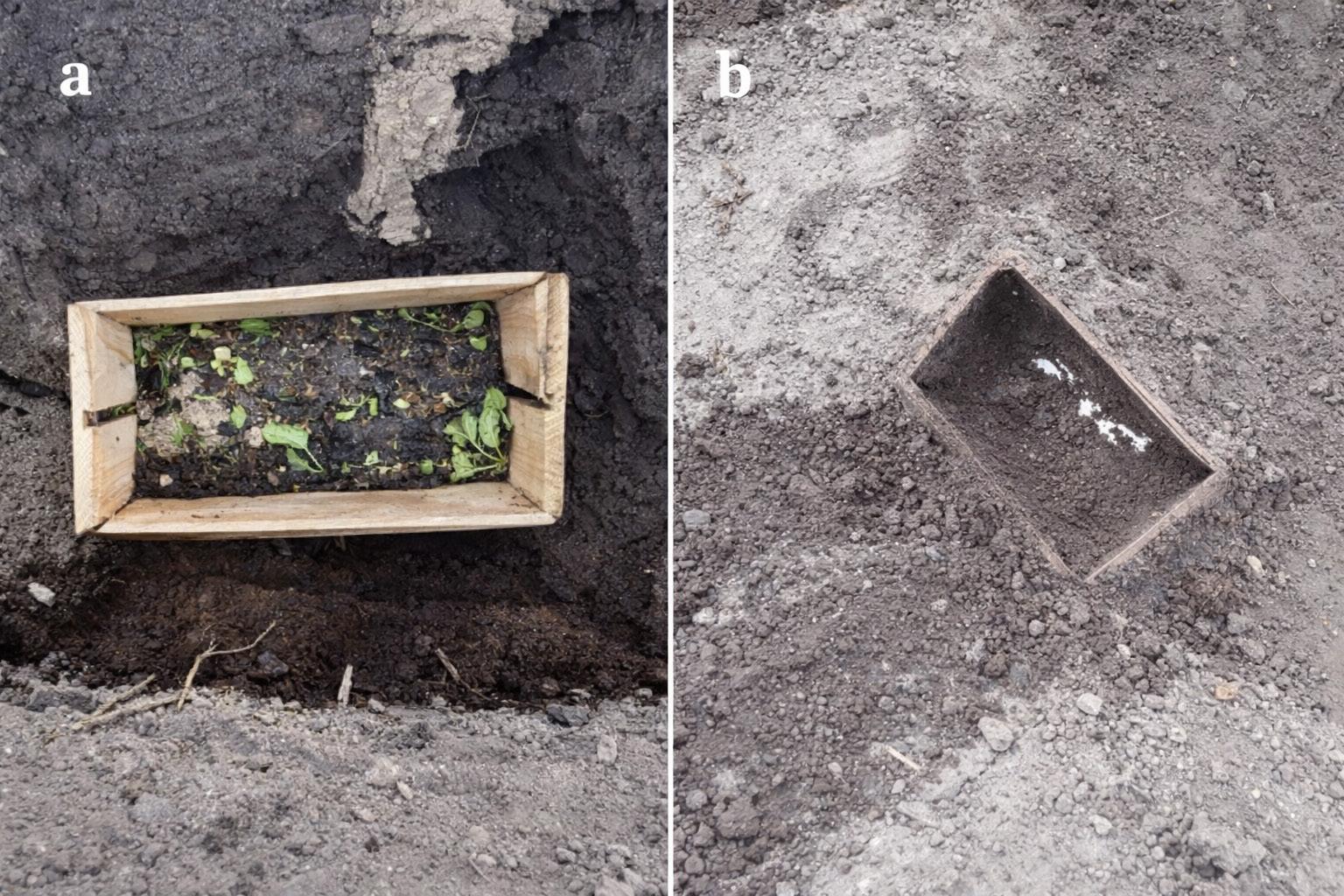
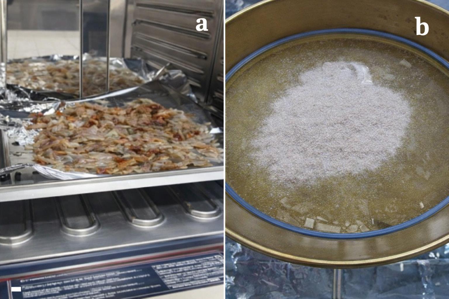
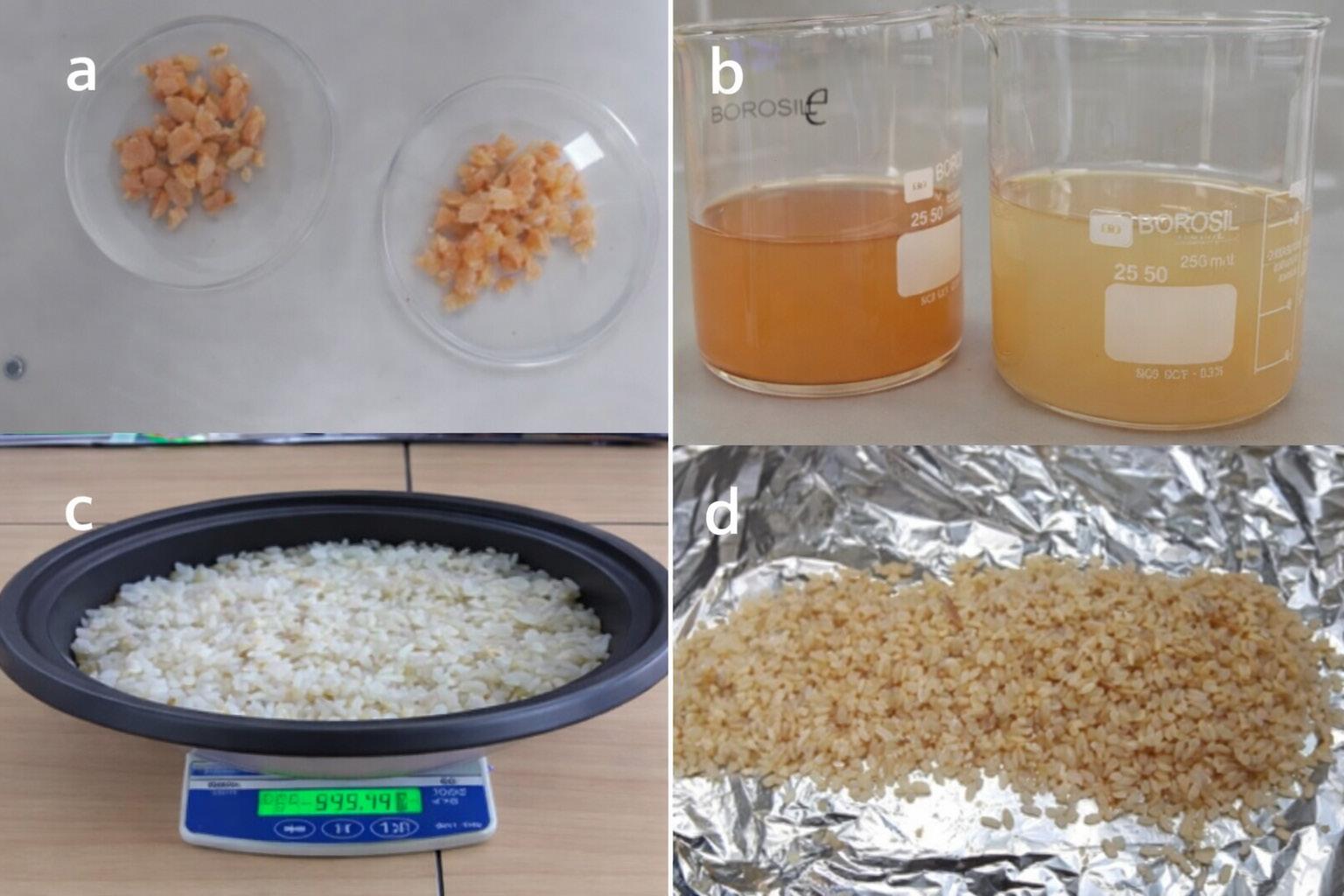
Although enzymatic deproteinization represents a less aggressive alternative compared to traditional alkaline methods, the chitin extraction process used in this study still entails significant use of hydrochloric acid for demineralization, acetic acid for decolorization, and high-temperature drying steps. These factors introduce important environmental burdens that moderate claims of sustainability.
The life cycle assessment conducted by[31] on chitin nanocrystal production included in PLA/PET packaging
materials reveals that even green extraction routes carry high impacts—particularly in terms of greenhouse gas emissions— when acid hydrolysis and drying energy are not optimized. The study shows that chitin nanoparticle production can contribute 3.21 kg CO2eq for PET and 4.26 kg CO2eq for ChNC/PLA composite, with potential reductions of 30–40% if HCl usage and energy consumption during drying are minimized.
Based on these insights, the process presented herein should be regarded as a partially improved alternative—not
Sustainable bioplastics based on shrimp chitin: mechanical characterization and biodegradability evaluation
yet fully sustainable. For future developments, implementing acid recovery, reducing reagent concentrations, optimizing reaction conditions, and adopting solar-assisted or lowtemperature drying technologies will be essential to improve the overall environmental footprint of chitinbased bioplastics.
In Table 2, the show the results that indicate that the first sample had a breaking point of 0.9 MPa, the second sample reached a breaking point of 0.6 MPa, and the third sample resulted in a breaking point of 1.0 MPa. As a result, the average elongation was determined to be 0.833 MPa, reflecting adequate resistance. Additionally, samples with lower chitin content were found to have inferior mechanical resistance, particularly sample 2.
In the research presented by [32-38] which similarly examined chitin, values of 0.6 and 0.9 MPa were reported, showing a strong similarity to the findings of the present study. However, the discrepancies may stem from differences in the methodologies or formulations utilized.
The analysis of the samples revealed notable differences in biopolymer flexibility. Samples 7 to 9 demonstrated superior compactness and flexibility, with sample 9 exhibiting increased hardness and thermal resistance after complete drying. In contrast, sample 3 had lower flexibility and reduced thermal resistance, while sample 6 was fragile to the touch. Additionally, samples with more than 6% chitin showed structural inconsistencies, whereas those with 5% chitin maintained a manually flexible structure. These findings emphasize the impact of composition and treatment on the biopolymer’s final mechanical properties.
Sample densities were determined through the application of the mass-volume relationship, with the results outlined in Table 3.
The average density measured was 2780 Kg/m3, which bears a resemblance to the findings reported in studies[39 40] this outcome suggests that the product exhibits thermoformable characteristics, attributed to the inclusion of polyethylene, a material commonly utilized in applications where weight is a crucial factor, alongside enhanced mechanical strength and stiffness.
The infrared spectroscopy analysis of the chitin, PET, and maleic anhydride mixture reveals notable interactions among the components, suggesting an enhancement in polymer compatibility (refer to Figure 4). The blue spectrum,
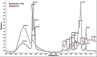
Amaya, J. B., & Sarango, P. D.
representing the biopolymer and PET blend, displays a peak at 3339.96 cm-1, which is associated with the -OH and -NH groups of biopolymer. This observation implies the potential formation of hydrogen bonds or reactions involving maleic anhydride. Furthermore, the peak at 1722.96 cm-1, indicative of the carbonyl group (-C=O) in PET, may reflect the influence of maleic anhydride, which exhibits bands in the 1780-1850 cm-1 range, suggesting the establishment of hydrogen bridge-type bonds with either chitin or PET, particularly as chitin is in a more hydrophilic state. Additional peaks at 1020.84 cm-1 and 1077.81 cm-1, characteristic of C-O-C stretching in esters, further imply interactions with maleic anhydride. A comparison with the red spectrum, which corresponds to pure biopolymer and shows a prominent band at 3302.84 cm-1, indicates that the introduction of the compatibilizer alters the polymer interactions[41]. Despite the inherent hydrophobic nature of PET and the hydrophilic characteristics of chitin, maleic anhydride serves as a coupling agent, facilitating reactions with the functional groups of chitin and potentially with the PET esters. This interaction enhances the adhesion between the phases and promotes a more uniform dispersion. The observation of shifts or broadening in significant bands would confirm the compatibilization of the mixture, thereby improving the integration of chitin within the PET matrix and augmenting its mechanical and structural properties for composite biopolymer applications.
The results of the TGA analysis are presented in Table 4, which indicates an initial temperature range of 50-100 °C. This range corresponds to the initial moisture loss associated with cellulose, starch, and chitin, attributable to their hydrophilic characteristics. Subsequently, a temperature range of 150-250 °C is noted, which relates to the volatilization of glycerol and acetic acid, as these plasticizers exhibit low thermal stability and decompose swiftly within this temperature interval. Finally, the analysis reveals a range of 250-400 °C, during which thermal degradation of natural polymers occurs, leading to the decomposition of both cellulose and chitin, resulting in carbonaceous residues. It is also observed that there is an initial mass loss of 5% due to the components of cellulose, starch, and chitin. Furthermore, at temperatures exceeding 400 °C, a significant mass loss of 85% is recorded, with the remaining mass comprising non-volatile carbonaceous residues. These residues include amorphous carbon resulting from the incomplete thermal decomposition of organic materials such as cellulose, starch, chitin, and glycerol, as well as mineral ash derived from inorganic compounds present in the raw materials or produced through the degradation of salts or impurities, including metal oxides[42,43].
The graph under (Figure 5) consideration illustrates three fundamental stages of the decomposition process. The first
50 5
100 12
150 23
Behavioral Description
Loss of adsorbed moisture (cellulose, starch and chitin).
Water desorption and initial volatilization of acetic acid.
Partial decomposition of starch and glycerol.
200 31 Continuous decomposition of glycerol and degradation of acetic acid.
250 43 Initiation of thermal decomposition of chitin.
300 55 Advanced starch and cellulose degradation.
350 72 Total degradation of chitin and cellulose.
400 85 Carbonaceous residues present (non-volatile compounds)
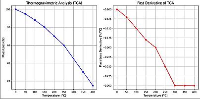
Sustainable bioplastics based on shrimp chitin: mechanical characterization and biodegradability evaluation
stage, occurring within the temperature range of 50-200°C, shows an initial mass loss of approximately 5-30%, likely due to the removal of adsorbed water and volatile materials. The second stage, which spans from 200-400°C, exhibits a considerable mass loss of around 30-85%, associated with the thermal degradation of cellulose and chitin. The final stage, beginning at 400°C, indicates a residual mass loss of approximately 85-100%, which is related to the degradation of PET. Furthermore, the first derivative of the thermogravimetric analysis (TGA) reveals distinct peaks that indicate the temperatures at which the rate of decomposition is maximized: the first peak (100-200°C) corresponds to the initial decomposition of cellulose and the release of water, the second peak (300-400°C) relates to the primary decomposition of cellulose and chitin, and the third peak (400°C and above) is associated with the degradation of PET[30,44-46]. .
The composting tests conducted provided an assessment of the degradability of the bioplastic produced under controlled conditions, as detailed in Table 5. The results indicate that the degradation of the samples is predominantly influenced by the duration of exposure, with temperature exerting a moderate effect, while relative humidity appears to have a minimal role in the evaluated conditions. In the initial assessment, no degradation was recorded after one day, even at a temperature of 20.2 °C and a humidity level of 30%. In the
subsequent evaluation, an increase in temperature to 24.6 °C and an exposure period of 30 days resulted in a degradation rate of 25%, despite a decrease in relative humidity to 20%. Ultimately, the third evaluation, which extended over 120 days at a temperature of 23.7 °C and a consistent humidity of 20%, resulted in complete degradation (100%). These findings suggest that the duration of exposure is the most critical factor influencing the degradation processes observed.
In Table 6 presents the findings indicating that the bioplastic underwent nearly complete degradation over a period of 120 days. This is further evidenced by a notable degradation rate of 25% observed at the 30-day mark in the second evaluation, which may also be attributed to the carbon dioxide produced during the degradation process. The study referenced in[47,48] supports this observation, noting that a similar dosage resulted in complete degradation within 100 days, thereby reinforcing the correlation between temperature and the rate of decomposition. Additionally, a decrease in humidity was noted, likely influenced by temperate climatic conditions. In the third evaluation, conducted at a temperature of 23.7°C and 20% humidity (as illustrated in Figure 6b), nearly total degradation was again achieved within 120 days. This outcome suggests that, despite the lower temperature compared to the second evaluation, the prolonged duration facilitated maximum degradation, particularly under stable temperature and humidity conditions. The graphical representation in Figure 6 further illustrates these findings.
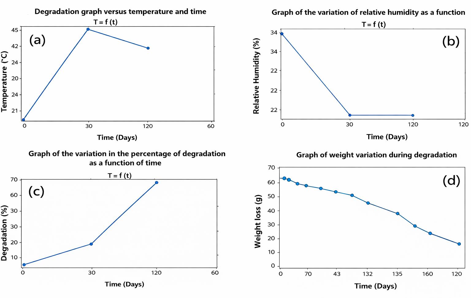
Table 6. Results of weight loss in the degradability analysis.
The results depicted in Table 6 and Figure 6d indicate that the weight loss of the bioplastic remained relatively stable during the initial days, followed by an acceleration in degradation over time Figure 6c, culminating in almost total weight loss by the end of the 120-day period Figure 6a It is important to note that the biodegradability results presented in this study are based on visual disintegration and mass loss measurements under composting conditions. While these findings indicate structural breakdown of the material, they do not confirm complete molecular degradation. Future work should include advanced analyses such as gas evolution (CO2 monitoring), spectroscopic techniques (e.g., FTIR, NMR), and microbial assays to fully characterize the biodegradation pathways and assess environmental safety of the degradation products
The current research illustrates the potential for developing a thermoformable bioplastic from chitin sourced from shrimp exoskeletons as the principal raw material. The results underscore that this bioplastic exhibits mechanical properties that are conducive to industrial applications, with an average tensile strength recorded at 0,833 MPa and a density of 2780 Kg/m3. Additionally, the bioplastic formulation containing 5% chitin was found to possess optimal characteristics in terms of stiffness and structural flexibility, making it the preferred candidate for prospective applications. In terms of biodegradability, the bioplastic achieved complete degradation within a span of 120 days under regulated composting conditions, thereby supporting its compatibility with circular economy frameworks and environmental sustainability initiatives. Thermogravimetric analyses indicated that the thermal degradation process of the material is influenced by the polymeric composition and the thermal stability of the constituent components, particularly chitin, starch, and glycerol.
5. Author’s Contribution
● Conceptualization – Jorge Braulio Amaya.
● Data curation – Jorge Braulio Amaya.
● Formal analysis – Jorge Braulio Amaya.
● Funding acquisition – NA.
● Investigation – Jorge Braulio Amaya; Paola Duque Sarango.
● Methodology – Jorge Braulio Amaya.
● Project administration – Jorge Braulio Amaya.
● Resources – Jorge Braulio Amaya.
● Software – NA.
● Supervision – Jorge Braulio Amaya.
● Validation – Verification, Paola Duque Sarango.
● Visualization – Jorge Braulio Amaya; Paola Duque Sarango.
● Writing – original draft – Jorge Braulio Amaya; Paola Duque Sarango.
● Writing – review & editing – Jorge Braulio Amaya; Paola Duque Sarango.
The authors are thankful for the support offered by the Salesian Polytechnic University of Cuenca, Ecuador, and would like to recognize the contributions of the biodiversity research and evaluation group, GIVABI, in addition to the life sciences laboratories at the University.
7. References
1 Rujnić-Sokele, M., & Pilipović, A. (2017). Challenges and opportunities of biodegradable plastics: a mini review. Waste Management & Research, 35(2), 132-140 https://doi. org/10.1177/0734242X16683272. PMid:28064843.
2 Emadian, S. M., Onay, T. T., & Demirel, B. (2017). Biodegradation of bioplastics in natural environments. Waste Management, 59, 526-536 https://doi.org/10.1016/j.wasman.2016.10.006 PMid:27742230.
3 Thompson, R. C., Olsen, Y., Mitchell, R. P., Davis, A., Rowland, S. J., John, A. W. G., Mcgonigle, D., & Russell, A. E. (2004). Lost at sea: where is all the plastic? Science, 304(5672), 838 https://doi.org/10.1126/science.1094559 PMid:15131299.
4 Barnes, D. K. A., Galgani, F., Thompson, R. C., & Barlaz, M. (2009). Accumulation and fragmentation of plastic debris in global environments. Philosophical Transactions of the Royal Society of London. Series B, Biological Sciences, 364(1526), 1985-1998 https://doi.org/10.1098/rstb.2008.0205 PMid:19528051.
5. Geyer, R., Jambeck, J. R., & Law, K. L. (2017). Production, use, and fate of all plastics ever made. Science Advances, 3(7), e1700782 https://doi.org/10.1126/sciadv.1700782 PMid:28776036.
6 Jambeck, J. R., Geyer, R., Wilcox, C., Siegler, T. R., Perryman, M., Andrady, A., Narayan, R., & Law, K. L. (2015). Plastic waste inputs from land into the ocean. Science, 347(6223), 768-771 https://doi.org/10.1126/science.1260352 PMid:25678662.
Sustainable bioplastics based on shrimp chitin: mechanical characterization and biodegradability evaluation
7 Muñoz-Tebar, N., Pérez-Álvarez, J. A., Fernández-López, J., & Viuda-Martos, M. (2023). Chitosan edible films and coatings with added bioactive compounds: antibacterial and antioxidant properties and their application to food products. Polymers, 15(2), 396 https://doi.org/10.3390/polym15020396 PMid:36679276.
8 Ifuku, S. (2014). Chitin and chitosan nanofibers: preparation and chemical modifications. Molecules, 19(11), 18367-18380 https://doi.org/10.3390/molecules191118367 PMid:25393598.
9 Younes, I., & Rinaudo, M. (2015). Chitin and chitosan preparation from marine sources: Structure, properties, and applications. Marine Drugs, 13(3), 1133-1174 https://doi. org/10.3390/md13031133 PMid:25738328.
10. Zhou, Y., He, Y., Lin, X., Feng, Y., & Liu, M. (2022). Sustainable, high-performance, and biodegradable plastics made from chitin. ACS Applied Materials & Interfaces, 14(41), 46980-46993 https://doi.org/10.1021/acsami.2c12764 PMid:36201725.
11 Ravi Kumar, M. N. V. (2000). A review of chitin and chitosan applications. Reactive & Functional Polymers, 46(1), 1-27 https://doi.org/10.1016/S1381-5148(00)00038-9
12 Bakshi, P. S., Selvakumar, D., Kadirvelu, K., & Kumar, N. S. (2020). Chitosan as an environment-friendly biomaterial: A review on recent modifications and applications. International Journal of Biological Macromolecules, 150, 1072-1083. https:// doi.org/10.1016/j.ijbiomac.2019.10.113 PMid:31739057.
13 Percot, A., Viton, C., & Domard, A. (2003). Optimization of chitin extraction from shrimp shells. Biomacromolecules, 4(1), 12-18 https://doi.org/10.1021/bm025602k PMid:12523840.
14 Torres, O. A., Márquez, A. M., Bárcena-Ochoa, E. M., Flores, R., Gómez, R. S. G., & Bazúa, M. D. C. D. D. (2018). Comparación de diferentes agentes plastificantes adicionados en esponjas de quitina obtenidas de cefalotórax de camarón. Química Central, 3(1), 11-18. https://doi.org/10.29166/quimica.v3i1.1200.
15 Arévalo, E. Y. B., & Sablón-Cossió, N. (2022). Evaluación de la economía circular en una empacadora de camarón en Ecuador. AquaTechnica, 4(3), 134-142 https://doi.org/10.33936/ at.v4i3.5275
16 Castillo-Ochoa, B. del C., & Velásquez-López, P. C. (2021). Manejo estacional de los sistemas de producción de camarón en el Ecuador. Sociedad & Tecnología, 4(3), 447-461 https:// doi.org/10.51247/st.v4i3.151.
17 Rossi, N., Grosso, C., & Delerue-Matos, C. (2024). Shrimp waste upcycling: unveiling the potential of polysaccharides, proteins, carotenoids, and fatty acids with emphasis on extraction techniques and bioactive properties. Marine Drugs, 22(4), 153 https://doi.org/10.3390/md22040153 PMid:38667770.
18 Shamshina, J. L., Berton, P., & Rogers, R. D. (2019). Chitin as a resource for eco-friendly bioplastics. In S. Zhang (Ed.), Encyclopedia of ionic liquids (pp. 203-210). Singapore: Springer https://doi.org/10.1007/978-981-10-6739-6_43-1.
19 Suriyatem, R., Auras, R. A., & Rachtanapun, P. (2018). Improvement of mechanical properties and thermal stability of biodegradable rice starch–based films blended with carboxymethyl chitosan. Industrial Crops and Products, 122, 37-48 https://doi.org/10.1016/j.indcrop.2018.05.047
20 Negrete-Bolagay, D., & Guerrero, V. H. (2024). Opportunities and challenges in the application of bioplastics: perspectives from formulation, processing, and performance. Polymers, 16 (18), 2561. https://doi.org/10.3390/polym16182561. PMid:39339026.
21 Piekarska, K., Sikora, M., Owczarek, M., Jóźwik-Pruska, J., & Wiśniewska-Wrona, M. (2023). Chitin and chitosan as polymers of the future: obtaining, modification, life cycle assessment and main directions of application. Polymers, 15(4), 793 https:// doi.org/10.3390/polym15040793 PMid:36850077.
22 Priyadarshi , R., & Rhim, J.-W. (2020). Chitosan-based biodegradable functional films for food packaging applications. Innovative Food Science & Emerging Technologies, 62, 102346. https://doi.org/10.1016/j.ifset.2020.102346
23 Oberlintner, A., Bajić, M., Kalčíková, G., Likozar, B., & Novak, U. (2021). Biodegradability study of active chitosan biopolymer films enriched with Quercus polyphenol extract in different soil types. Environmental Technology & Innovation, 21, 101318 https://doi.org/10.1016/j.eti.2020.101318
24 Minor, M., Vingerhoeds, M. H., Zoet, F. D., Wijk, R., & Van Aken, G. A. (2009). Preparation and sensory perception of fatfree foams – effect of matrix properties and level of aeration. International Journal of Food Science & Technology, 44(4), 735-747 https://doi.org/10.1111/j.1365-2621.2008.01887.x
25 Tan, S. X., Ong, H. C., Andriyana, A., Lim, S., Pang, Y. L., Kusumo, F., & Ngoh, G. C. (2022). Characterization and parametric study on mechanical properties enhancement in biodegradable chitosan-reinforced starch-based bioplastic film. Polymers, 14(2), 278 https://doi.org/10.3390/polym14020278 PMid:35054685.
26. Bojórquez, L. A. C. (2023). Desechos de camarón: un coctel de oportunidades para la industria. In Seminario del Programa de Especialidad en Nutrición y Alimentos Funcionales del CEPROBI-IPN, Yautepec, México: Instituto Politécnico Nacional; Centro de Desarrollo de Productos Bióticos. Retrieved in 2025, May 1, from https://www.ceprobi.ipn.mx/assets/files/ ceprobi/docs/eventos/memorias-enaf-2023.pdf
27 Quiñones-Cerna, C., Rodríguez-Soto, J. C., Hurtado-Butrón, F., Centeno-Calderón, L., Mejia-Ruedell, R., López-Quiroz, E., Gálvez-Rivera, J., & Ugarte-López, W. (2024). Efficient chitin extraction from shrimp exoskeletons through single-step fermentation by Pseudomonas aeruginosa QF50 and Serratia sp. QCS23. Processes, 12(6), 1184 https://doi.org/10.3390/ pr12061184
28 Dong, Q., Qiu, W., Feng, Y., Jin, Y., Deng, S., Tao, N., & Jin, Y. (2023). Proteases and microwave treatment on the quality of chitin and chitosan produced from white shrimp (Penaeus vannamei). eFood, 4(2), e73 https://doi.org/10.1002/efd2.73
29 Pimtong, V., Ounaeb, S., Thitiprasert, S., Tolieng, V., Sooksai, S., Boonsombat, R., Tanasupawat, S., Assabumrungrat, S., & Thongchul, N. (2017). Enhanced effectiveness of Rhizopus oryzae by immobilization in a static bed fermentor for l-lactic acid production. Process Biochemistry, 52, 44-52 https://doi. org/10.1016/j.procbio.2016.09.020
30 Nurazzi, N. M., Asyraf, M. R. M., Rayung, M., Norrrahim, M. N. F., Shazleen, S. S., Rani, M. S. A., Shafi, A. R., Aisyah, H. A., Radzi, M. H. M., Sabaruddin, F. A., Ilyas, R. A., Zainudin, E. S., & Abdan, K. (2021). Thermogravimetric analysis properties of cellulosic natural fiber polymer composites: A review on influence of chemical treatments. Polymers, 13(16), 2710. https://doi.org/10.3390/polym13162710 PMid:34451248.
31 Yanat, M., Voortman, E., Buijsse, C., & Schroën, K. (2025). Life cycle assessment (LCA) of chitin nanocrystal reinforced polylactic acid (ChNC/PLA) and polyethylene terephthalate (PET) packaging material. Carbohydrate Polymers, 348(Pt B), 122927 https://doi.org/10.1016/j.carbpol.2024.122927 PMid:39567145.
32 Piri Santana, J. (2017). Synthesis and physicochemical characterization of biopolymeric nanoplatforms of chitosan, cisplatin and thiolated chitosan by ionic gelation and their potential application as transporters of a drug (Master’s dissertation). Autonomous University of the State of Morelos, Cuernavaca, Mexico
33. Dewi, A. P., Mardhiyana, A., Manfaati, R., & Leoanggraini, U. (2023). The effect of additional chitosan and cellulose on the performance of bioplastic from Manihot Glaziovii starch. Fluida, 16(1), 36-42 https://doi.org/10.35313/fluida.v16i1.4394
J. B., & Sarango, P. D.
34 Zhang, L., Wang, Z., Xiao, Y., Liu, P., Wang, S., Zhao, Y., Shen, M., & Shi, X. (2018). Electrospun PEGylated PLGA nanofibers for drug encapsulation and release. Materials Science and Engineering C, 91, 255-262 https://doi.org/10.1016/j. msec.2018.05.045 PMid:30033253.
35 Sun, X., Li, J., Shao, K., Su, C., Bi, S., Mu, Y., Zhang, K., Cao, Z., Wang, X., Chen, X., & Feng, C. (2021). A composite sponge based on alkylated chitosan and diatom-biosilica for rapid hemostasis. International Journal of Biological Macromolecules, 182, 2097-2107 https://doi.org/10.1016/j. ijbiomac.2021.05.123 PMid:34081956.
36. Arias-Nava, E. H., Valles-Rosales, D. J., & Sullivan, B. P. (2023). Biopolymer non-parametric analysis: A degradation study under accelerated destructive tests. Polymers, 15(3), 620 https://doi.org/10.3390/polym15030620 PMid:36771920.
37. Howard, S., & Montogomery, T. (2024). Long-term coreflood testing with biopolymers—A laboratory investigation showing how return permeability improves from 0 to 100 percent by getting a critical parameter right. In SPE International Conference and Exhibition on Formation Damage Control, Lafayette, Louisiana, USA: SPE International. https://doi.org/10.2118/217909-MS.
38 Sharma, S. J., Gupta, R., & Gupta, M. (2024). Advanced testing and biocompatibility strategies for sustainable biomaterials. Biotechnology for Sustainable Materials, 1(1), 18 https://doi. org/10.1186/s44316-024-00018-7
39 Rhim, J.-W., Park, H.-M., & Ha, C.-S. (2013). Bio-nanocomposites for food packaging applications. Progress in Polymer Science, 38(10–11), 1629-1652 https://doi.org/10.1016/j. progpolymsci.2013.05.008
40 Walujodjati, E., Johari, G. J., & Farida, I. (2019). Confinement influence in cracking areas single reinforced concrete. Journal of Physics: Conference Series, 1402(2), 022013 https://doi. org/10.1088/1742-6596/1402/2/022013
41. Uzun, I., & Celik, O. (2015). Physicochemical characterization and the comparison of chitin and chitin modified with maleic anhydride. Oriental Journal of Chemistry, 31(2), 619-627 https://doi.org/10.13005/ojc/310202
42 Chandra , D. K. , Kumar, A. , & Mahapatra , C. ( 2024 ). Fabricating chitosan reinforced biodegradable bioplastics from plant extract with nature inspired topology. Waste and Biomass Valorization , 15 (4), 2499-2512 https://doi. org/10.1007/s12649-023-02293-3.
43 Schnabl, K. B., Mandemaker, L. D. B., Ganjkhanlou, Y., Vollmer, I., & Weckhuysen, B. M. (2024). Green additives in chitosan-based bioplastic films: long-term stability assessment and aging effects. ChemSusChem, 17(13), e202301426 https:// doi.org/10.1002/cssc.202301426 PMid:38373235.
44 Köll, P., & Metzger, J. (1978). Thermal degradation of cellulose and chitin in supercritical acetone. Angewandte Chemie International Edition in English, 17(10), 754-755. https://doi. org/10.1002/anie.197807541
45 Cichosz, S., & Masek, A. (2020). Thermal behavior of green cellulose-filled thermoplastic elastomer polymer blends. Molecules, 25(6), 1279 https://doi.org/10.3390/molecules25061279 PMid:32178229.
46 Stawski, D., Rabiej, S., Herczyńska, L., & Draczyński, Z. (2008). Thermogravimetric analysis of chitins of different origin. Journal of Thermal Analysis and Calorimetry, 93(2), 489-494 https://doi.org/10.1007/s10973-007-8691-6
47 Cacique, P. P., Rios, M. N. M., Barbosa, I. O., & Wentz, A. P. (2017). Bioplastics production from starch and chitosan blends. Revista Eletrônica Perspectivas da Ciência e Tecnologia , 9 , 46 - 53 . https://doi.org/10.22407/19845693.2017.v9.p.46-53
48 Wrońska, N., Katir, N., Nowak-Lange, M., El Kadib, A., & Lisowska, K. (2023). Biodegradable chitosan-based films as an alternative to plastic packaging. Foods, 12(18), 3519 https://doi.org/10.3390/foods12183519 PMid:37761228.
Received: May 01, 2025
Revised: Aug. 08, 2025
Accepted: Aug. 28, 2025
Editor-in-Chief: Sebastião V. Canevarolo
Sundaramahalingam Subramaniam1* and Manikandan Bairavan Veerayan1
1Department of Electrical and Electronics Engineering, Mepco Schlenk Engineering College, Sivakasi, Tamil Nadu, India
*sundar.eee@mepcoeng.ac.in
Obstract
Polypropylene (PP) is a promising insulation material for high-voltage direct current (HVDC) cables due to its electrical, thermal, and chemical stability. However, limitations such as high thermal expansion coefficient, low thermal conductivity, and poor flame retardancy restrict its direct application. This study investigates incorporating nano-scale oxide (MgO) and nitride (AlN) fillers into PP via solution blending to enhance dielectric performance. Nanocomposites with varying filler concentrations were prepared, and their AC breakdown strength and DC conductivity were evaluated. Results show that PP filled with 3 wt% AlN and 3 wt% MgO exhibited improvements in AC breakdown strength 15.4% and 13.82%, respectively compared to pure PP. DC conductivity analysis indicated reduced leakage current for nanocomposites at optimal filler concentrations, supporting their suitability for HVDC insulation. The incorporation of oxide and nitride nano-fillers into PP matrix enhanced electrical insulation characteristics, confirming these nanocomposites’ potential for advanced HVDC cable applications
Keywords: aluminum nitride, breakdown strength, magneisum oxide, polypropylene.
Data Ovailability: All data supporting the findings of this study are available from the corresponding author upon request.
How to cite: Subramaniam, S., & Veerayan, M. B. (2026). Comparative analysis of nitride and oxide based nano fillers for polypropylene insulation. Polímeros: Ciência e Tecnologia, 36(1), e20260002. https://doi.org/10.1590/01041428.20250006
The global demand for electricity continues to grow rapidly, with annual electricity production expected to exceed 38,000 terawatt-hours by 2040, rising from 24,000 terawatthours in 2016[1]. In response to environmental concerns and the push for sustainability, renewable energy sources are projected to account for 51% of total electricity generation by 2040, a substantial increase from 22% in 2016. While this transition is essential for environmental preservation, it also poses new challenges for energy infrastructure, particularly in maintaining grid stability, efficiency, and long-distance power transmission.
To accommodate this shift, robust and sustainable power transmission systems must be developed. High-Voltage Direct Current (HVDC) transmission has emerged as a promising solution, particularly for long-distance and high-capacity energy transfer. Compared to High-Voltage Alternating Current (HVAC) systems, HVDC offers reduced transmission losses, lower line tower construction requirements, and faster repair times, making it highly suitable for overhead, underground, and submarine applications[2-4]. As global investments in submarine power cable projects increase, optimizing cable insulation materials becomes critical to improve performance and reduce energy losses.
Traditional HVDC cable insulation materials, particularly cross-linked polyethylene (XLPE), have limitations such as poor recyclability, high energy consumption during processing, and environmental concerns. These issues highlight the urgent need to explore non-cross-linked, recyclable, and environmentally friendly alternatives. Polypropylene (PP) has emerged as a strong candidate due to its favorable electrical, thermal, and chemical properties. PP maintains excellent electrical insulation regardless of humidity or frequency, exhibits high heat resistance (up to 373 K), and resists chemical degradation.
However, pure PP suffers from inherent drawbacks such as low flame retardancy, high thermal expansion, and poor thermal conductivity[5]. To address these limitations, researchers have focused on enhancing PP properties through nano-filler reinforcement, creating polypropylene-based nanocomposites.
Recent studies have explored the use of TiO2, ZnO, MgO, and AlN nano-fillers to improve PP’s dielectric and thermal properties. For example, Li et al.[6] demonstrated that adding 3 wt% TiO2 to PP significantly improves AC breakdown strength (up to 5.5 kV), while ZnO-based composites also showed higher dielectric strength under high-frequency AC voltage[7]. Similarly, Azrin et al.[8] reported that PP-MgO-
Subramaniam, S., & Veerayan, M. B.
C8 nanocomposites exhibited up to 27.4% improvement in dielectric strength under DC stress compared to pure PP. Mazumde et al.[9] studied thermal conductivity improvements in PP nanocomposites by adding boron nitride (BN). The incorporation of plate-like BN particles improved heat dissipation while maintaining electrical insulation. This is critical for HVDC applications where temperature rise due to Joule heating can deteriorate insulation materials.
Similarly, Ruan et al.[10] showed that silica-coated AlN nano fillers in PP provided uniform dispersion, improved thermal conductivity, and reduced interfacial polarization, enhancing both dielectric and thermal properties. Wu et al. [11] established that the interface between polymer matrix and nano-fillers plays a vital role in trap formation, which helps suppress space charge. Surface modification techniques, such as silane treatment or organic functionalization, have been proven effective in reducing charge mobility and improving insulation longevity. Du et al.[12] also demonstrated that using surface-treated MgO nano fillers in PP not only increased trap density but also stabilized the dielectric constant, which is crucial for long-term operation under DC stress.
These studies collectively demonstrate that nano-fillerenhanced polypropylene materials offer a promising path toward high-performance, sustainable HVDC cable insulation. However, more comprehensive analysis is required to determine the optimal combinations and concentrations of nano-fillers for achieving superior electrical performance and long-term reliability. This research investigates the electrical characteristics of PP-based nanocomposites with various nano-filler loadings to identify suitable insulation materials for future HVDC cable systems.
The material used in this study is isotactic polypropylene (iPP) (Sigma Aldrich), with temperature of 12g/10min, its isotopicity of 95%, and its melting temperature of 170°C. Two types of nano fillers were used. Aluminum nitride (AlN,30 - 50nm) and magnesium oxide (MgO, 5 – 100nm) were obtained from Vedayukt India and Techinstro[13] Figure 1 shows the flow chart for the preparation of the samples.
To investigate the effect of different nano-filler loadings on the dielectric performance of polypropylene, six nanocomposite samples were prepared with varying concentrations of MgO and AlN: 2%, 3%, and 5% by weight relative to the PP matrix. The general preparation procedure involved dissolving PP in xylene, dispersing nano-fillers using toluene (for AlN), and employing magnetic stirring under controlled temperature and speed conditions.
To investigate the effects of nano-filler loading on the dielectric properties of polypropylene (PP), six nanocomposite samples were prepared using varying concentrations of magnesium oxide (MgO) and aluminum nitride (AlN). In all samples, 3 g of isotactic polypropylene was placed in a beaker and heated for 3 minutes using a magnetic stirrer to initiate softening. Following this, 10 mL of xylene was added as a solvent, and the mixture was stirred for 30 minutes to ensure complete dissolution of PP. For MgO-based samples, nano-filler concentrations of 2 wt%, 3 wt%, and 5 wt% were incorporated directly into the PP-xylene solution corresponding to 0.06 g, 0.09 g, and 0.15 g of MgO, respectively. Each mixture was subjected to continuous magnetic stirring at 350 RPM and 75°C for 1 hour and 15 minutes to ensure uniform dispersion of the nanoparticles. After processing, the solutions were cooled and left to solidify at room temperature for 24 hours.
For AlN-based samples, the same base PP-xylene mixture was prepared, after which AlN was separately dispersed in 2.5 mL of toluene and preheated at 100°C for 45 minutes under magnetic stirring to enhance dispersion. The prepared AlN dispersions, at concentrations of 2 wt% (0.06 g), 3 wt% (0.09 g), and 5 wt% (0.15 g), were then introduced into the PP solution. These combined mixtures were further stirred under identical conditions (350 RPM, 75°C, 1 hour 15 minutes), followed by 24-hour curing at room temperature. As shown in Figure 2, All six samples PP/2% MgO, PP/3% MgO, PP/5% MgO, PP/2% AlN, PP/3% AlN, and PP/5% AlN were then subjected to further physical and electrical characterization. Xylene was used for MgO dispersion due to its good solvency for PP and compatibility with metal oxides, whereas toluene was selected for AlN owing to its
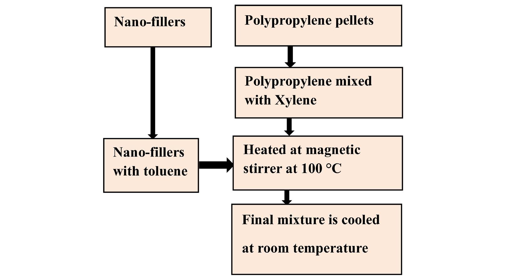
Comparative analysis of nitride and oxide based nano fillers for polypropylene insulation
favorable polarity for dispersing ceramic nitrides. These choices promote effective dispersion and matrix interaction.
The different contents of nano fillers and PP are presented in Table 1.
Fourier Transform Infrared Spectroscopy (FTIR) is observed for different prepared samples to find the presence of functional groups and to confirm molecular interactions between the polymer matrix and nano-fillers. In Figures 3 and 4, FTIR spectra for PP+3% AlN and PP+3% MgO nanocomposites. As expected, both spectra show prominent absorption peaks in the 2850–3000 cm−1 range, corresponding to C–H stretching vibrations of the methyl and methylene groups inherent in the polypropylene backbone. The persistence of these characteristic peaks confirms that
the chemical structure of the base PP matrix remains intact after the incorporation of nano-fillers.
While the nano-fillers themselves (AlN and MgO) are inorganic and do not exhibit strong IR-active modes in this region, their presence influences the polymer chain interactions. Notably, in both nanocomposite samples, subtle shifts in peak positions and variations in intensity are observed when compared to pure PP. These spectral changes although not indicative of covalent bonding suggest physical interactions and interfacial compatibility between the nano-fillers and the PP matrix. Such interfacial interactions are crucial for efficient stress transfer, dielectric enhancement, and suppression of charge accumulation in HVDC cable applications.
Furthermore, the selection of 3 wt% filler loading is supported not only by FTIR observations but also by our broader study results, including dielectric breakdown strength, thermal stability, and dispersion uniformity.
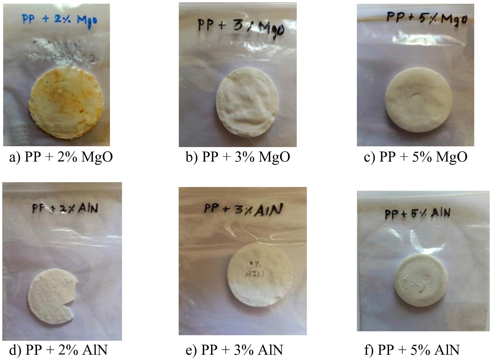
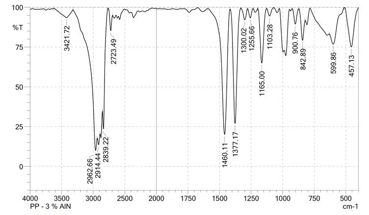
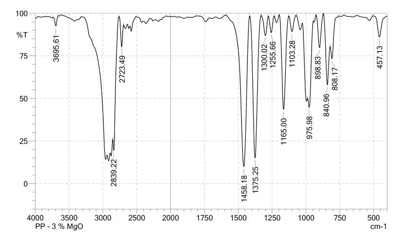
At this concentration, the nanocomposites exhibited an optimal balance between enhanced dielectric properties and processability. Higher filler loadings (5 wt%) tended to introduce agglomeration, which negatively impacts insulation performance and material homogeneity. On the other hand, lower concentrations (2 wt%) showed minimal improvements in electrical characteristics.
Thus, the FTIR analysis, in conjunction with other material characterization results, confirms that 3 wt% AlN and MgO filler concentrations are effective for achieving the required thermal and electrical performance needed in HVDC cable insulation applications. The findings are consistent with previous literature reporting[14-16] optimal nano-filler ranges for polymer-based dielectric composites.
Scanning Electron Microscopy (SEM) was conducted to examine the morphology and dispersion characteristics of nano-fillers within the polypropylene (PP) matrix. The SEM images provide crucial insights into the microstructural uniformity, interfacial adhesion, and agglomeration behavior of MgO and AlN nanoparticles at various concentrations. Figures 5 and 6 show the SEM micrographs of PP+3% MgO
and PP+5% MgO composites, respectively, recorded at a magnification of ×150 with an accelerating voltage of 10.0 kV and a working distance of 11.0 mm. From these images, it is evident that the MgO nanoparticles are relatively well dispersed throughout the PP matrix, with minimal visible agglomeration. The homogenous distribution enhances the dielectric uniformity and contributes positively to the insulation performance of the nanocomposite.
Similarly, Figure 7 presents the SEM image of PP+5% AlN, captured at 20 µm scale, using a 20.0 kV accelerating voltage and an 11.0 mm working distance. Figure 8 shows a higher magnification view at the 10 µm scale for the same PP+5% AlN sample under identical voltage and distance settings. To quantify nano-filler dispersion, SEM images were analyzed using ImageJ software. Results confirm a uniform dispersion pattern at 3 wt% filler loading, with minor agglomeration observed at 5 wt%.In both images, the AlN nano-fillers are seen to be uniformly embedded in the PP matrix, indicating successful dispersion and matrix compatibility.
Importantly, surface modification of the nano-fillers using γ-methacryloxypropyltrimethoxysilane (MPS) played a significant role in achieving this uniform dispersion. The silane treatment enhances interfacial adhesion and prevents particle agglomeration, which is critical for maintaining
Comparative analysis of nitride and oxide based nano fillers for polypropylene insulation
the electrical integrity and mechanical strength of the nanocomposite. The observed morphological uniformity in both MgO and AlN-filled composites confirms that particle–matrix compatibility is high, thereby minimizing localized field distortions and enhancing the dielectric performance—making these materials suitable for HVDC cable insulation applications.
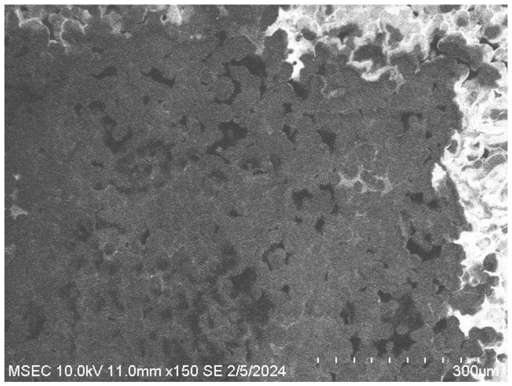
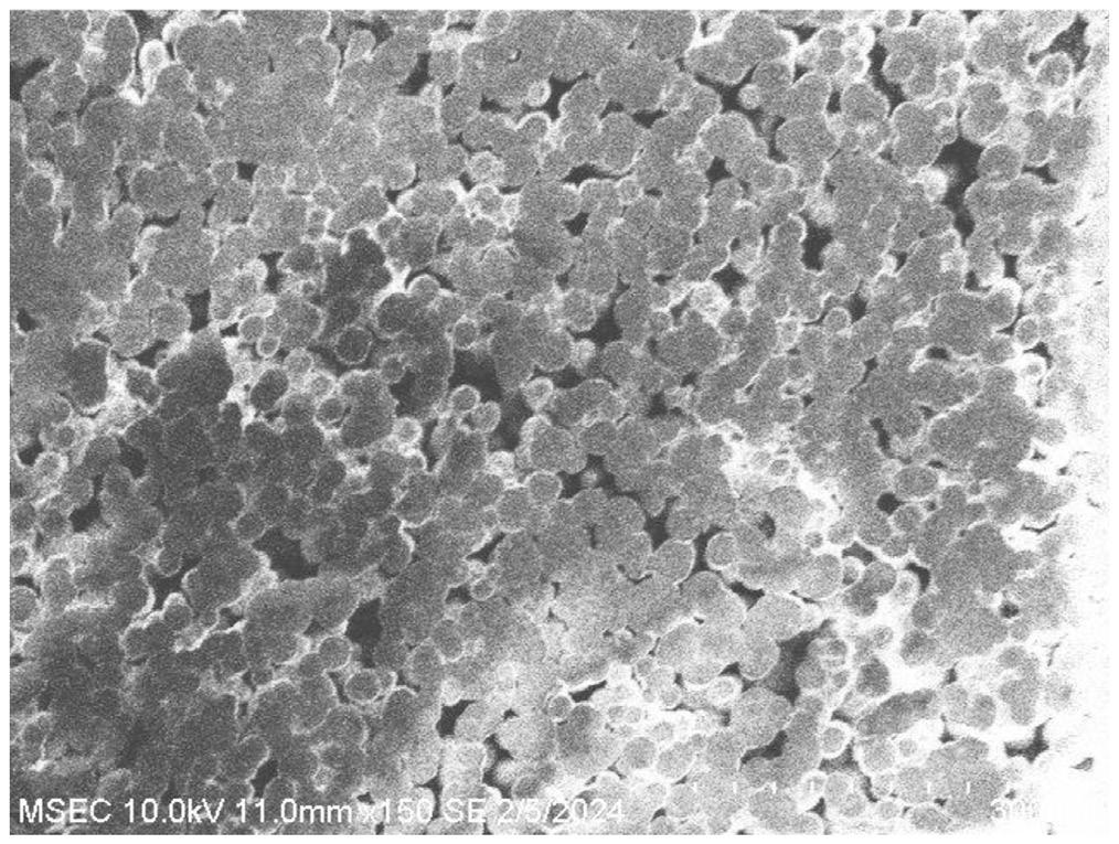
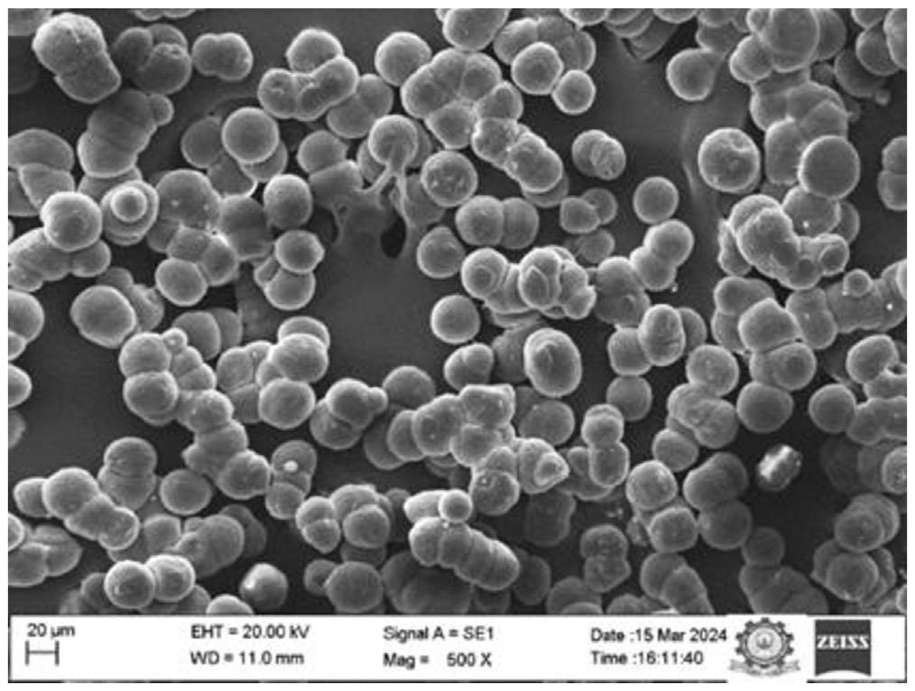
As part of this study, X-ray Diffraction (XRD) analysis was conducted for all prepared nanocomposite samples to evaluate their crystalline structure, phase purity, and the effect of nano-filler incorporation on the crystallinity of the polypropylene (PP) matrix. As shown in Figures 9 and 10 The results revealed that the addition of nano-fillers significantly influenced the crystalline behavior of PP. Notably, the samples containing 3 wt% MgO and 3 wt% AlN exhibited enhanced peak intensities associated with the α-phase of isotactic polypropylene, suggesting an improvement in overall crystallinity and ordered structure. This enhancement can be attributed to the nucleating effect of the well-dispersed nano-fillers, which promote the formation of smaller, more uniformly distributed crystallites.
The 3% filler concentration was found to be optimal, as higher concentrations (e.g., 5%) led to slight peak broadening and reduced intensity, indicating potential agglomeration and distortion of the polymer matrix, which may compromise dielectric performance. Conversely, lower concentrations (e.g., 2%) showed negligible changes compared to pure PP, suggesting insufficient interaction between the filler and the matrix.
The PP+3% AlN composite exhibited broader and less intense diffraction peaks compared to the PP+3% MgO composite. This suggests smaller AlN crystallite sizes or a higher degree of interfacial interaction with the polymer matrix, which may suppress sharp crystallinity. In contrast,
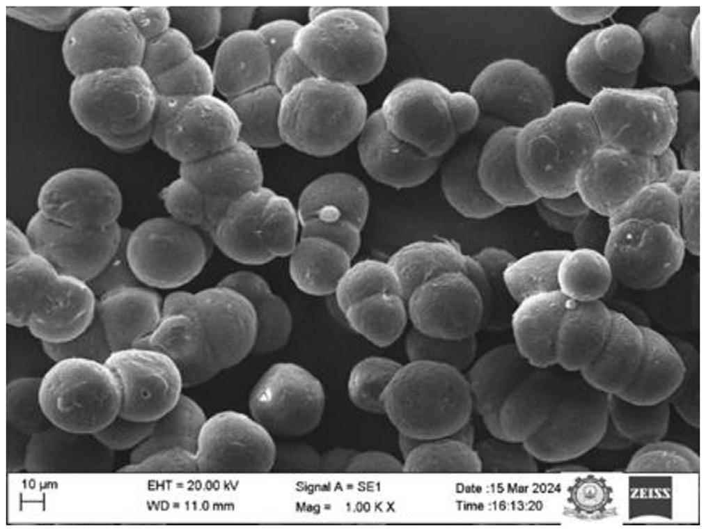
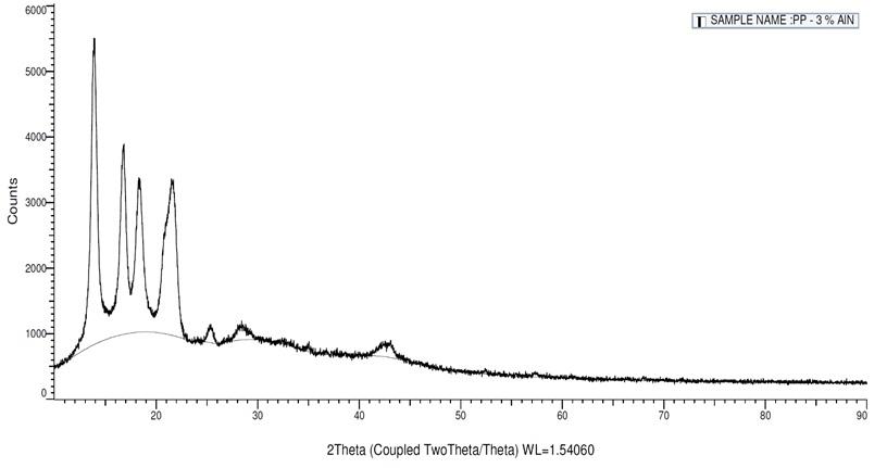
Subramaniam, S., & Veerayan, M. B.
the PP+3% MgO sample showed sharper and more distinct MgO peaks, implying relatively larger crystallite domains and slightly less interfacial distortion within the polymer network. This difference in peak sharpness and intensity may indicate that AlN particles are more uniformly dispersed and better integrated within the PP matrix than MgO at the same concentration. The suppression of peak intensity and slight broadening for both nanocomposites also suggest reduced PP crystallinity, potentially due to the physical obstruction and nucleation effects of the nanoparticles.
The improved crystallinity at 3 wt% MgO and 3 wt% AlN enhances mechanical stability, thermal resistance, and dielectric uniformity, all of which are critical properties for HVDC insulation applications. This optimal concentration ensures a balance between filler-induced nucleation and matrix compatibility, minimizing interfacial defects and enhancing long-term insulation reliability.
3.1 AC breakdown test
The AC breakdown strength of the prepared polypropylene (PP) nanocomposite films was evaluated using a sphere-to-sphere electrode configuration. Samples with a uniform thickness of 100 μm were immersed in silicone oil during testing to eliminate surface discharges and prevent flashover due to air exposure. A total of twenty measurement points were marked on each sample, ensuring consistent and statistically valid data. The samples were positioned carefully between the spherical electrodes, and AC voltage was applied at a ramp rate of 1 kV/s until dielectric failure occurred. The average breakdown voltage was recorded from multiple locations for each sample to obtain a reliable measure of dielectric strength. The results are presented in Figure 11
Among the samples tested, PP + 3 wt% MgO exhibited the highest breakdown strength of 226.8 kV/mm, representing a 13.82% improvement over pure PP. Similarly, PP + 5 wt% MgO showed a breakdown strength of 219.24 kV/mm, which is 10.44% higher than that of the unfilled matrix. In contrast, PP + 2 wt% MgO yielded a slightly lower value of 185.71 kV/mm, approximately 6.14% below that of pure PP, likely due to particle agglomeration at this intermediate concentration.
For AlN-based composites, PP + 3 wt% AlN demonstrated a maximum breakdown strength of 230.34 kV/mm, reflecting a 15.4% enhancement over neat PP. However, the breakdown strength significantly declined with increased filler content. PP + 2 wt% AlN and PP + 5 wt% AlN exhibited lower values of 151.62 kV/mm and 172.83 kV/mm, which are 26.27% and 13.31% lower than that of pure PP, respectively. These reductions are attributed to filler agglomeration, which introduces interfacial defects, promotes localized electric field enhancement, and degrades dielectric performance at higher loading levels.
To further interpret the statistical variability of breakdown behavior, the Weibull probability distribution function was applied, expressed as:
where:
E : the measured value of electric field at the different point of the sample;
E0: the critical parameter of the breakdown for a probability of 63.2%;
β : the Weibull distribution shape parameter of the dielectric strength.
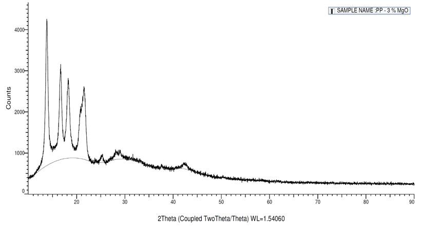
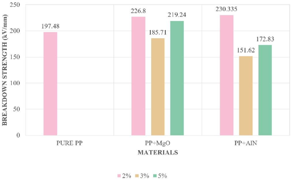
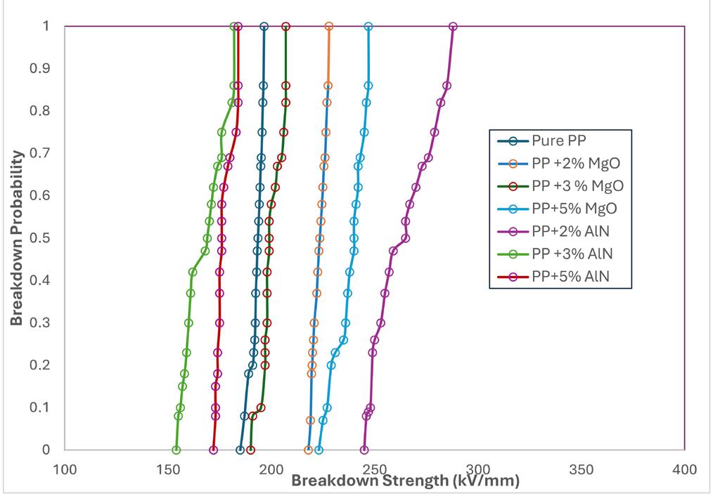
Comparative analysis of nitride and oxide based nano fillers for polypropylene
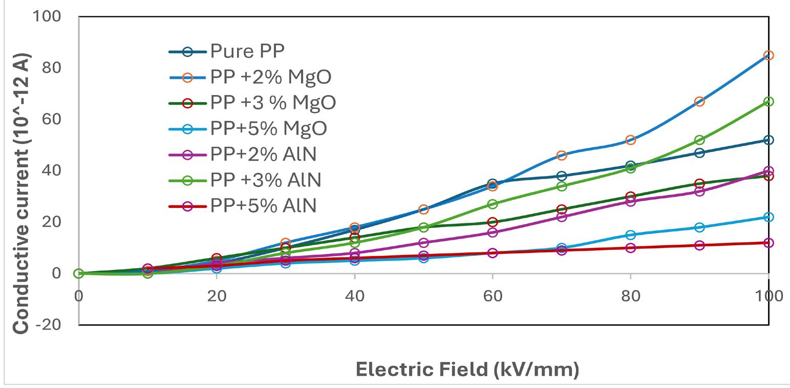
The Weibull model provides valuable insights into the reliability and uniformity of dielectric breakdown across the composite samples as shown in Figure 12. A higher β-value indicates narrower distribution and greater reliability, which can be correlated with better filler dispersion and interfacial bonding.
Overall, the results suggest that 3 wt% MgO and 3 wt% AlN are the optimal concentrations for enhancing AC breakdown strength, owing to a balance between improved crystallinity, dielectric uniformity, and minimal filler agglomeration. These findings demonstrate the potential of MgO and AlN-filled PP nanocomposites for high-voltage insulation applications in HVDC cables.
The DC volume conductivity of the polypropylene (PP) nanocomposite films was measured using a digital high-resolution electrometer (Keithley) integrated with a standard three-electrode system, as per established protocols. The nanocomposite films, including PP/MgO and PP/AlN samples with a uniform thickness of 100 μm, were subjected to DC electric fields ranging from 10 kV/mm to 100 kV/mm, applied in incremental steps of 10 kV/mm. Each voltage increment was maintained for 2 minutes, allowing the system to reach a quasi-steady-state condition before current measurement. Prior to the test, all samples were short-circuited for 10 minutes to eliminate any residual charge and ensure accurate baseline measurements.
This test procedure enabled the evaluation of the impact of nano-fillers on the bulk electrical conductivity of PP under high-field stress conditions[17]. The incorporation of nano-MgO and nano-AlN is expected to influence charge carrier mobility, trap density, and interfacial polarization effects, all of which contribute to the overall electrical resistivity of the composite.
The conductivity results, discussed in the following section, demonstrate how nano-filler type and concentration affect the DC volume resistivity of PP as shown in Figure 13 Improved dispersion and strong filler–matrix interactions at optimal loading (notably at 2–3 wt%) resulted in reduced leakage current and enhanced dielectric behavior, mak-
ing these nanocomposites suitable candidates for HVDC insulation applications.
Polypropylene (PP), owing to its high breakdown strength, elevated melting point, and recyclability, presents itself as a promising candidate for high-voltage direct current (HVDC) cable insulation. In this study, the incorporation of nano-scale oxide (MgO) and nitride (AlN) fillers into the PP matrix was investigated to evaluate their influence on the electrical properties of the resulting nanocomposites.
The results reveal that the breakdown strength of PP improved significantly at optimal filler concentrations. Specifically, the PP + 3 wt% AlN composite exhibited a maximum breakdown strength of 230.33 kV/mm, representing a 15.4% increase over pure PP. Similarly, the PP + 3 wt% MgO sample achieved a breakdown strength of 226.8 kV/mm, which is 13.82% higher than that of unmodified PP. However, further increasing the filler content beyond 3 wt% led to a decline in dielectric performance, likely due to agglomeration effects and interfacial imperfections.
Moreover, DC conductivity measurements confirmed that the addition of nano-fillers effectively reduced the conductivity of the composites, contributing to improved insulation performance. This reduction can be attributed to enhanced charge trapping and increased interfacial barriers introduced by the dispersed nano-fillers.
In conclusion, the study demonstrates that 3 wt% of AlN or MgO in a PP matrix offers an optimal balance of electrical properties, making these nanocomposites strong candidates for use in next-generation HVDC insulation systems. Future work may focus on long-term thermal aging, space charge behavior, and mechanical robustness to further validate field performance.
• Conceptualization – Sundaramahalingam Subramaniam; Manikandan Bairavan Veerayan.
Subramaniam, S., & Veerayan, M. B.
• Data curation – Sundaramahalingam Subramaniam; Manikandan Bairavan Veerayan.
• Formal analysis – Sundaramahalingam Subramaniam; Manikandan Bairavan Veerayan.
• Funding acquisition – NA.
• Investigation – Sundaramahalingam Subramaniam; Manikandan Bairavan Veerayan.
• Methodology – Sundaramahalingam Subramaniam; Manikandan Bairavan Veerayan.
• Project administration – NA.
• Resources – Sundaramahalingam Subramaniam.
• Software – NA.
• Supervision – Manikandan Bairavan Veerayan.
• Validation – Manikandan Bairavan Veerayan.
• Visualization – Sundaramahalingam Subramaniam.
• Writing – original draft – Sundaramahalingam Subramaniam.
• Writing – review & editing – Manikandan Bairavan Veerayan.
6. Acknowledgements
We extend our gratitude to Mepco Schlenk Engineering College and Kalasalingam University for providing necessary facilities for the successful completion of the work.
7. References
1 Huang, X., Fan, Y., Zhang, J., & Jiang, P. (2017). Polypropylene based thermoplastic polymers for potential recyclable HVDC cable insulation applications. IEEE Transactions on Dielectrics and Electrical Insulation, 24(3), 1446-1456 https:// doi.org/10.1109/TDEI.2017.006230.
2 Andritsch, T., Vaughan, A. S., & Stevens, G. C. (2017). Novel insu-lation materials for high voltage cable systems. IEEE Electrical Insulation Magazine , 33(4), 27-33. https://doi. org/10.1109/MEI.2017.7956630
3 Wang, X., Andritsch, T., Chen, G., & Virtanen, S. (2019). The role ofthe filler surface chemistry on the dielectric and thermal properties of polypropylene aluminium nitride nanocom-posites. IEEE Transactions on Dielectrics and Electrical Insulation, 26(3), 1009-1017. https://doi.org/10.1109/TDEI.2019.007773.
4 Du, B. X., Xu, H., & Li, H. (2017). Effects of mechanical stretching on space charge behaviors of PP/POE blend for HVDC cables. IEEE Transactions on Dielectrics and Electrical Insulation, 24(3), 1438-1445 https://doi.org/10.1109/ TDEI.2017.006116
5. Guo, Y., Ruan, K., Shi, X., Yang, X., & Gu, J. (2020). Factors affecting thermal conductivities of the polymers and polymer composites: A review. Composites Science and Technology, 193(2), 108134. https://doi.org/10.1016/j.compscitech.2020.108134.
6 Li, Z., Cao, W., Sheng, G., Jiang, X., & Danikas, M. G. (2016). Experimental study on space charge and electrical strength of MgO nano-particles/polypropylene composite. IEEE Transactions on Dielectrics and Electrical Insulation, 23(3), 1812-1819 https://doi.org/10.1109/TDEI.2016.005181
7 Li, J., Yang, K., Wu, K., Jing, Z., & Dong, J.-Y. (2023). Ecofriendly polypropylene power cable insulation: present status and perspective. IET Nanodielectrics, 6(1), 130-140 https:// doi.org/10.1049/nde2.12048
8. Azrin, N. A., Ahmad, N. A., Lau, K. Y., & Kamarudin, S. N. H. (2024). Structure, mechanical, and dielectric properties of polypropylene blended with ethylene and propylene‐based elastomers. Journal of Applied Polymer Science, 141(41), e56060 https://doi.org/10.1002/app.56060
9. Mazumder, M. R. H., Mathews, L. D., Mateti, S., Salim, N. V., Parameswaranpillai, J., Govindaraj, P., & Hameed, N. (2022). Boron nitride based polymer nanocomposites for heat dissipation and thermal management applications. Applied Materials Today, 29, 101672 https://doi.org/10.1016/j. apmt.2022.101672
10 Ruan, H., Lü, F., Song, J., Bian, X., Yin, K., Yin, S., & Xie, Q. (2022). Enhanced thermal conductance and electrical insulation of AlN/PMIA composite paper via nano splitting of matrix and size grading of fillers. Composites Science and Technology, 224, 109477 https://doi.org/10.1016/j.compscitech.2022.109477
11. Wu, Y., Li, Z., Wang, H., Zheng, Z., & Du, B. (2024). Enhanced dielectric breakdown property of polypropylene based on mesoscopic structure modulation by crystal phase transformation for high voltage power cable insulation. ACS Applied Polymer Materials, 6(5), 3031-3041 https://doi.org/10.1021/ acsapm.4c00251
12 Du, B., Liu, H., & Li, Z. (2023). Effect of Nucleating agent and cooling rate on dielectric property of PP/POE Cable insulation. IEEE Transactions on Dielectrics and Electrical Insulation , 31 ( 2 ), 929 - 936 https://doi.org/10.1109/ TDEI.2023.3330694
13 Hosier, I. L., Vaughan, A. S., Pye, A., & Stevens, G. C. (2019). High performance polymer blend systems for HVDC applications. IEEE Transactions on Dielectrics and Electrical Insulation, 26(4), 1197-1203 https://doi.org/10.1109/TDEI.2019.007954
14 Hosier, I. L., Praeger, M., Holt, A. F., Vaughan, A. S., & Swingler, S. G. (2017). On the effect of functionalizer chain length and water content in polyethylene/silica nanocomposites: Part I - Dielectric properties and breakdown strength. IEEE Transactions on Dielectrics and Electrical Insulation, 24(3), 1698-1707 https://doi.org/10.1109/TDEI.2017.005788
15. Cao, W., Li, Z., Sheng, G., & Jiang, X. (2017). Insulating property of polypropylene nanocomposites filled with Nano-MgO of different concentration. IEEE Transactions on Dielectrics and Electrical Insulation, 24(3), 1430-1437. https://doi.org/10.1109/ TDEI.2017.006015
16 Zhou, Y., He, J., Hu, J., & Dang, B. (2016). Surface-modified MgO nanoparticle enhances the mechanical and direct-current electrical characteristics of polypropylene/polyolefin elastomer nano-dielectrics. Journal of Applied Polymer Science, 133(1), 42863 https://doi.org/10.1002/app.42863
17 Cheng, L., Chi, X., Yan, C., Xie, D., Liu, X., Wen, Y., Liu, W., & Li, S. (2018). Polypropylene nanocomposite for power equipment: a review. IET Nanodielectrics, 1(2), 92-103 https:// doi.org/10.1049/iet-nde.2018.0005
Received: Feb. 06, 2025
Revised: Jul. 05, 2025
Accepted: Oct. 08, 2025
Editor-in-Chief: Sebastião V. Canevarolo
Vanessa Machado Babinski Ramos1*
,
Eliseu Rodrigues2
and Ruth Marlene Campomanes Santana1
1Laboratório de Materiais Poliméricos – LAPOL, Programa de Pós-graduação em Engenharia de Minas, Metalúrgica e de Materiais – PPGE3M, Universidade Federal do Rio Grande do Sul – UFRGS, Porto Alegre, RS, Brasil
2Instituto de Ciência e Tecnologia de Alimentos – ICTA, Universidade Federal do Rio Grande do Sul –UFRGS, Porto Alegre, RS, Brasil
*vanessa.machadoramos@gmail.com
Obstract
This study developed active low-density polyethylene (LDPE) packaging incorporating natural antioxidants from wine industry residues and compared them with synthetic antioxidant (BHT). The antioxidant extract (AE), obtained from wine residues, contained 15 phenolic compounds, with catechin (30.51 mg/100g) and epicatechin (22.40 mg/100g) as major flavonoids. Packaging films were produced via extrusion and characterized by FTIR, colorimetry and thermogravimetric analysis. The FE1 active packaging formulation with 12% AE, showed reduced light transmission and improved thermal stability. In peroxide index tests, FE1 preserved sunflower oil below the legal oxidation limit (10 mEq/kg) for up to 5 days, reduced oxidation by 67.90% compared to standard LDPE packaging and 67.71% compared to BHT packaging, maintaining peroxide levels below regulatory limits for a longer duration.The results indicate that incorporating natural antioxidant extracts into LDPE creates active packaging with promising antioxidant properties, with potential for developing innovative solutions through extrusion processes using residues from wine industry.
Keywords: active packaging, agro-industrial waste, natural antioxidant, polyethylene.
Data Ovailability: All data supporting the findings of this study are available from the corresponding author upon request.
How to cite: Ramos, V. M. B., Rodrigues, E., & Santana, R. M. C. (2026). Development of active LDPE packaging with antioxidants from agro-industrial wine waste. Polímeros: Ciência e Tecnologia, 36(1), e20260003. https://doi.org/10.1590/0104-1428.20250064
Food spoilage is responsible for the loss of quality and food safety and can occur during production, transportation, processing or storage. Oxidation is a major cause, reducing shelf life by degrading essential nutrients, altering color and odor, and forming harmful compounds like trans isomers[1]. Packaging serves as a crucial barrier, protecting food from external factors like oxygen, moisture, light, and contamination[2]
The main raw material for food packaging is thermoplastic materials, and in this context, polyethylene (PE) stands out in packaging production[3]. New technologies in the packaging area aim to interact with the food product, in order to modify or maintain product quality parameters. Among the innovations are active packaging, which consists of incorporating functional components into the packaging that release or absorb substances into the packaged food or the environment, extending its useful life[4]. The concept of active packaging encompasses several technologies, such as oxygen and humidity absorbers, modified atmosphere, CO2 emitters, ethylene absorbers, among others[5]
Among the most important active packaging are the antioxidant active packaging, which has a protective effect against oxidation of the packaged product, as it aims to remove any residual oxygen present in the packaging or improve barrier properties, acting as an active barrier[6]. Its use also allows the production of foods with less addition of synthetic antioxidants. Synthetic antioxidants are widely used to delay oxidation, but concerns over their toxicological effects have led to growing interest in natural alternatives, such as plant-based extracts[7].
Agro-industrial residues are of economic and environmental interest as sources of natural antioxidants, as many of them are rich in bioactive and antioxidant compounds. Although some are used as animal feed or field disposal, most are discarded untreated, contributing to environmental and economic issues in the production chain[8].
The wine industry generates significant by-products, including grape pomace, skins and seeds. In Brazil, wine production exceeded 800 million liters in 2023, resulting in approximately 200.000 tons of grape pomace as agro-
industrial waste[9]. These by-products, mainly seeds and peels, are rich in phenolic compounds (60% in seeds, followed by 30% in skin and 10% in pulp), responsible for their high antioxidant activity. Producers and wineries face the problem of disposing of residual biomass, which, although biodegradable, requires a minimum amount of time to be mineralized, becoming a source of pollutants. The possibility of obtaining phenolic compounds through a process of extracting these residues, and using them as natural antioxidant additives in polymeric films for active packaging, has attracted considerable attention[10].
Given the growing global emphasis on sustainability, current research in food packaging has increasingly focused on the development of materials that minimize environmental impact. The present study gains relevance by proposing the incorporation of antioxidants from agro-industrial wine waste—an abundant and underutilized by-product—into LDPE for active packaging. This approach aligns with sustainability goals by valorizing waste, reducing dependence on synthetic additives and advancing green technologies in polymer processing. Despite existing studies on chemical antioxidants used to protect polymers during processing, few have explored polyolefin films with natural antioxidants capable of interact with the food or product to be packaged, highlighting the novelty and potential of this research.
2.1 Chemicals
Standards of caffeic and galic acid, (+)-catechin, (-)-epicatechin, cianidin and quercetin were purchased from Sigma-Aldrich (St. Louis, MO). Acetonitrile and methanol both of HPLC grade were from Honeywell (Charlotte, North Carolina, USA). Formic acid was purchased from Merck (Darmstadt, Germany). Methanol (P.A.) was purchased from Neon Comercial (São Paulo, Brazil). Ethanol was purchased from Êxodo Cientifica (São Paulo, Brazil). Ultrapure water (Milli-Q) was generated by the Millipore System (Molsheim, FR). The synthetic antioxidant used was BHT [2,6-bis(1,1dimethylethyl)-4-methylphenol] from Adicel (Belo Horizonte, Brazil). Maleic anhydride Polybond 3009, was purchased from SI Group (The Woodlands, USA).
2.2 Agro-industrial
The wine residue, consisting of skins and seeds from Vitis labrusca (Isabel grape), was supplied by a small winery in Bento Gonçalves-RS. To preserve phenolic compounds, the 5kg of residue was frozen at -80 °C, freeze-dried (Liobras model L101 equipment), milled, and vacuum-packed. To obtain the antioxidant-rich extract, 50 g of freeze-dried wine residue was subjected to exhaustive solid-liquid extraction using 250 mL of ethanol:water (80:20 v/v) acidified with 1.5% formic acid, in a centrifuge-compatible container.
The sample with solvent was stirred for 5 minutes using a vortex shaker (VELP ZX3), then centrifuged at 3000 g (10 min) in a refrigerated high-speed centrifuge (Hitachi CR 21GIII), as adapted from the methodology described by Selani et al.[11] and Lorrain et al.[12]. The supernatant at each stage of the exhaustive extraction process was collected in an amber bottle. The supernatant was concentrated in a
rotary vacuum evaporator at 40 °C, until all the solvent was evaporated. The antioxidant extract (AE) was frozen at -18 °C, freeze-dried, and stored in amber bottles at -18 °C until use in active packaging preparation.
The analysis of phenolic compounds from the AE was carried out using HPLC (High Performance Liquid Chromatography) equipment, Shimadzu (Kyoto, Japan), which has a diode array detector (DAD) and is connected to the mass spectrometer (Bruker Daltonics, microOTOF-Q III model). The phenolic compounds separation was carried out using a Phenomex Synergi C18 (250 mm × 4.6 mm, 4 µm), with a flow rate of 0.7 L min-1[12]. The mobile phase used in linear gradient consisted of water + 0.1% formic acid (mobile phase A) and acetonitrile + 0.1% formic acid (mobile phase B). The spectra were obtained at wavelengths of 280 nm, 320 nm, 360 nm and 520 nm.
After separating the phenolic compounds in the LC, the column eluate was divided using a “T” connection, in which 0.35 mL.min-1 of the flow went to the MS. The ESI source was operated in negative and positive ionization modes, scan range from m/z 50 to 1000, capillary voltage of 3000 volts, drying gas (N2) temperature and flow of 310 °C and 8 L.min-1, nebulizer gas pressure of 4 bar. Phenolic compounds were identified by manual interpretation based on C18 column elution order, UV-VIS spectra, exact mass, and fragmentation patterns, compared with standards and literature data. Quantifications of phenolic compounds were carried out using the analytical curves of six phenolic standards (gallic acid, caffeic acid, catechin, epicatechin, cyanidin and quercetin).
The polymeric matrix selected for the production of antioxidant active packaging was Low Density Polyethylene (LDPE), commonly used for extrusion of tubular films for food packaging, with a melt flow index of 2.7g.10min-1 at 190 °C/2.16kg and density of 0.923g/cm3. To produce active packaging, masterbatches were prepared by incorporating the AE into LDPE using a Haake Rheomix OS – Thermo Scientific extruder.
Three formulations were developed: ME1-Masterbatch with LDPE and more concentrated AE masterbatch, ME2-Masterbatch with LDPE and less concentrated AE masterbatch, and MR1-Masterbatch with LDPE and Freezedried wine residue.
A HDPE grafted with maleic anhydride (PEgAm), Polybond 3009 from Addivant, was used as a compatibilizing agent in order to reduce the interfacial energy between the additives and the polymer matrix and improve their dispersion[13]. The LDPE and compatibilizing agent were first added to Haake, and processed for 4 minutes at 160 °C and then the antioxidants were added to mix until 5 minutes were completed. The formulations of masterbatches produced with a compatibilizing agent are described in Table 1
The percentage of AE, Freeze-dried wine residue and PEgAm added to the LDPE in the masterbatch formulations, were based on preliminary tests did on Haake equipment and processing limitations. Based on the literature described by
Development of active LDPE packaging with antioxidants from agro-industrial wine waste
Martins et al.[14], Chen et al.[15], Duran et al.[16], different mass percentages (w/w%) of antioxidant extracts can be added to polymeric materials in the production of active packaging, and the most common addition ranges are between 0.5% to 8%. For the production of active packaging, formulations were prepared with LDPE and 5% w/w of the previously produced masterbatches.
The mixtures were processed using an AX Plásticos extruder - Mini Extruder AX DR 16:40, double counterrotating screw, diameter of 16mm L/D of 40, mass pressure of 59 bar, and the feeder and screw rotations were 12,6 rpm and 12,1 rpm, respectively. Extrusion was carried out with temperature ranges (Zone 1 – 140 °C, Zone 2 – 150 °C, Zone 3 – 160 °C, Zone 4 – 160 °C, Zone 5 – 165 °C, Zone 6 –170 °C, Zone 7 – 180 °C, Zone 8 – 180 °C, Zone 9 – 185 °C), to produce films with ~40 µm thickness. For comparative purposes, a reference sample with only LDPE, a sample with BHT (FE3), samples with masterbatches of natural AE (FE1-high concentration and FE2-low concentration), and a sample with freeze-dried wine residue (FE4) were extruded under the same experimental conditions.
In Table 2 the identification and description of the active packaging samples produced are represented.
To evaluate the colorimetric properties of active packaging films, color analysis was carried out using a Spectro-Guide portable spectrophotometer (BYK brand, Sphere Gloss model). The analyzes were carried out using the CIELAB color system, from the International Commission on Illumination. In the CIELab system, colors can be decomposed into 3 independent orthogonal parameters, L*, a* and b*.
2.6
Fourier transform infrared spectroscopy (FTIR) was used to investigate the surface species of the film samples. Spectra were collected in H-ATR (Horizontal Attenuated Total Reflectance Accessory) mode in accordance with ASTM E1252-2021[17]. Analyzes in transmission mode
Table 1. Masterbatch formulations.
were performed on a Perkin Elmer FTIR spectrophotometer (model Spectrum 1000). Spectra were collected with 32 scans, 4 cm−1 resolution, over 4000-600 cm−1
The peroxide index analysis was carried out according to the IUPAC methodology[18], also referenced by the Analytical Standards of the Adolfo Lutz Institute[19]. The formulations selected were LDPE, FE1 and FE3, to carry out a comparison between the use of extract versus synthetic antioxidants in active packaging. A control sample of unpackaged sunflower oil in a Petri dish was also analyzed.
The film samples in the form of sachets containing 8 mL of antioxidant-free sunflower oil were sealed and exposed to UV radiation chamber (4000-5000 lux, 40 °C, 50% RH) under accelerated conditions. After preparing samples for 7 days monitoring and recording initial readings, the sachets were placed in the chamber.
For analysis, 5 g of oil from sachets was mixed with 30 mL acetic acid:chloroform (3:2), stirred until the sample dissolved and then 0.5 mL of a saturated solution of potassium iodide, 30 mL of distilled water and 1.0 mL of 1% aqueous starch solution were added. The mixture was titrated with 0.1 N sodium thiosulfate until colorless. Tests were done in triplicate. In parallel, a blank test was conducted, without the oil sample. Sachets were removed after 2, 5, 7, 10, 12, 17, and 20 days for peroxide index analysis. To calculate the peroxide index, reported in meq/1000g of sample, the Equation 1 was used. ( ) 1000 1000 mequivalent
where: A = volume in mL of the Na2SO2O3 solution used for the sample; B = volume in mL of the Na2SO2O3 solution used for the blank; N = normality of the Na2SO2O3 solution; f = correction factor for 0.1N sodium thiosulfate solution. P = weight in grams of the sample.
ME1 = Masterbatch with LDPE and 12% w/w antioxidant extract; ME2 = Masterbatch with LDPE and 5% w/w antioxidant extract; MR1 = Masterbatch with LDPE and 5% w/w of Freeze-dried wine residue in natura
Table 2. Active packaging formulations.
FE1 = Formulation 1 with LDPE and 5%w/w ME1 masterbatch; FE2 = Formulation 2 with LDPE and 5% w/w ME2 masterbatch; FE3 = Formulation 3 with LDPE and 5%w/w of BHT; FE4 = Formulation 4 with LDPE and 5%w/w MR1 masterbatch.
3.1 Antioxidant extract (AE) phenolic composition
A total of 15 phenolic compounds were identified in the ethanolic extract and 14 compounds in methanolic extract. The fifteen phenolic compounds found in the extract are shown in Table 3. Additional experimental data are provided in the Supplementary Material (Tables S1 and S2).
The AE is mainly formed by flavonoids, such as catechin and epicatechin. Anthocyanins represent the second most important class in terms of concentration in the AE. Eight anthocyanins were found, highlighting delphinidin 3-O-(6O-p-coumaryl)glucoside, delphinidin 3-O-hexoside and petunidin 3-O-hexoside.
3.2 Characterization of masterbatches and wine residue
3.2.1 Thermogravimetric analysis (TGA)
The thermogravimetric curves (TGA) and derived thermogravimetric curves (DTG) are represented in Figure 1,
in which results regarding the decomposition of the evaluated samples can be obtained.
Mass loss up to 100 °C indicates sample moisture. The freeze-dried waste showed peaks at 207 °C and 354 °C, which may be associated to hemicellulose and cellulose decomposition[20,21] respectively. Between 400-500 °C the LDPE, ME1, ME2, and MR1 samples exhibited mass losses typical of LDPE decomposition[22]. Above 900 °C, the freeze-dried residue presented a residue of 17.03%, suggesting inorganic fillers, possibly silica from grape skin fibers, similar to açaí fibers[23].
The samples that contain an AE (ME1 and ME2), showed greater thermal stability when compared to the LDPE reference sample, suggesting that the presence of these compounds provides greater resistance to degradation. The residual masses between ME1 and ME2 were similar up to 350 °C, however, from the degradation temperature of pure LDPE, approximately at 474 °C, a change in thermal stability was observed, where the ME1 sample contains a greater amount of AE than ME2, showed greater resistance to degradation.
3-O-hexozide
Peonidin 3-O-hexozide
Malvidin 3-O-glucoside
3-O-hexoside
Delphinidin 3-O-(6-O-p-coumaryl)glucoside
Cyanidin 3-(6-O-p-coumaryl)glucoside
Malvidin 3-O-(6-O-p-coumaryl)glucoside
aQuantified in gallic acid. bQuantified in caffeic acid. cQuantified in Cyanidine. dQuantified in Catechin. eQuantified in (-) Epicatechin. fQuantified in Quercetin.
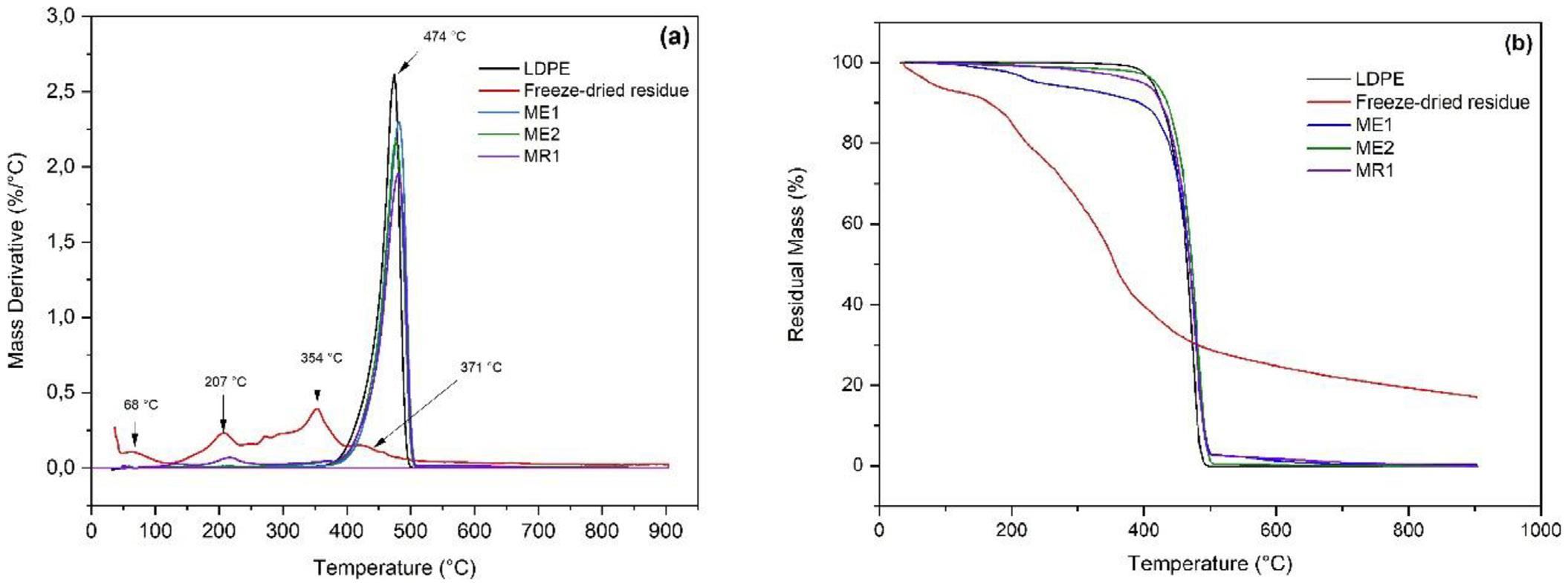
1. (a) Mass derivative × Temperature of the evaluated samples; (b) Residual Mass × Temperature of the evaluated samples.
Development
Thermal degradation began at temperatures higher than those used during mixing and extrusion, indicating that conventional processing conditions are suitable and do not compromise material stability for active packaging production.
3.3.1
The Figure 2 represents the films produced and their respective identifications.
In Table 4, the results related to the color parameters (L*, a* and b*) of the formulations are presented.
The luminosity parameter L* showed a decrease in the FE1 and FE2 formulations, when compared to the LDPE reference sample. These lower luminosity results are related to the addition of masterbatches with AE (anthocyanins compounds), which reduces the passage of UV/Vis light, a behavior also observed in the study with the addition of freeze-dried grape residue in the production of polymeric biocompounds[24].
The formulation with synthetic antioxidant, FE3, did not show significant differences when compared to the reference sample, because the BHT is colorless. The FE4 formulation did not have its luminosity affected by the incorporation of freeze-dried wine residue (p> 0.05). The change in color intensity in the FE1 and FE2 films, in parameters a* and b*, are related to the anthocyanins from the AE added to these formulations, so that the color of the films intensifies with the increase in the anthocyanin content.
The variation in the b* parameter for the yellow scale in sample FE1 may be related to the shear stress that the sample suffered during the preparation of the masterbatch, as
it was subjected to two passes through the Haake extruder to reach the final concentration, unlike the masterbatch of the FE2 formulation, which passed through the extruder only once. Thermo-mechanical processing results in degradation of the mixture and change in color (yellowish color). The superior result of the parameter b* (yellow) in sample FE1 may also indicate the presence of pigments derived from the thermal degradation of grape skin constituents, mainly phenolic compounds and lignocellulosic material[25]
The characterization of films for active packaging and standard film was carried out using the Fourier Transform Infrared Spectroscopy (FTIR) technique, in transmission mode. The Figure 3 presents the FTIR spectra of the analyzed samples.
The FTIR spectra showed characteristic bands at of 2915 cm-1 and 2847 cm-1, attributed to the ѵCsp3-H stretching, characteristic of aliphatic hydrocarbons originating from LDPE[26 27]. In Figure 4, the bands in the region of 1600 to 1200 cm-1 are presented with magnification, for better visualization.
The peaks observed at 1634 cm-1 in Figure 4 for samples containing wine residue FE1, FE2 and FE4, are related to the stretching of the aromatic ring (C=C and –OH) of the functional groups present in the phenolic compounds[21]
The intense band at 1465 cm-1 can be attributed to deformations of methylene δCH2, present in the polyolefin used to produce the films. The bands at 1375 cm-1 and 1300 cm-1 refer respectively to symmetric deformation of the methyl (terminal low-density methyl) and C-C vibrations.
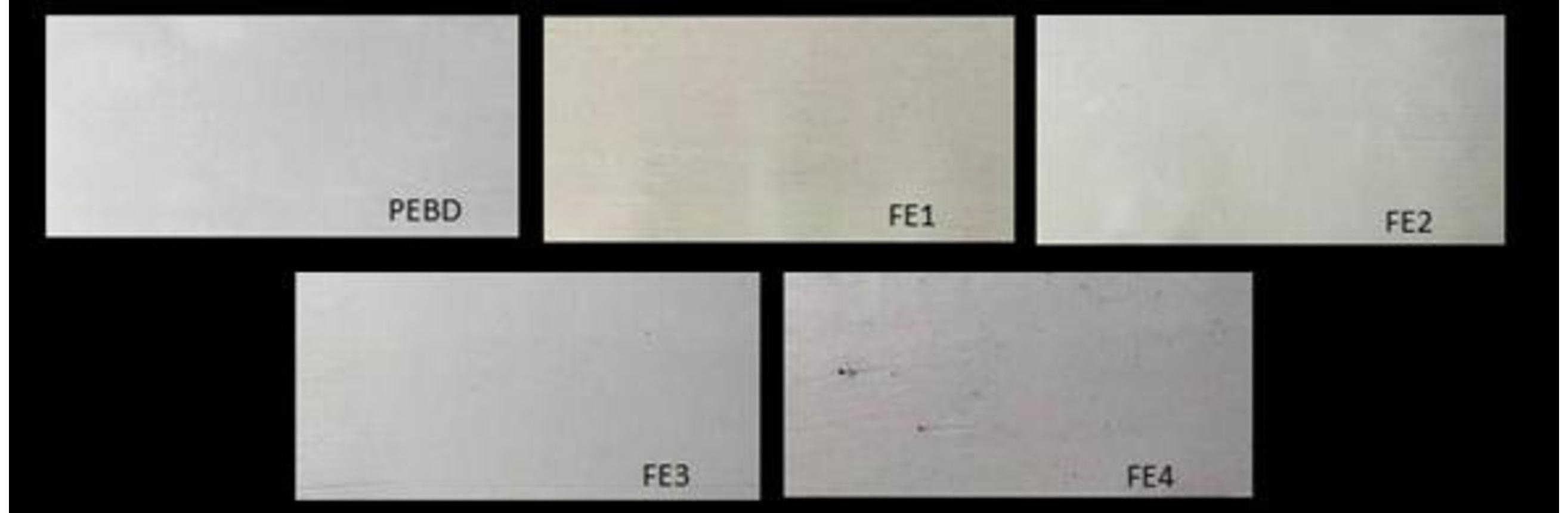
Equal letters indicate that there is no significant difference with 95% confidence according to the Tukey test. LDPE = low-density polyethylene formulation; FE1 = Formulation 1 with LDPE and more concentrated AE masterbatch; FE2 = Formulation 2 with LDPE and less concentrated AE masterbatch; FE3 = Formulation 3 with LDPE and synthetic antioxidant BHT; FE4 = Formulation 4 with LDPE and masterbatch with freeze-dried residue.
V. M. B., Rodrigues, E., & Santana, R. M. C.
3.3.3 Peroxide index and antioxidant activity of active packaging
The peroxide index was carried out to verify the effect of using polyethylene film and active packaging produced with AE and synthetic antioxidants on the oxidation of fresh sunflower oil. The results are presented in Table 5
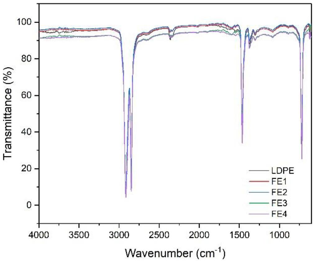
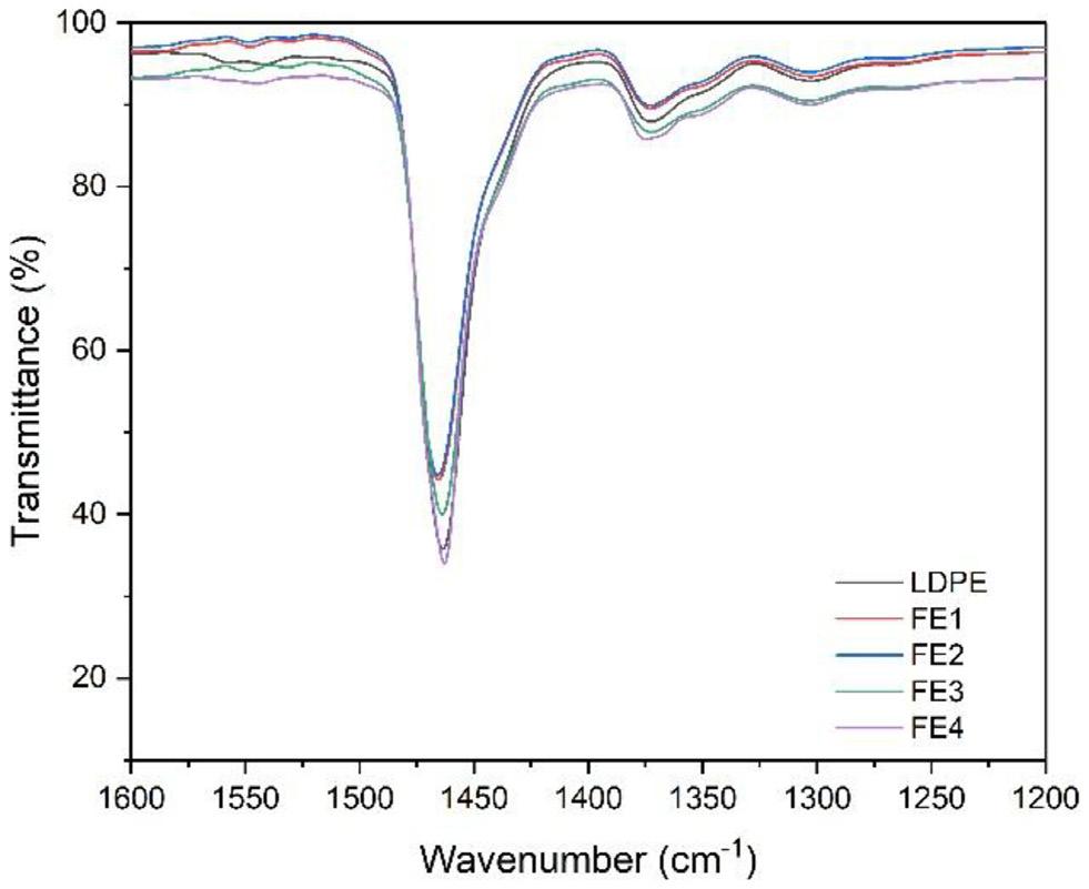
The Figure 5 shows the stability of sunflower oil under oxidizing conditions, with a significant increase (p < 0.05) in the peroxide index after 20 days of storage in a UV chamber.
According to Codex Standard-1999[28] and Resolutionrdc nº 270 of the National Health Surveillance Agency[29] , the maximum value of Peroxide index allowed for the commercialization of refined oils and fats is 10 mEq peroxides. kg-1 of sample. The control sample (sunflower oil without packaging), reached 14 mEq of peroxides.kg-1 of sample, after 2 days in direct contact with oxygen, temperature and absence of a light barrier. The control sample showed faster and greater oxidation compared to the LDPE, FE1 and FE3 formulations. This behavior for fresh sunflower oil was also reported in the study of biodegradable cellulose acetate packaging incorporated with norbixin, lycopene and zeaxanthin[30], and with starch-based antioxidant films with encapsulated eugenol[31]
From the 2nd day of testing, the unpackaged oil, LDPE and FE3 samples exceeded the limit of 10 mEq peroxides. kg-1 of sample. In relation to the peroxide index limit established in the legislation, only the oil sample protected with the active packaging formulation FE1 was suitable for consumption after 2 and 5 days of exposure.
The FE1 formulation had in its composition a natural AE consisting mainly of flavonoids of the flavan-3-ol type, highlighting catechin and (-)-epicatechin. The antioxidant effect of this active packaging may be associated with the primary mechanism of flavonoids to deactivate radicals formed during the propagation stage of lipid oxidation. Furthermore, flavonoids are able to chelate transition metals, which will decrease the rate of lipid oxidation. The flavonoids have chelating properties, which allow them to chelate, or bind to, metal ions to prevent them from being accessible for oxidation and the formation of free radicals[32]
The FE1 packaging showed lower luminosity (L) and higher color parameters (a*, b*), which reduced light transmission and therefore limited photooxidation of sunflower oil. This is due to the anthocyanins present in the extract (color filter) or their degradation products, which acted as filters for the passage of electromagnetic radiation.
On the 5th day of evaluation, the control sample showed higher peroxide index results than all other samples analyzed. These results may also be associated with the films having the property of oxygen permeability.
Equal letters indicate that there is no significant difference with 95% confidence according to the Tukey test. Statistical analysis was performed comparing Day n x Samples.
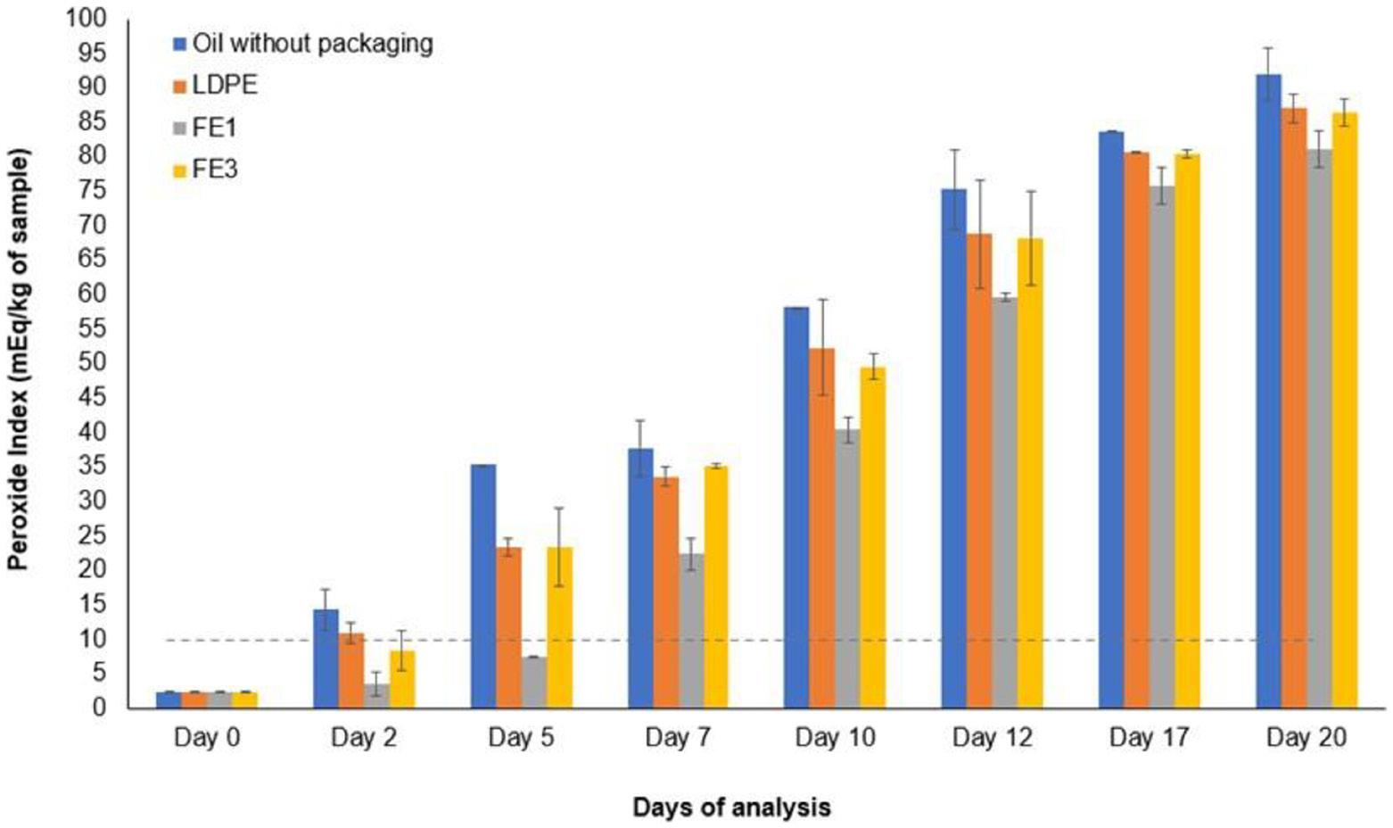
The permeability of gases through polymers is influenced by factors like polymer type, film thickness, penetrant characteristics, pressure, and temperature. Inert gases such as oxygen interact minimally with polymers, resulting in low absorption and no structural changes. Their permeation is mainly determined by the polymer’s structural features, including polarity, unsaturation, and side chains. The LDPE formulations in general present a lower barrier, and consequently higher oxygen permeability results, than formulations with HDPE. The presence of long branches in LDPE makes the packaging of macromolecules difficult, resulting in an increase in free volume and greater permeability[33]. The barrier created by LDPE films may have helped to reduce the oxygen permeability process for the food.
Among the films, on the 5th day of analysis, FE1 formulation showed lower peroxide index results, 78.67% lower than the Oil sample without packaging, 67.90% lower than LDPE and 67.71% lower than FE3.
On the 7th day of analysis, the FE1 sample continued to show lower peroxide index results, 40.66% lower than the Oil sample without packaging, 33.42% lower than LDPE and 36.42% lower than FE3. The LDPE and FE3 samples showed similar behavior, indicating that the addition of BHT as a synthetic antioxidant did not provide greater antioxidant action and oxidative stability. On the 12th and 17th day, the samples analyzed did not show significant differences between them (p > 0.05). Finally, on the 20th day of testing, the control sample without packaging reached a value of 92.00 ± 3.75 mEq of peroxides.kg-1 of sample, which represents a value much higher than the limit permitted by legislation[28,29]
The research demonstrates the feasibility of developing active LDPE packaging incorporating natural antioxidants extracted from agro-industrial wine residues. The integration of phenolic compounds, particularly flavan-3-ols and anthocyanins, into polymer matrices via extrusion enhanced
thermal stability and light barrier properties, as evidenced by FTIR and colorimetric analyses.
The FE1 active packaging formulation, containing a higher concentration of antioxidant extract, exhibited superior performance in preserving sunflower oil under accelerated oxidative conditions. Notably, after 5 days of exposure, FE1 reduced oxidation by 67.90% compared to standard LDPE packaging and 67.71% compared to packaging with synthetic antioxidant BHT, maintaining peroxide levels below regulatory limits for a longer duration.
Based on the results obtained, it is possible to state that the addition of natural grape skin extract to a LDPE matrix resulted in an active packaging with promising results in antioxidant properties, indicating the potential and feasibility of these formulations for the development of new active packaging, obtained by extrusion processes.
• Conceptualization – Vanessa Machado Babinski Ramos; Ruth Marlene Santana; Eliseu Rodrigues
• Data curation – Vanessa Machado Babinski Ramos
• Formal analysis – Vanessa Machado Babinski Ramos; Ruth Marlene Santana; Eliseu Rodrigues
• Funding acquisition – NA.
• Investigation – Vanessa Machado Babinski Ramos; Ruth Marlene Santana; Eliseu Rodrigues
• Methodology – Vanessa Machado Babinski Ramos; Ruth Marlene Santana; Eliseu Rodrigues
• Project administration – Vanessa Machado Babinski Ramos; Ruth Marlene Santana; Eliseu Rodrigues
• Resources – Vanessa Machado Babinski Ramos; Ruth Marlene Santana; Eliseu Rodrigues
• Software – NA.
• Supervision – Vanessa Machado Babinski Ramos; Ruth Marlene Santana; Eliseu Rodrigues
Ramos, V. M. B., Rodrigues, E., & Santana, R. M. C.
• Validation – Vanessa Machado Babinski Ramos; Ruth Marlene Santana; Eliseu Rodrigues
• Visualization – Vanessa Machado Babinski Ramos
• Writing – original draft – Vanessa Machado Babinski Ramos
• Writing – review & editing – Vanessa Machado Babinski Ramos; Ruth Marlene Santana; Eliseu Rodrigues
6. Acknowledgements
We would like to thank Polymeric Materials Laboratory (LAPOL) and Food Science and Technology Institute–ICTA of Universidade Federal do Rio Grande do Sul (UFRGS), for the infrastructure provided and the wine industry in the Bento-Gonçalves-RS/Brazil for donating the residue used in this work.
7. References
1 Sanches-Silva, A., Costa, D., Albuquerque, T. G., Buonocore, G. G., Ramos, F., Castilho, M. C., Machado, A. V., & Costa, H. S. (2014). Trends in the use of natural antioxidants in active food packaging: a review. Food Additives & Contaminants. Part A, Chemistry, Analysis, Control, Exposure & Risk Assessment, 31(3), 374-395 https://doi.org/10.1080/19440049.2013.8792 15 PMid:24405324.
2 Yildirim, S., Röcker, B., Pettersen, M. K., Nilsen-Nygaard, J., Ayhan, Z., Rutkaite, R., Radusin, T., Suminska, P., Marcos, B., & Coma, V. (2018). Active packaging applications for food. Comprehensive Reviews in Food Science and Food Safety, 17(1), 165-199. https://doi.org/10.1111/1541-4337.12322. PMid:33350066.
3 Associação Brasileira da Indústria do Plástico – ABIPLAST (2020). Perfil 2020: indústria brasileira de transformação e reciclagem de material plástico. São Paulo. Retrieved in 2025, July 24, from https://www.abiplast.org.br/wp-content/ uploads/2021/08/Perfil2020_abiplast.pdf
4 Ribeiro, J. S., Santos, M. J. M. C., Silva, L. K. R., Pereira, L. C. L., Santos, I. A., Lannes, S. C. S., & Silva, M. V. (2019). Natural antioxidants used in meat products: a brief review. Meat Science , 148 , 181 -188 https://doi.org/10.1016/j. meatsci.2018.10.016 PMid:30389412.
5 Serantópoulos, C., & Cofcewicz, L. S. (2016). Embalagens ativas para produtos perecíveis. Boletim de Tecnologia e Desenvolvimento de Embalagens, 28(3), 1-12. Retrieved in 2025, July 24, from https://www.ital.agricultura.sp.gov.br/ arquivos/cetea/informativo/v28n3/artigos/v28n3_artigo3.pdf
6 Du, H., Sun, X., Chong, X., Yang, M., Zhu, Z., & Wen, Y. (2023). A review on smart active packaging systems for food preservation: applications and future trends. Trends in Food Science & Technology, 141(1), 104200 https://doi.org/10.1016/j. tifs.2023.104200.
7 Rahaman, M. M., Hossain, R., Herrera-Bravo, J., Islam, M. T., Atolani, O., Adeyemi, O. S., Owolodun, O. A., Kambizi, L., Daştan, S. D., Calina, D., & Sharifi-Rad, J. (2023). Natural antioxidants from some fruits, seeds, foods, natural products, and associated health benefits: an update. Food Science & Nutrition, 11(4), 1657-1670 https://doi.org/10.1002/fsn3.3217 PMid:37051367.
8 Rai, S., Dutta, P. K., & Mehrotra, G. K. (2018). Natural antioxidant and antimicrobial agents from agrowastes: an emergent need to food packaging. Waste and Biomass Valorization, 11(5), 1905-1916 https://doi.org/10.1007/s12649-018-0498-0
9 Telini, B. P., Villa, L. C., Vainstein, M. H., & Lopes, F. C. (2025). From vineyard to brewery: a review of grape pomace characterization and its potential use to produce low-alcohol beverages. Fermentation, 11(2), 57 https://doi.org/10.3390/ fermentation11020057
10. Jara-Palacios, M. J. (2019). Wine lees as a source of antioxidant compounds. Antioxidants, 8(2), 45 https://doi.org/10.3390/ antiox8020045 PMid:30781536.
11 Selani, M. M., Contreras-Castillo, C. J., Shirahigue, L. D., Gallo, C. R., Plata-Oviedo, M., & Montes-Villanueva, N. D. (2011). Wine industry residues extracts as natural antioxidants in raw and cooked chicken meat during frozen storage. Meat Science, 88(3), 397-403 https://doi.org/10.1016/j.meatsci.2011.01.017 PMid:21342750.
12 Lorrain, B., Ky, I., Pechamat, L., & Teissedre, P.-L. (2013). Evolution of analysis of polyhenols from grapes, wines, and extracts. Molecules, 18(1), 1076-1100. https://doi.org/10.3390/ molecules18011076 PMid:23325097.
13 Kirschweng, B., Tátraaljai, D., Földes, E., & Pukánszky, B. (2017). Natural antioxidants as stabilizers for polymers. Polymer Degradation & Stability, 145(1), 25-40 https://doi. org/10.1016/j.polymdegradstab.2017.07.012
14 Martins, C., Vilarinho, F., Sanches Silva, A., Andrade, M., Machado, A. V., Castilho, M. C., Sá, A., Cunha, A., Vaz, M. F., & Ramos, F. (2018). Active polylactic acid film incorporated with green tea extract: development, characterization and effectiveness. Industrial Crops and Products, 123, 100-110 https://doi.org/10.1016/j.indcrop.2018.06.056.
15 Chen, H., Li, L., Ma, Y., Mcdonald, T. P., & Wang, Y. (2019). Development of active packaging film containing bioactive components encapsulated in β-cyclodextrin and its application. Food Hydrocolloids, 90, 360-366 https://doi.org/10.1016/j. foodhyd.2018.12.043
16 Duran, M., Aday, M. S., Zorba, N. N. D., Temizkan, R., Büyükcan, M. B., & Caner, C. (2016). Potential of antimicrobial active packaging ‘containing natamycin, nisin, pomegranate and grape seed extract in chitosan coating’to extend shelf life of fresh strawberry. Food and Bioproducts Processing, 98, 354-363. https://doi.org/10.1016/j.fbp.2016.01.007.
17 American Society for Testing and Materials – ASTM. (2021). ASTM E1252-98(2021): standard practice for general techniques for obtaining infrared spectra for qualitative analysis. West Conshohocken: ASTM. Retrieved in 2025, July 24, from https://www.astm.org/e1252-98r21.html
18 International Union of Pure and Applied Chemistry – IUPAC (1987). Standard methods for the analysis of oils, fats and derivatives. Oxford: Blackwell Scientific Publications
19 Instituto Adolfo Lutz – IAL. (2008). Normas analíticas do Instituto Adolfo Lutz: métodos físico-químicos para análise de alimentos. São Paulo. Retrieved in 2025, July 24, from https:// www.ial.sp.gov.br/resources/editorinplace/ial/2016_3_19/ analisedealimentosial_2008.pdf
20. Gutiérrez, T. J., Herniou-Julien, C., Álvarez, K., & Alvarez, V. A. (2018). Structural properties and in vitro digestibility of edible and pH-sensitive films made from guinea arrowroot starch and wastes from wine manufacture. Carbohydrate Polymers, 184, 135-143. https://doi.org/10.1016/j.carbpol.2017.12.039. PMid:29352904.
21 Ferri, M., Vannini, M., Ehrnell, M., Eliasson, L., Xanthakis, E., Monari, S., Sisti, L., Marchese, P., Celli, A., & Tassoni, A. (2020). From winery waste to bioactive compounds and new polymeric biocomposites: a contribution to the circular economy concept. Journal of Advanced Research, 24, 1-11 https://doi.org/10.1016/j.jare.2020.02.015. PMid:32181012.
22 Lobo, H., & Bonilla, J. V. (2003). Handbook of plastics analysis Boca Raton: CRC Press https://doi.org/10.1201/9780203911983
23 Tavares, F. F. C., Almeida, M. D. C., Silva, J. A. P., Araújo, L. L., Cardozo, N. S. M., & Santana, R. M. C. (2020). Thermal treatment of açaí (Euterpe oleracea) fiber for composite reinforcement. Polímeros: Ciência e Tecnologia , 30(1), e2020003 https://doi.org/10.1590/0104-1428.09819
24 Reinaldo, J. S., Milfont, C. H. R., Gomes, F. P. C., Mattos, A. L. A., Medeiros, F. G. M., Lopes, P. F. N., Souza, M. S. M., Fo., Matsui, K. N., & Ito, E. N. (2021). Influence of grape and acerola residues on the antioxidant, physicochemical and mechanical properties of cassava starch biocomposites. Polymer Testing, 93, 107015 https://doi.org/10.1016/j.polymertesting.2020.107015
25 Merino-Miñano, M. F., Luján-Herrera, G. E., & Vejarano, R. (2020).Thermal stability of anthocyanins in grape skin extracts from red winemaking residues. In 6th Brazilian Technology Symposium (BTSym’20). Cham: Springer. https:// doi.org/10.1007/978-3-030-75680-2_82
26 Coates, J. (2000). Interpretation of infrared spectra: a practical approach. In R. A. Meyers (Ed.), Encyclopedia of analytical chemistry (pp. 10815-10837). Hoboken: John Wiley & Sons https://doi.org/10.1002/9780470027318.a5606
27 Lopes, W. A., & Fascio, M. (2004). Esquema para interpretação de espectros de substâncias orgânicas na região do infravermelho. Química Nova, 27(4), 670-673. https://doi.org/10.1590/S010040422004000400025
28 Food and Agriculture Organization of the United Nations – FAO. Codex Alimentarius Commission. (1999). Codex standard for named vegetable oils (CODEX STAN 210-1999). Rome: FAO Retrieved in 2025, July 24, from https://www.fao.org/input/ download/standards/336/CXS_210e_2015.pdf
29 Brasil Agência Nacional de Vigilância Sanitária Resolução RDC nº 270, de 22 de setembro de 2005. (2005). Regulamento técnico para óleos vegetais, gorduras vegetais e creme vegetal. Diário Oficial da República Federativa do Brasil, Brasília Retrieved in 2025, July 24, from https://bvsms.saude.gov.br/ bvs/saudelegis/anvisa/2005/rdc0270_22_09_2005.html
30. Assis, R. Q., Rios, P. D., Rios, A. O., & Olivera, F. C. (2020). Biodegradable packaging of cellulose acetate incorporated with norbixin, lycopene or zeaxanthin. Industrial Crops and Products, 147, 112212 https://doi.org/10.1016/j.indcrop.2020.112212
31. Talón, E., Vargas, M., Chiralt, A., & González-Martínez, C. (2019). Antioxidant starch-based films with encapsulated eugenol: application to sunflower oil preservation. LebensmittelWissenschaft + Technologie, 113, 108290 https://doi.org/10.1016/j. lwt.2019.108290
32 Banjarnahor, S. D. S., & Artanti, N. (2014). Antioxidant properties of flavonoids. Medical Journal of Indonesia, 23(4), 239-244 https://doi.org/10.13181/mji.v23i4.1015
33. Sangaj, N. S., & Malshe, V. C. (2004). Permeability of polymers in protective organic coatings. Progress in Organic Coatings, 50(1), 28-39 https://doi.org/10.1016/j.porgcoat.2003.09.015
Received: July 24, 2025
Revised: Sept. 26, 2025
Accepted: Oct. 20, 2025
Editor-in-Chief: Sebastião V. Canevarolo
Supplementary material accompanies this paper.
Table S1. Chromatographic characteristics, UV-Vis absorption and mass spectral data of phenolic compounds from the ethanolic extract of wine residue analyzed by HPLC-DAD-MS
Table S2. Chromatographic characteristics, UV-Vis absorption and mass spectrum data of phenolic compounds from the methanolic extract of wine residue analyzed by HPLC-DAD-MS.
This material is available as part of the online article from https://doi.org/10.1590/0104-1428.20250064
Ramos, V. M. B., Rodrigues, E., & Santana, R. M. C. Polímeros, 36(1), e20260003,
Bruno Targino de Oliveira1* , Renata Martins Parreira1
1Mestrado Profissional em Materiais, Centro Universitário de Volta Redonda – UniFOA, Volta Redonda, RJ, Brasil
*bruno_targ@hotmail.com
Obstract
This study investigates the mechanical behavior of biobased polyurethane (PU) composites reinforced with chemically treated sisal fibers. Two composites were fabricated: one reinforced with sisal fibers treated in a 10% NaOH solution and the other with fibers treated in a 10% Al(OH)3 solution. The novelty of this work resides in comparing how each treatment affects tensile performance and fracture characteristics. Tensile tests were conducted following ASTM D3039, and fracture surfaces were analyzed by scanning electron microscopy (SEM). The composite reinforced with Al(OH)3treated fibers exhibited the highest tensile strength (15.14 MPa), followed by the NaOH-treated composite (14.09 MPa), both outperforming neat PU (6.46 MPa). SEM revealed mixed fracture modes, indicating improved fiber–matrix adhesion in treated systems. Results confirm that chemical treatment significantly enhances the mechanical properties of PU–sisal composites. Among the methods studied, Al(OH)3 treatment yielded the most favorable performance, highlighting the potential of treated fibers for sustainable high-performance composites.
Keywords: biobased polyurethane, mechanical properties, natural fiber composite, sisal fiber, tensile strength.
Data Ovailability: All data supporting the findings of this study are available from the corresponding author upon request.
How to cite: Oliveira, B. T., & Parreira, R. M. (2026). Mechanical performance of biobased polyurethane composites reinforced with treated sisal fibers. Polímeros: Ciência e Tecnologia, 36(1), e20260004. https://doi.org/10.1590/01041428.20250057
The growing demand for environmentally sustainable materials has stimulated the development of polymer composites reinforced with natural fibers [1,2]. These biocomposites combine the advantages of polymers derived from renewable resources with the reinforcing potential of lignocellulosic fibers, offering an attractive alternative to synthetic composites based on glass or carbon fibers[3] Applications in the automotive, packaging, and construction industries have particularly benefited from this trend, where lightweight structures, reduced environmental footprint, and adequate mechanical performance are required[4,5]
Several natural fibers, such as hemp, flax, jute, curauá, and sisal, have been extensively studied as reinforcements in polymer matrices[6-8]. Their main advantages include low density, biodegradability, and favorable tensile properties compared to other low-cost reinforcements. However, their hydrophilic nature and the presence of amorphous constituents (hemicellulose and lignin) hinder interfacial adhesion with hydrophobic polymer matrices, reducing stress transfer efficiency and compromising performance[9] Therefore, surface modification of fibers through chemical treatments has been widely investigated to improve fiber–matrix compatibility[10-12]
In this study, sisal fibers were chosen as reinforcement due to their wide availability in Brazil, low cost, and socioeconomic importance. Brazil is one of the largest global producers of sisal, and its agricultural chain is already established, which ensures both accessibility and reproducibility of results[13]. Compared with hemp and flax, more common in European contexts, sisal represents a regionally relevant reinforcement with competitive mechanical properties, including high specific stiffness and satisfactory thermal resistance[14]. These characteristics, combined with its abundance, make sisal particularly attractive for developing sustainable composites in the Brazilian industrial scenario.
To enhance adhesion and improve load transfer efficiency, chemical surface modification of natural fibers is a common approach. Alkaline treatment with sodium hydroxide (NaOH) is the most widely reported method, as it removes non-cellulosic components and exposes cellulose fibrils, increasing surface roughness and enabling stronger interfacial bonding[15,16]. In this work, NaOH treatment was adopted as a reference because it is consolidated in the literature as one of the most effective strategies for improving the tensile strength of lignocellulosic fiber composites.
B. T., & Parreira, R. M.
In parallel, aluminum hydroxide (Al(OH)3) was employed as an alternative treatment. Al(OH)3 is widely recognized in polymer science as a flame-retardant additive due to its ability to release water during decomposition and form protective barriers against combustion [17] However, its use as a direct treatment for natural fibers has been scarcely explored. Investigating its influence on fiber surface morphology and interfacial adhesion is therefore novel and provides important insights into its potential to simultaneously improve mechanical properties and contribute to fire resistance. This represents a gap in the current literature and constitutes one of the original contributions of this study.
Based on these considerations, the present work aims to investigate the mechanical performance and fracture morphology of biobased polyurethane (PU) composites reinforced with sisal fibers treated with NaOH and Al(OH) 3 solutions. The study compares the effects of both treatments on tensile behavior and interfacial adhesion, assessed through standardized mechanical testing and scanning electron microscopy (SEM). The findings provide new perspectives on the role of chemical treatments in developing sustainable composites with improved mechanical properties and potential multifunctional characteristics.
The sisal fibers used in this study were supplied by the Associação dos Pequenos Agricultores do Estado da Bahia (APAEB), located in the municipality of Valente, Bahia, Brazil. The purpose of the chemical treatment was to induce structural modifications in the fibers and enhance their compatibility with the polymer matrix.
The fibers were divided into two groups and subjected to different alkaline treatments. One group was immersed in an aqueous solution of sodium hydroxide (NaOH) at 10% (w/v), and the other group in an aqueous solution of aluminum hydroxide (Al(OH)3) at the same concentration. In both cases, a solution-to-fiber ratio of 1 liter per 15 grams of fiber was adopted, following the procedure described by Merlini et al.[13] .
The fibers remained immersed in the solutions for 1 hour at room temperature. After this period, they were rinsed with distilled water until the rinse water reached approximately neutral pH (≈7). The fibers were then dried in a forced-air oven at 100 °C for 3 hours and subsequently stored at room temperature until composite fabrication. The sequence of steps involved in the alkaline treatment process is illustrated in the treatment flow diagram (see Figure 1), including fiber preparation and chemical immersion.
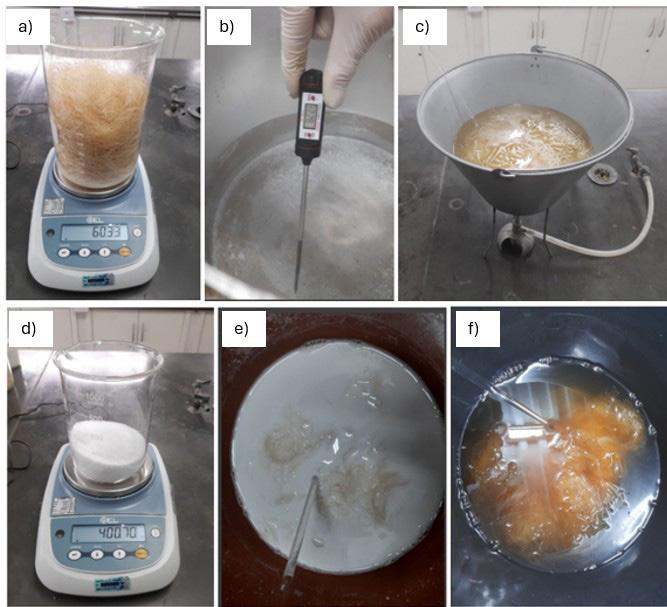
The production of the composites was carried out using biobased polyurethane (PU) resin and chemically treated sisal fibers as the main components. The process employed a 0.3 mm silicone release sheet, 3 mm acrylic plates, a circular cutter, a precision digital scale, and the resin system supplied by Kehl Ind. e Com. Ltda – ME.
After chemical treatment, the sisal fibers were manually cut to approximately 60 mm in length, following the methodology proposed by Angrizani et al.[18], with the aim of reducing void formation and improving fiber dispersion. A fiber content corresponding to 35 wt% relative to the mass of the polyurethane resin was used, with the PU mass kept constant. Thus, the fibers were added as reinforcement rather than as matrix replacement.
Molding was performed in an acrylic mold with dimensions of 90 × 265 × 3 mm, designed to ensure proper shaping, facilitate demolding, and standardize specimen dimensions (see Figure 2). The fibers were randomly arranged inside the mold. To limit uncontrolled expansion of the polyurethane, a blind acrylic plate was placed on top of the mold and a static load of approximately 29.7 kg (four concrete blocks) was applied for two hours. This procedure corresponds to a controlled expansion process with static pre-compaction, rather than conventional compression molding under defined pressure. After this step, the resin was poured, the composites were cured at room temperature for 4 h, and the specimens were subsequently demolded and cut according to ASTM D3039[19] and ASTM D635 standards.
The polyurethane system was formulated using a stoichiometric 1:1 mass ratio of components A (isocyanate) and B (polyol), as recommended in the product’s safety data sheet (FISPQ)[20]. An additional 15% was added to each
component to compensate for material losses due to adhesion and handling. Each component was stirred individually for 5 minutes and then mechanically mixed for an additional 5 minutes, following the manufacturer’s instructions. The mixing and resin preparation procedure is illustrated in the schematic diagram (see Figure 3).
The resulting PU mixture was poured directly onto the compacted fiber mat, allowing controlled expansion to ensure uniform impregnation of the reinforcement. The composite was then cured at room temperature for 4 hours. After curing, the specimens were demolded and cut according to the ASTM D3039[19] (tensile test) and ASTM D635 (horizontal flammability test) standards.
To evaluate the mechanical performance of the produced composites, tensile tests were performed in accordance with ASTM D3039. Specimens were manually cut from the molded composite panels, with standard dimensions of 250 mm in length, 25 mm in width, and 3 mm in thickness[8] A minimum of four specimens was tested for each material type: PU reinforced with NaOH-treated fibers, PU reinforced with Al(OH)3-treated fibers, and neat PU.
The tensile tests were conducted using an Emic universal testing machine equipped with a 100 kN load cell, operating at a constant crosshead speed of 2 mm·min−1[19] at room temperature.
Following mechanical testing, fracture surface analysis was carried out using a benchtop scanning electron microscope (SEM), model Hitachi TM 3000. The micrographs allowed for the identification of failure mechanisms such as fiber pull-out, matrix rupture, and fiber–matrix interfacial debonding, providing morphological evidence to support the mechanical test results.
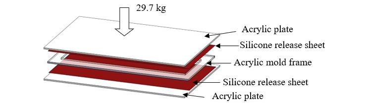
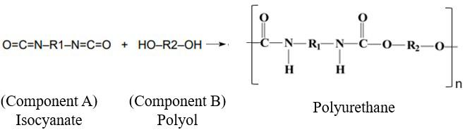
This section presents and discusses the main results from the mechanical and morphological characterization of biobased polyurethane composites reinforced with sisal fibers treated with alkaline solutions of NaOH and Al(OH)3. The tensile strength results of the composites are analyzed in comparison to neat PU, highlighting the specific contributions of each fiber treatment. Additionally, scanning electron microscopy (SEM) images of the fracture surfaces are examined to discuss the failure mechanisms observed, providing morphological insights that complement and help explain the mechanical behavior.
The tensile test results for neat polyurethane (PU) and for the composites reinforced with sisal fibers treated with alkaline solutions are presented in Table 1. The neat PU exhibited an average tensile strength of 6.46 ± 0.93 MPa, an elastic modulus of 0.08 ± 0.01 GPa, and an elongation at break of 8.12 ± 0.40%.
The incorporation of chemically treated sisal fibers significantly enhanced the mechanical performance of the PU matrix. The composite reinforced with NaOH-treated fibers achieved an average tensile strength of 14.09 ± 1.24 MPa, while the composite with Al(OH)3-treated fibers reached 15.14 ± 2.07 MPa, corresponding to increases of 118.11% and 134.36%, respectively, compared to neat PU.
Furthermore, the elastic modulus increased to 0.56 ± 0.04 GPa for the NaOH composite and to 0.75 ± 0.10 GPa for the Al(OH)3 composite. In contrast, the elongation at break decreased to 2.51 ± 0.11% and 2.02 ± 0.22%, respectively, indicating that the fiber reinforcement increased stiffness while reducing ductility.
One-way ANOVA was conducted to evaluate the differences among the three groups (neat PU and both fiberreinforced composites). The test yielded an F-value of 26.06 and a p-value of 0.000067, demonstrating a statistically significant difference among groups (p < 0.05). The F statistic represents the ratio of variance between groups to variance within groups, while the p-value corresponds to the probability, under the null hypothesis of equal means, of obtaining such an F-value. Post-hoc Tukey tests confirmed that both NaOH- and Al(OH)3-treated composites were significantly different from neat PU, with the Al(OH)3 treatment yielding the highest mean strength.
It is important to note that this study did not include a composite reinforced with untreated sisal fibers, due to the limited amount of resin available for processing. Therefore, while the present results demonstrate that fiber treatments are associated with improved mechanical performance compared to neat PU, further experiments
including untreated sisal as a control will be necessary to directly quantify the incremental effect of chemical modifications. Nevertheless, SEM analysis provides supporting evidence that the improvements observed are consistent with enhanced fiber–matrix interfacial bonding promoted by the treatments.
The revised stress–strain curves (see Figure 4) emphasize the mechanical advantages of the reinforced systems over neat PU. Both composites exhibit steeper initial slopes, indicating increased stiffness. After the peak stress, the curves show a sharp drop, characteristic of brittle fracture behavior with limited post-peak deformation. The composite reinforced with Al(OH)3-treated fibers displays the steepest initial slope, reflecting its superior elastic modulus. In contrast, the neat PU shows an extended region of nearly constant stress with increasing strain, which in some specimens was attributed to grip slippage artifacts; these curves were discarded and repeated to ensure reliable elongation-at-break data.
These results are in line with the findings of Sencadas et al.[21] , Kilinç et al.[16], and Liu et al.[17] , who reported increased tensile strength in composites reinforced with chemically treated sisal fibers. The values obtained in this study are consistent with those previously reported, considering the variability in fiber treatments and matrix structures.
The fracture morphology of the test specimens was analyzed by scanning electron microscopy (SEM) to better understand the failure mechanisms associated with the mechanical performance observed.
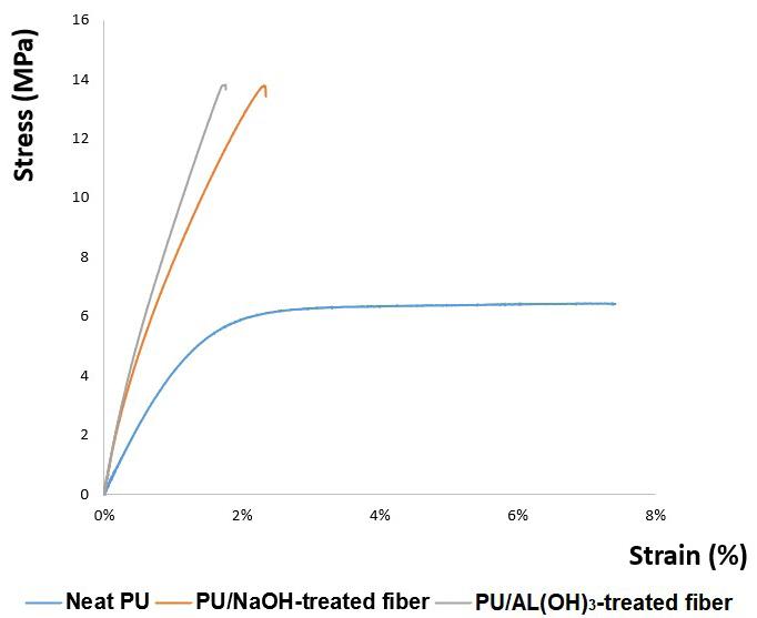
Mechanical performance of biobased polyurethane composites reinforced with treated sisal fibers
The SEM image of the fracture surface of neat polyurethane (PU) revealed a highly porous structure with numerous air bubbles and voids of varying sizes, distributed relatively homogeneously throughout the matrix (see Figure 5). While this morphology may reflect good uniformity during molding, it also suggests the presence of stress concentration zones that can negatively affect mechanical strength. The smooth edges of the pores and the presence of visible cracks support the hypothesis of brittle fracture behavior, consistent with findings reported in the literature[21].
The fracture surface of the composite reinforced with sisal fibers treated with NaOH reveals several distinct morphological features (see Figure 6). Voids are dispersed throughout the matrix, likely formed during the curing process due to the entrapment of volatile gases. These imperfections compromise the material’s homogeneity and may contribute to reduced tensile strength.
A reasonably homogeneous distribution of fibers with random orientations is also observed. While some fibers are well embedded in the matrix, others exhibit partial pull-out, indicating areas of weak interfacial adhesion. However, regions with visible residual matrix adhered to the fiber surfaces suggest localized mechanical interlocking, which may contribute positively to load transfer in certain zones.
This interpretation is further supported by the SEM analysis (see Figure 7), which highlights the occurrence of fiber pull-out, where fibers are partially extracted from the matrix during fracture. This behavior is typically associated with insufficient interfacial adhesion, potentially resulting from physical or chemical incompatibilities between the fiber and the matrix. At the same time, some fibers appear to have fractured rather than being pulled out (see Figure 7a), suggesting that effective stress transfer occurred from the matrix to the reinforcement. This combination of pull-out
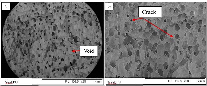
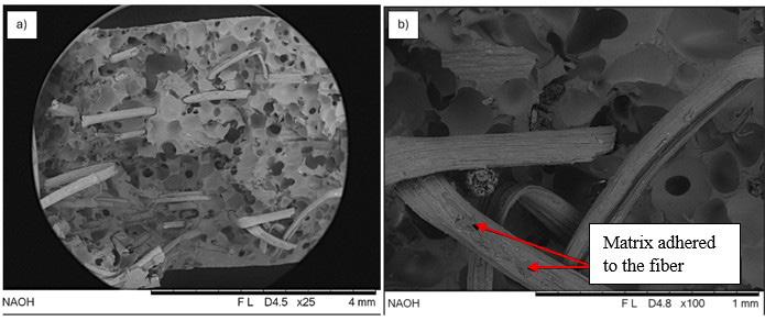
Oliveira, B. T., & Parreira, R. M.
and fiber fracture explains the higher tensile strength and stiffness of the Al(OH)3-treated composite, while its lower elongation at break indicates that these gains were accompanied by increased brittleness compared to the NaOH-treated system.
A transverse fracture of the NaOH-treated sisal fiber reveals important characteristics of the failure mechanism (see Figure 8). The fractured surfaces appear rough and inclined, with exposed microfibrillar layers, which are indicative of a shear-dominated failure. This morphology suggests that the fibers were able to absorb energy during loading and only fractured after reaching their tensile limit. Additionally, the presence of residual matrix adhered to the fiber surface reinforces the evidence of effective fiber–matrix interfacial bonding.
The fracture morphology of the composite reinforced with Al(OH)3-treated fibers reveals notable differences when compared to the NaOH-treated system (see Figure 9).
Fewer voids are observed throughout the matrix, suggesting greater homogeneity and more efficient stress transfer between the matrix and the fibers. Although the fiber pullout phenomenon is still present, it appears less pronounced, indicating improved interfacial bonding in certain regions. These microstructural features explain the higher tensile strength and stiffness of the Al(OH)3 composite; however, they are also consistent with its lower elongation at break, reflecting a more brittle behavior than the NaOH-treated system.
Additional morphological details of the Al(OH)3-treated fiber composite are presented (Figure 10). Partial separation of fiber bundles and the orderly detachment of layers are observed, indicating a shear-dominated failure mechanism. The progressive delamination of fiber layers suggests that the treatment preserved the hierarchical structure of the fibers, contributing to efficient load transfer and the higher stiffness observed. However, in agreement with the mechanical results, the overall composite exhibited lower elongation
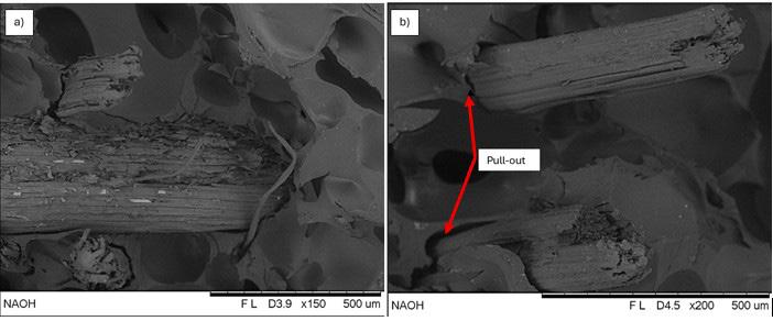
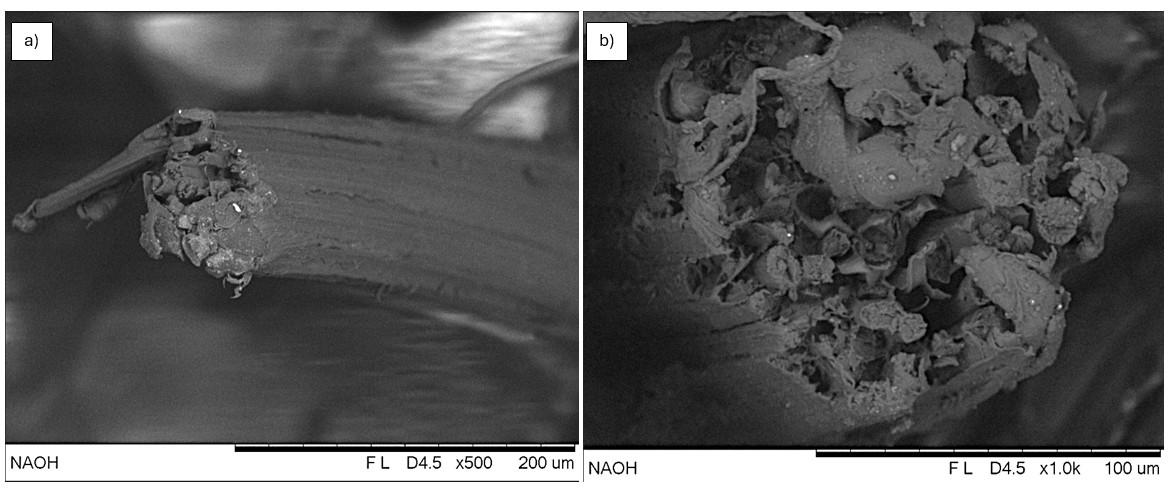
Mechanical performance of biobased polyurethane composites reinforced with treated sisal fibers
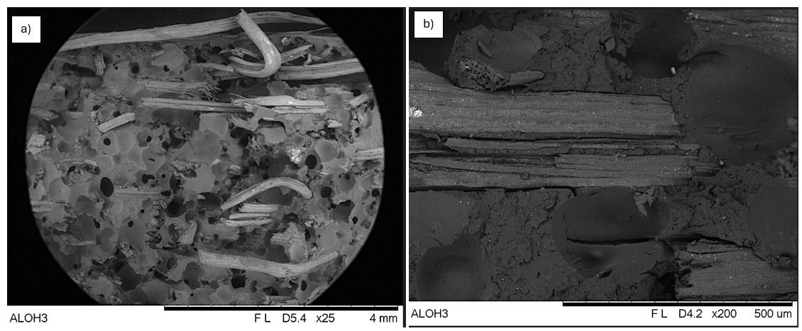
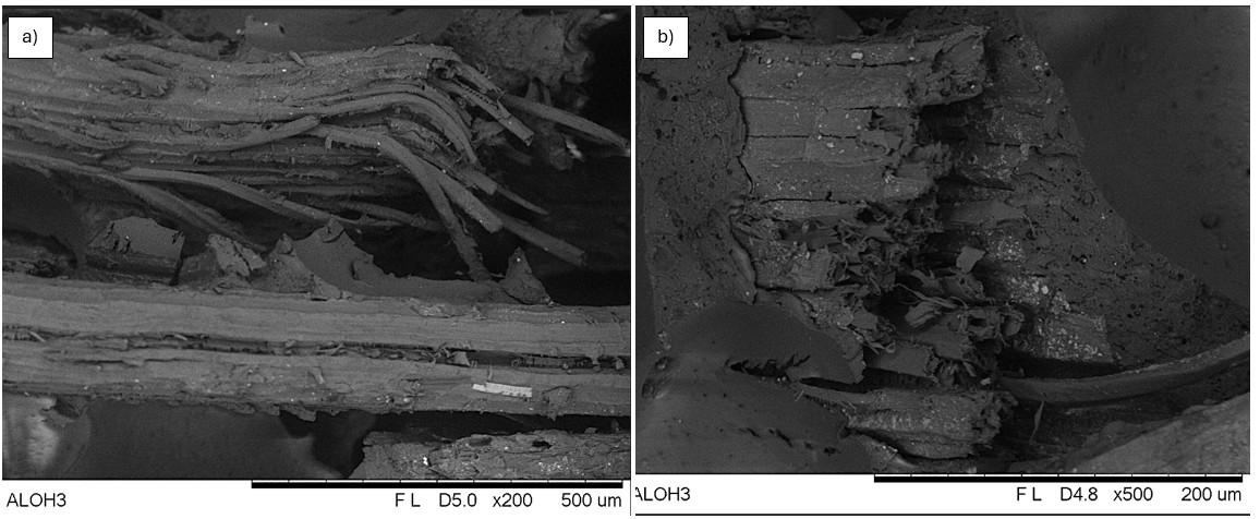
at break, reflecting a more brittle behavior compared to the NaOH-treated system. Furthermore, small bright regions (white spots) visible on the fiber surface may correspond to residual aluminum hydroxide particles. These residues could potentially enhance flame-retardant properties and improve fiber–matrix bonding by forming a protective layer or enhancing interfacial compatibility[16]
3.3 Correlation between morphology and mechanical performance
The correlation between the tensile properties and the fracture morphology reveals clear links between microstructure and performance. In neat PU, the low tensile strength (6.46 MPa) can be directly related to its highly porous structure, as evidenced in Figure 5. The presence of voids and entrapped air bubbles acted as stress concentrators, reducing
the effective cross-section of the material and favoring the premature nucleation of cracks. This microstructural condition limited the capacity for plastic deformation and promoted brittle fracture, which was also confirmed by the smooth pore edges and cracks observed under SEM, in agreement with previous studies[21]
When sisal fibers were incorporated, the mechanical performance improved substantially. The NaOH-treated composite reached 14.09 MPa, while the Al(OH)3-treated composite achieved 15.14 MPa, both significantly higher than neat PU. These results highlight the role of the fibers as effective reinforcements and show the importance of the fiber–matrix interface in governing stress transfer. The higher elastic modulus values measured for the composites confirm that the inclusion of fibers restricted matrix deformation, producing stiffer materials.
B. T., & Parreira, R. M.
The micrographs of the NaOH-reinforced composite (Figures 6-8) illustrate this effect. Although voids remained, reflecting imperfections from curing, the fibers appeared relatively well distributed in random orientations. Partial pull-out was observed in some regions, indicating areas of weaker adhesion, but several fibers retained residual matrix on their surfaces, suggesting localized interfacial bonding. This morphology explains the intermediate performance of this composite: tensile strength and modulus clearly superior to neat PU, while preserving slightly higher elongation at break compared with the Al(OH)3 composite.
The Al(OH)3-treated composite (Figures 9 and 10) displayed a distinct morphology, with fewer voids and more cohesive fiber–matrix integration. Shear-type fractures and fibrillar bundles suggested efficient load transfer and stronger interfacial bonding. Bright spots observed on fiber surfaces were attributed to aluminum hydroxide residues, which may contribute both to flame retardancy and to improved compatibility at the interface[10]. These structural features justify the highest tensile strength (15.14 MPa) and elastic modulus (0.75 GPa) obtained. However, the reduced elongation at break confirms that the Al(OH)3 composite was the most brittle system investigated, since the gains in stiffness were accompanied by a loss of deformability.
A direct comparison between the two treatments reveals a trade-off between strength, stiffness, and ductility. The NaOH-treated composite provided significant reinforcement and maintained a limited capacity for deformation, while the Al(OH)3 treatment maximized stiffness and strength but produced the most brittle response. These differences reflect the distinct chemical effects of the treatments: NaOH removed amorphous constituents such as hemicellulose and lignin, increasing fiber roughness and promoting mechanical interlocking, while Al(OH)3 generated surface deposits that enhanced load transfer but also reduced fiber flexibility, limiting the ability of the composite to accommodate strain.
Taken together, these results confirm that porosity, fiber–matrix adhesion, and fracture mechanisms are decisive factors in the mechanical behavior of PU–sisal composites. Both chemical treatments improved reinforcement significantly, but with different balances: Al(OH)3 produced the stiffest and strongest composite, albeit the most brittle, while NaOH offered a more balanced compromise between stiffness and residual ductility. These findings emphasize that fiber treatments must be tailored to the intended application, depending on whether stiffness, strength, or toughness is the primary requirement.
This study aimed to evaluate the mechanical and morphological behavior of sustainable composites based on biobased polyurethane reinforced with sisal fibers treated with alkaline solutions of NaOH and Al(OH)3. Based on the results obtained, the proposed objective was successfully achieved.
The incorporation of chemically treated fibers led to a significant enhancement in the mechanical performance of the composites, confirming the effectiveness of sisal fiber reinforcement in biopolymer matrices. The tensile strength, stiffness, and modulus values increased considerably in both
reinforced systems when compared to neat polyurethane. Furthermore, the SEM-based morphological evaluation provided valuable insights into the fracture mechanisms, emphasizing the crucial role of fiber–matrix interfacial bonding.
The composite reinforced with Al(OH)3-treated fibers exhibited better interfacial integration and a more uniform internal structure, resulting in the highest stiffness and tensile strength. However, these gains were accompanied by the lowest elongation at break, confirming its more brittle behavior. In contrast, the NaOH-treated composite also provided significant improvements over neat PU but retained slightly greater ductility, representing a more balanced compromise between stiffness and deformability.
Overall, the findings reinforce the viability of using chemically modified natural fibers as reinforcements in sustainable composite systems. The mechanical improvements, combined with the environmental advantages of biobased materials, support the application of these composites in engineering contexts that demand low weight, renewable sourcing, and reliable mechanical performance.
• Conceptualization – Bruno Targino de Oliveira; Renata Martins Parreira.
• Data curation – Bruno Targino de Oliveira; Renata Martins Parreira.
• Formal analysis – Bruno Targino de Oliveira.
• Funding acquisition – NA.
• Investigation – Bruno Targino de Oliveira; Renata Martins Parreira.
• Methodology – Bruno Targino de Oliveira; Renata Martins Parreira.
• Project administration – Bruno Targino de Oliveira; Renata Martins Parreira.
• Resources – Bruno Targino de Oliveira.
• Software – NA.
• Supervision – NA.
• Validation – Bruno Targino de Oliveira; Renata Martins Parreira.
• Visualization – Bruno Targino de Oliveira; Renata Martins Parreira.
• Writing – original draft – Bruno Targino de Oliveira.
• Writing – review & editing – Bruno Targino de Oliveira; Renata Martins Parreira.
The authors would like to express their gratitude to Centro Universitário de Volta Redonda (UniFOA) for providing the chemical reagents used in the fiber surface treatments and for granting access to the laboratory facilities required for the characterization experiments. They also thank Kehl Indústria e Comércio Ltda – ME for the technical support and for supplying the polyurethane resin system used in this study.
Mechanical performance of biobased polyurethane composites reinforced with treated sisal fibers
1 Mora-Murillo, L. D., Orozco-Gutiérrez, F., Vega-Baudrit, J., & González-Paz, R. J. (2017). Thermal-mechanical characterization of polyurethane rigid foams: effect of modifying bio-polyol content in isocyanate prepolymers. Journal of Renewable Materials, 5(3-4), 220-230 https://doi.org/10.7569/JRM.2017.634112
2 Ionescu, M. (2005). Chemistry and technology of polyols for polyurethanes. Shawbury: Rapra Technology Limited.
3 Faruk, O., Bledzki, A. K., Fink, H.-P., & Sain, M. (2012). Biocomposites reinforced with natural fibers: 2000–2010. Progress in Polymer Science, 37(11), 1552-1596 https://doi. org/10.1016/j.progpolymsci.2012.04.003
4 Yan, L., Chouw, N., & Jayaraman, K. (2014). Flax fibre and its composites – A review. Composites. Part B, Engineering, 56, 296-317. https://doi.org/10.1016/j.compositesb.2013.08.014.
5 Rev, T., Wisnom, M. R., Xu, X., & Czél, G. (2022). The effect of transverse compressive stresses on tensile failure of carbon fibre/epoxy composites. Composites. Part A, Applied Science and Manufacturing, 156, 106894. https://doi.org/10.1016/j. compositesa.2022.106894
6 Monteiro, S. N., Lopes, F. P. D., Barbosa, A. P., Bevitori, A. B., Silva, I. L. A., & Costa, L. L. (2011). Natural lignocellulosic fibers as engineering materials: an overview. Metallurgical and Materials Transactions. A, Physical Metallurgy and Materials Science, 42(10), 2963-2974 https://doi.org/10.1007/s11661011-0789-6
7 Liao, Z., Hu, Y., Shen, Y., Chen, K., Qiu, C., Yang, J., & Yang, L. (2024). Investigation into the reinforcement modification of natural plant fibers and the sustainable development of thermoplastic natural plant fiber composites. Polymers, 16(24), 3568 https://doi.org/10.3390/polym16243568 PMid:39771421.
8 Fernandes, R. A. P., Silveira, P. H. P. M., Bastos, B. C., Pereira, P. S. C., Melo, V. A., Monteiro, S. N., Tapanes, N. L. C. O., & Bastos, D. C. (2022). Bio-based composites for light automotive parts: statistical analysis of mechanical properties; effect of matrix and alkali treatment in sisal fibers. Polymers, 14(17), 3566 https://doi.org/10.3390/polym14173566 PMid:36080641.
9. Campos, A., Teodoro, K. B. R., Marconcini, J. M., Mattoso, L. H. C., & Martins-Franchetti, S. M. (2011). Effect of fiber treatments on properties of thermoplastic starch/polycaprolactone/ sisal biocomposites. Polímeros: Ciência e Tecnologia, 21(3), 217-222. https://doi.org/10.1590/S0104-14282011005000039.
10 Ichim, M., Muresan, E. I., & Codau, E. (2024). Natural-fiberreinforced polymer composites for furniture applications: technical, ecological and economic demands. Polymers, 16(22), 3113. https://doi.org/10.3390/polym16223113. PMid:39599204.
11 Thimmegowda, D. Y., Hindi, J., Markunti, G. B., & Kakunje, M. (2025). Enhancement of mechanical properties of natural fiber reinforced polymer composites using different approaches: a review. Journal of Composites Science, 9(5), 220 https:// doi.org/10.3390/jcs9050220
12 Thepruttana, S., Patthanavarit, J., Hankoy, M., Kitiwan, M., Keawprak, N., & Tunthawiroon, P. (2024). Enhancement
of flexural strength in fiber–cement composites through modification of sisal fiber with natural rubber latex and expanded perlite. Buildings (Basel, Switzerland), 14(4), 1067 https://doi.org/10.3390/buildings14041067
13. Merlini, C., Soldi, V., & Barra, G. M. O. (2011). Influence of fiber surface treatment and length on physico-chemical properties of short random banana fiber-reinforced castor oil polyurethane composites. Polymer Testing, 30(8), 833-840 https://doi.org/10.1016/j.polymertesting.2011.08.008
14. Olanrewaju, O., Oladele, I. O., & Adelani, S. O. (2025). Recent advances in natural fiber reinforced metal/ceramic/ polymer composites: an overview of the structure-property relationship for engineering applications. Hybrid Advances, 8, 100378 https://doi.org/10.1016/j.hybadv.2025.100378
15 Islam, S., Hasan, B., Kodrić, M., Motaleb, K. Z. M. A., Karim, F.-E., & Islam, R. (2025). Mechanical properties of hemp fiber-reinforced thermoset and thermoplastic polymer composites: a comprehensive review. SPE Polymers, 6(1), e10173 https://doi.org/10.1002/pls2.10173
16 Kılınç, A. C., Atagür, M., Özdemir, O., Şen, I., Küçükdoğan, N., Sever, K., Seydibeyoğlu, O., Sarikanat, M., & Seki, Y. (2016). Manufacturing and characterization of vine stem reinforced high density polyethylene composites. Composites. Part B, Engineering, 91, 267-274 https://doi.org/10.1016/j. compositesb.2016.01.033
17. Liu, Y., Zhang, X., Liu, J., Xing, D., Shen, H., Chen, D., & Sun, J. (2015). Superelasticity in polycrystalline Ni-Mn-Ga-Fe microwires fabricated by melt-extraction. Materials Research, 18(Suppl. 1), 61-65. https://doi.org/10.1590/1516-1439.325914.
18 Angrizani, C. C., Amico, S. C., Cioffi, M. O. H., & Zattera, A. J. (2014). Influência da espessura nas propriedades mecânicas de compósitos híbridos interlaminares de curauá/vidro/ poliéster. Polímeros, 24(2), 184-189 https://doi.org/10.4322/ polimeros.2014.063
19 American Society for Testing and Materials - ASTM. (2017). ASTM D3039/D3039M-17: Standard test method for tensile properties of polymer matrix composite materials. West Conshohocken: ASTM. Retrieved in 2025, July 15, from https://www.astm.org/d3039_d3039m-17.html
20 Kehl Indústria e Comércio Ltda – ME. (2022). FISPQ – Ficha de Informações de Segurança de Produto Químico: Sistema Poliol + Isocianato PU Vegetal. Retrieved in 2025, July 15, from https://www.kehl.ind.br
21 Sencadas, V., Correia, D. M., Ribeiro, C., Moreira, S., Botelho, G., Gómez Ribelles, J. L., & Lanceros-Méndez, S. (2012). Physical–chemical properties of cross-linked chitosan electrospun fiber mats. Polymer Testing, 31(8), 1062-1069 https://doi.org/10.1016/j.polymertesting.2012.07.010
Received: Jul. 15, 2025
Revised: Oct. 05, 2025
Accepted: Nov. 04, 2025
Editor-in-Chief: Sebastião V. Canevarolo
Shih-Hang Chang1* and Chun-Yi Tseng1
1Department of Chemical and Materials Engineering, National I-Lan University, I-Lan, Taiwan
*shchang@niu.edu.tw
Obstract
This study investigates the surface modification of gelatin films coated on stainless steel using radio-frequency plasma treatment, with a particular emphasis on O2-plasma. Gelatin films cross-linked with glutaraldehyde were subjected to radio frequency plasma modification using N2, O2, and Ar atmospheres. Results showed that O2-plasma was most effective, reducing the water contact angle from 97.3° to 24.9° after 600 seconds due to the introduction of hydrophilic functional groups (–OH, –COOH, –CONH2). Short O2-plasma treatments (10-30 s) significantly decreased bovine serum albumin (BSA) adsorption from 452.5 to 334.4 μg/L (P < 10−4), indicating improved anti-protein adsorption behavior. However, treatments exceeding 60 seconds caused surface cracking and increased BSA adsorption due to higher roughness. The study concludes that controlled short-term O2-plasma modification effectively enhances the surface performance of gelatin-coated stainless steel for biomedical applications.
Keywords: gelatin, plasma, surface modification, bovine serum albumin.
Data Availability: All data supporting the findings of this study are available from the corresponding author upon request.
How to cite: Chang, S.-H., & Tseng, C.-Y. (2026). Surface properties of stainless steel coated with plasma-modified gelatin films. Polímeros: Ciência e Tecnologia, 36(1), e20260005. https://doi.org/10.1590/0104-1428.20250067
For decades, metallic biomaterials such as stainless steel, titanium and titanium alloys, cobalt-based alloys, and TiNi shape memory alloys have been extensively utilized in surgical prosthetics and orthotics[1-3]. These materials are generally characterized by their excellent mechanical properties and adequate biocompatibility, making them suitable for various medical and surgical applications. Stainless steel is commonly employed for orthopedic implants, such as in joint replacement and bone fracture fixation, mainly due to its low cost[4-6]. A key drawback, however, is the corrosion that occurs upon interaction with living tissues. This process compromises the protective chromium oxide layer, leading to the release of metallic ions (Ni2+, Cr3+, and Fe3+) into the body. These released ions are potential hazards that can cause local and systemic adverse effects, contribute to prosthetic loosening, and interfere with the essential proliferation and differentiation balance observed in osteoblastic human alveolar bone cell cultures. Therefore, a significant challenge when these metallic biomaterials are exposed to physiological environments is their inherent inadequate corrosion resistance and the potential for undesirable leaching of metallic ions, which may restrict their long-term clinical viability. To overcome these limitations, the surfaces of these biomaterials are routinely modified or protected by various biomedical coatings, including ceramics, bioactive glass, functional coatings, and various polymers[7-15]. Gelatin is a highly versatile biomaterial, and it is frequently applied in coatings across diverse fields, notably within biomedicine.
Its biocompatibility, biodegradability, and unique capacity to mimic the extracellular matrix render it exceptionally wellsuited for tissue engineering and drug delivery. Therefore, gelatin is also a potential candidate for surface protection materials for metallic implants.
A substantial body of research has consistently demonstrated the significant potential of gelatin and its composite derivatives for various biomedical applications[16-18]. For instance, Tytgat et al.[19] developed a novel norbornene-functionalized gelatin combined with thiolated gelatin to create hydrogel scaffolds via additive manufacturing for adipose tissue engineering. These photo-click scaffolds, incorporating a cell-interactive crosslinker, formed a homogeneous network through step-growth polymerization. Benchmarked against methacrylamide-modified gelatin, these scaffolds exhibited superior physicochemical properties, supported high cell viability and proliferation, and demonstrated enhanced adipogenic differentiation, thus proving promising for tissue reconstruction. Ghorbani et al.[20] developed polycaprolactone (PCL) scaffolds, which were freeze-cast and subjected to oxygen plasma modification to facilitate gelatin grafting. This surface modification significantly enhanced the scaffolds’ hydrophilicity and biodegradation while improving cell attachment and viability. The modified scaffolds also effectively supported filopodia formation. These findings collectively suggest that gelatin-grafted, oxygen plasma-modified PCL scaffolds hold considerable promise for wound healing applications. Wattanavijitkul et al.[21] fabricated poly(vinyl
Chang, S.-H., & Tseng, C.-Y.
alcohol)/gelatin (PVA/gelatin) hydrogel films, cross-linked with glutaraldehyde, to coat vancomycin-loaded titania nanotubes (TNTs). This aimed to enhance biocompatibility and achieve controlled vancomycin release. The coated TNTs demonstrated slower vancomycin release compared to uncoated TNTs. Furthermore, they promoted osteogenesis, evidenced by increased alkaline phosphatase activity and calcium accumulation, and exhibited antimicrobial efficacy against E. coli and S. aureus. These findings highlight the potential for efficient drug delivery and controlled release in biomedical implant applications.
Gelatin’s surface is frequently modified for medical applications to overcome its inherent limitations and tailor its properties for specific biomedical functions. Common surface modification techniques include grafting, chemical crosslinking, nanoparticle coatings, and plasma modification[22-24] . Among these, plasma surface modification stands out as an economical and effective method for enhancing biomaterial films’ biocompatibility, biofunctionality, and hydrophilicity[25-29]
Plasma is recognized as the fourth state of matter, formed by energizing a gas. This energy input causes excitation and subsequent partial or complete ionization of the gas molecules. The resulting plasma is a complex mix of ions, free radicals, reactive species, unstable dynamic molecules, and radiation of varying wavelengths emitted as excited molecules stabilize. Consequently, plasma processes have become a promising alternative to conventional coating and grafting methods for the surface modification of polymeric membrane materials, offering significant advantages such as fast reaction times, waste-free operation, and high versatility[30]. Several studies report that plasma modifications effectively enhance the surface properties of gelatin for biomedical applications. For example, Mozaffari et al.[31] introduced novel argon and argon–oxygen plasma treatments for electrospun tannic acid-crosslinked gelatin nanofibers, specifically targeting tissue engineering applications. Their research indicated that plasma treatment increased surface roughness and introduced new chemical groups on the nanofibers. Notably, argon–oxygen plasma significantly enhanced hydrophilicity, which fostered greater fibroblast cell adhesion and viability. Hesari et al.[32] fabricated porous polyurethane (TPU) scaffolds using freeze-drying and subsequently grafted gelatin onto them via oxygen plasma treatment. This modification significantly enhanced the scaffolds’ wettability and hydrolytic biodegradation. Although a slight decrease in mechanical properties was observed, the authors suggested that this method successfully created an activated surface for gelatin grafting, thereby achieving optimal features for neo-tissue formation. Despite these advancements in modifying gelatin on other substrates, the effects of plasma modifications directly on gelatin films’ intrinsic properties remain largely unexplored. Therefore, this study aims to investigate how plasma surface modification influences the surface properties of gelatin films.
2.1 Preparation and surface modification of gelatin films
The stainless steel used in this study was acquired from Soonglee Metals Inc., Taiwan. Its surface underwent progressive grinding with abrasive paper, followed by polishing
with 0.3 µm Al2O3 powder. The stainless steel specimens were then precisely cut into dimensions of 20 × 30 × 1 mm using a low-speed diamond saw. To ensure cleanliness, the stainless steel samples were sequentially cleaned with isopropanol and deionized water to remove any residual organic matter. Subsequently, these cleaned samples were immersed in piranha solution (a 3:1 v/v mixture of concentrated sulfuric acid (95%) and hydrogen peroxide solution (35%)) for 15 minutes. This pretreatment aimed to increase the density of hydroxyl functional groups on the sample surface. The gelatin solution was prepared by thoroughly mixing 0.5 g of gelatin and 25 mL of 85% formic acid. This mixture was stirred at 300 rpm at room temperature until the gelatin was completely dissolved. Following dissolution, 0.5 mL of 25% glutaraldehyde was added as a cross-linking agent. The solution was allowed to react for 30 minutes, then left to stand to remove any air bubbles. For coating, the pretreated stainless steel specimens were placed in a glass culture dish, and the prepared gelatin solution was poured over them. The dishes were then placed in a vacuum cabinet at room temperature for 24 hours to facilitate the formation of the gelatin-coated stainless steel specimens, which were subsequently used for characterization. All chemical reagents, including gelatin, formic acid, and glutaraldehyde, were purchased from Echo Chemical Co. Ltd., Taiwan.
Some of the gelatin-coated stainless steel specimens underwent further surface modification via plasma treatment. The plasma modification was carried out using a radio frequency (RF) plasma system, which consisted of a Pyrex bell jar reactor. The RF generator’s frequency was set to 13.56 MHz. Within the reactor, the cathode was connected to the high-potential end of the RF generator, while the anode was grounded. The gelatin-coated specimens were positioned on the anode electrode. The distance between the cathode and anode was maintained at 100 mm. Before gas introduction, the system was evacuated to a base pressure of 10−3 Torr or below. High-purity gases (99.9%) of argon, oxygen, and nitrogen were then separately introduced into the chamber as working gases. The working pressure was adjusted to a stable 0.125 Torr with a flow rate of 10 sccm for each gas. The plasma modification process itself was performed at a constant power of 50 W, with treatment durations varying from 10 to 600 sec.
The wettability properties of the plasma-modified gelatin film surfaces were assessed using the sessile drop method with a contact angle instrument (FTA125, First Ten Ångstroms, USA). The measuring range of the water contact angle meter is 0° to 180°, the experimental accuracy is 0.01°, and the minimum scale for quantitative titration is 0.002 mL. Nine measurements were recorded at various locations on the film; the maximum and minimum values were omitted to calculate the average contact angle. The functional groups present on the plasma-modified gelatin films were identified using an attenuated total reflectance Fourier-transform infrared (ATRFTIR) spectrometer (Spectrum 100, PerkinElmer). The spectral range of the ATR-FTIR spectrometer is 7,800 to 350 cm-1, the wavelength resolution is 0.5 cm-1, and the wavelength accuracy is 0.1 cm-1. Each specimen was measured in the range of 4000–6500 cm-1 using 16 scans at a resolution of 4 cm-1. Surface
Surface properties of stainless steel coated with plasma-modified gelatin films
morphology observations of the plasma-modified gelatin films were performed using a scanning electron microscope (SEM) (5136 MM, Tescan Instruments). The amount of adsorbed protein on the surface of plasma-modified gelatin films was quantified using the bicinchoninic acid (BCA) protein assay. Bovine serum albumin (BSA), purchased from Bio Basic Inc., served as the protein for the BCA assay. Phosphate buffer solution (PBS) and sodium dodecyl sulfate (SDS), used for protein adsorption analysis, were acquired from UniRegion and Sigma-Aldrich, respectively. The optical density (OD) values from the protein adsorption analysis were measured at 562 nm using a spectrophotometer (GENESYS 20, Thermo Scientific), with PBS solution as the blank cuvette. The spectral bandwidth of the spectrometer is less than 8 nm, the wavelength accuracy is 2 nm. The average OD value was calculated based on nine measurements, omitting the maximum and minimum values.
3.1 Wettability properties
Figure 1 presents the water contact angles (WCAs) of stainless steel, stainless steel coated with unmodified gelatin film, and those coated with plasma-modified gelatin films using N2, O2, and Ar atmospheres for 600 sec. The bare stainless steel and the unmodified gelatin-coated samples exhibited hydrophobic surfaces, with WCAs of approximately 94.3 ± 1.9° and 97.3 ± 2.3°, respectively. While gelatin is generally considered hydrophilic due to its abundance of carboxyl, amino, hydroxyl, and amide functional groups, the hydrophobic nature of the unmodified gelatin film observed in this study is attributed to the inclusion of glutaraldehyde during the cross-linking process, which alters the film’s surface hydrophilicity. Plasma modification significantly reduced the WCA of the gelatin surface from above 90° to approximately 34.7 ± 1.7° (N2-plasma), 24.9 ± 2.5° (O2-plasma), and 45.2 ± 1.0° (Ar-plasma) after 600 sec of treatment. This indicates that plasma modification with all tested atmospheres rendered the gelatin surface hydrophilic. Notably, O2-plasma modification demonstrated a more pronounced effect than N2 or Ar because of its relatively higher reactivity. Consequently, subsequent experiments will focus exclusively on the impact of O2-plasma modification on the surface properties of the gelatin films.
Figure 2 illustrates the WCAs of unmodified and O2-plasma modified gelatin films treated for various time intervals. The WCA of the gelatin film significantly decreased from approximately 97.3 ± 2.3° to 47.2 ± 2.8° after only 10 sec of O2-plasma modification. This notable reduction demonstrates that even a short-term O2-plasma treatment can effectively enhance the hydrophilicity of the gelatin film surface. Subsequently, the WCA gradually decreased with increasing O2-plasma modification time, reaching a minimum of 24.9 ± 2.5° after 600 sec treatment.
Figure 3 presents the ATR-FTIR spectra of stainless steel specimens coated with O2-plasma modified gelatin films treated for various time intervals. As shown in Figure 3, the unmodified gelatin film exhibits characteristic absorption bands. A broad peak observed between approximately
3000–3500 cm−1 is attributed to the overlapping stretching vibrations of the –NH and –OH groups. The band at approximately 2942 cm−1 corresponds to the stretching vibration of the –CH group. Furthermore, the characteristic absorption band at 1631 cm−1 is assigned to the C=O stretching of the primary amide (Amide I), while the band at 1538 cm−1 corresponds to the –NH bending vibration and –NO and –CN stretching of the secondary amide (Amide II). The peak at approximately 1450 cm−1 is indicative of the –C=N stretching of the aldimine formed due to gelatin cross-linking. Finally, the absorption band at approximately 1080 cm−1 is assigned to the –CO stretching vibration.
Figure 3 further illustrates that the characteristic peaks corresponding to oxygen-containing and nitrogen-containing functional groups became more pronounced following O2-plasma modification. This enhancement is attributed to the reaction between active plasma species and atoms on the gelatin film surface, leading to new oxygen-containing functional groups forming during modification. Additionally, free radicals generated on the gelatin surface during plasma treatment may react with atmospheric nitrogen, forming various nitrogen-containing functional groups. Consequently,
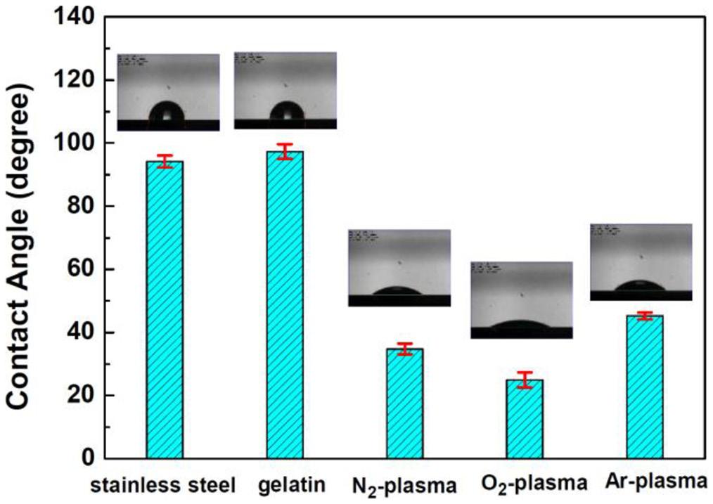
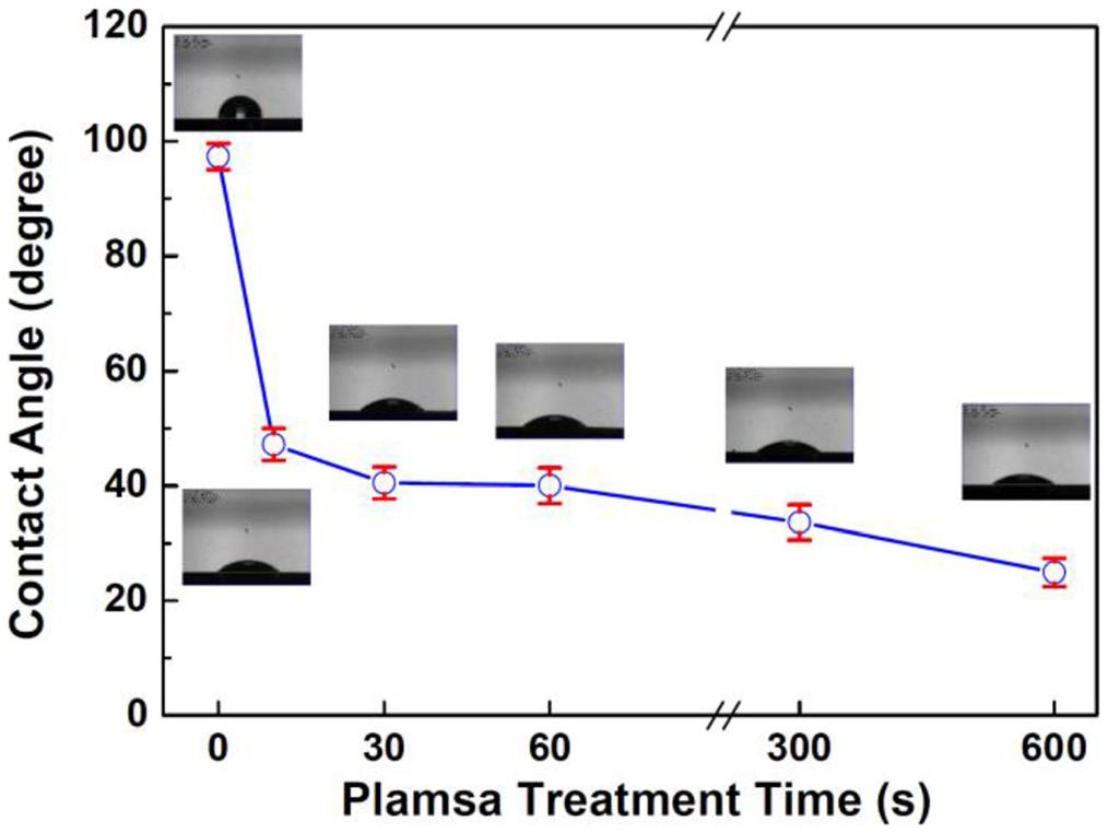
the observed increase in hydrophilic functional groups such as –OH, –COOH, and –CONH2 is directly responsible for the improved hydrophilicity of the gelatin film surface after plasma modification
Figures 4a-f present SEM images (100× magnification) showing the surface morphology of gelatin films modified by O2-plasma for 0 (unmodified), 10, 30, 60, 300, and 600 sec, respectively. Figure 4a shows that the unmodified
gelatin film exhibits a smooth and homogeneous surface morphology. Figures 4b-d reveal that this smooth and homogeneous surface remains intact when the O2-plasma modification duration is less than 60 sec. However, Figure 4e depicts the initial appearance of fine cracks on the gelatin surface after 300 sec O2-plasma modification, as indicated by the arrows. With extended treatment to 600 sec, Figure 4f clearly shows more pronounced crack propagation (indicated by arrows). This observation suggests that prolonged O2plasma modification time leads to the deterioration of the surface integrity of the gelatin films.
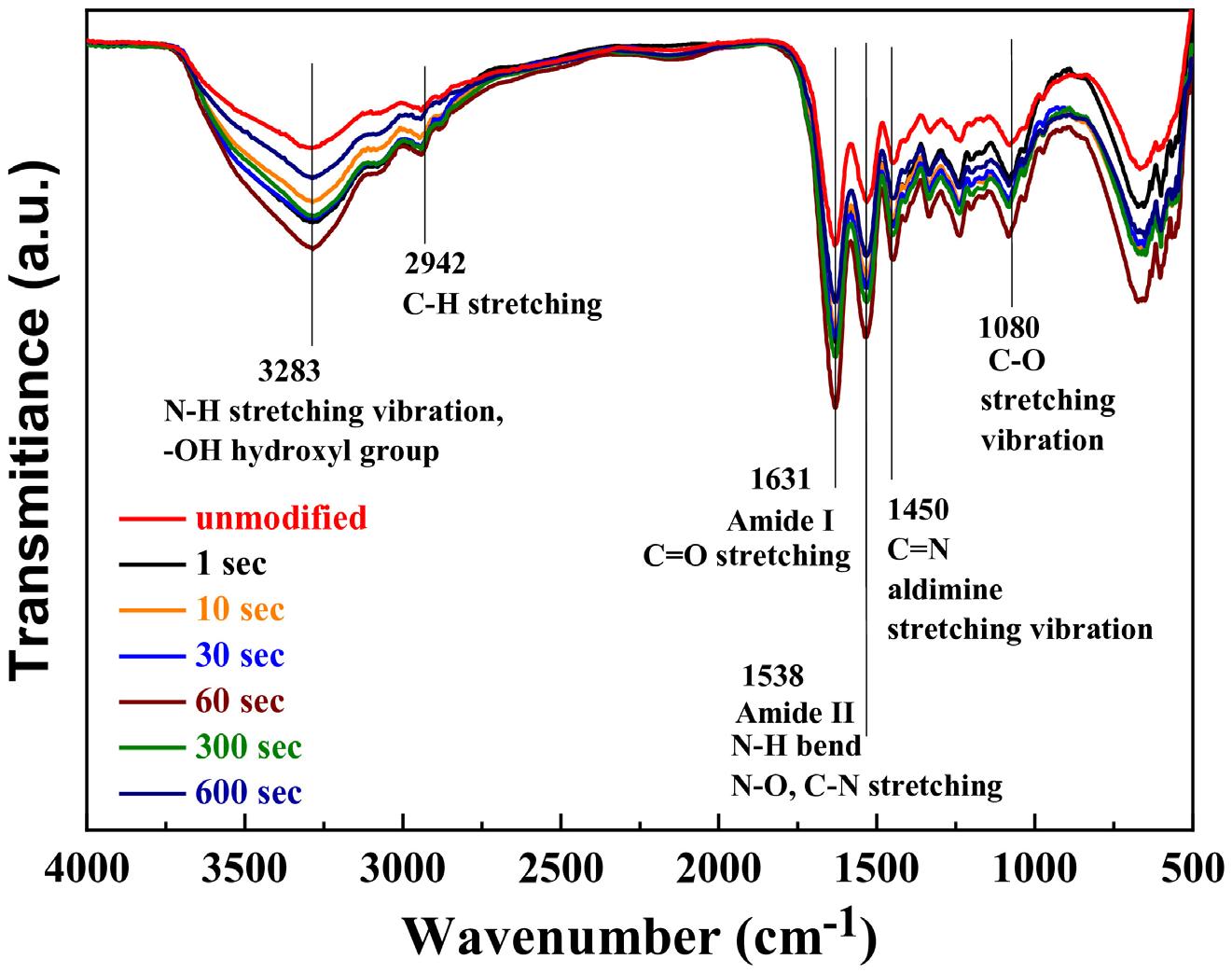
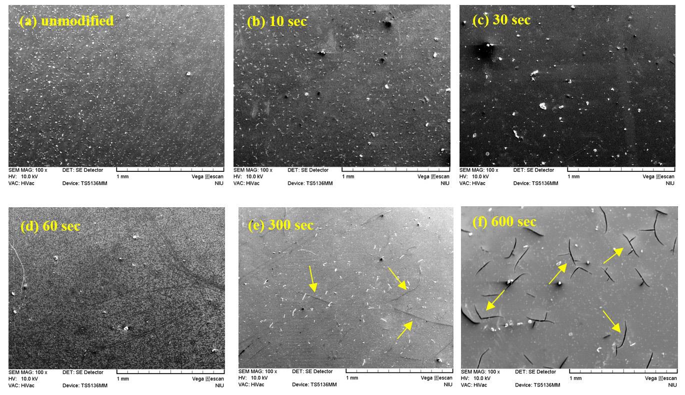
Surface properties of stainless steel coated with plasma-modified gelatin films
The protein adsorption properties of O2-plasma modified gelatin films were determined using a BCA protein assay. All unmodified and O2-plasma modified gelatin films were first rinsed with PBS three times. Each rinsed film was immersed in 5 mL of BSA solution at 37 °C for 24 hours, followed by another rinse with PBS. Subsequently, each film was incubated in 2 mL of SDS solution for 24 hours to desorb the adsorbed protein. A 0.1 mL aliquot from each resulting solution was mixed with 1 mL of BCA solution in a cuvette, and its OD was measured using a spectrophotometer. The concentration of BSA adsorbed onto the films was calculated from these OD values using a pre-established BSA concentration standard curve.
Figure 5 presents the concentrations of adsorbed BSA on the surfaces of the unmodified and O2-plasma modified gelatin films in the BCA protein assay. The unmodified gelatin film exhibited a BSA adsorption concentration of approximately 452.5 ± 22.8 µg/L. Notably, after just 10 sec of O2-plasma modification, the BSA concentration on the gelatin film’s surface significantly decreased to 394.8 ± 19.5 µg/L. This marked reduction indicates plasma modification effectively enhances the film’s anticoagulant properties. Further increasing the O2-plasma modification time initially led to a continued decrease in adsorbed BSA, reaching approximately 334.4 ± 19.0 µg/L after 30 sec of O2-plasma modification. However, for O2-plasma modification times extending from 60 to 600 s, the concentration of adhered BSA on the surface of the modified gelatin films showed a slight increase, rising from 421.0 ± 36.4 to 442.2 ± 24.5 µg/L.
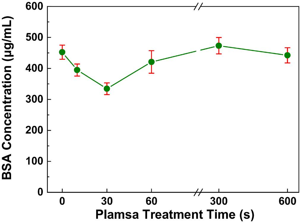
Figure 5. BSA adsorption concentrations of stainless steel specimens coated with O2-plasma modified gelatin films as a function of plasma treatment duration.
Table 1 lists the 95% confidence interval values and the P-values of the BSA adsorption concentrations of stainless steel specimens coated with O2-plasma modified gelatin films estimated from Figure 5. According to the significance analysis, the P-values calculated from the BSA adhesion concentration results were approximately 2.9 × 10⁻⁴ and 1.5 × 10⁻⁶ after O2-plasma modification for 10 and 30 sec, respectively. This indicates that the decrease in the BSA adhesion concentration upon 10 and 30 sec O2-plasma modifications was highly significant (P≪0.05). Accordingly, we concluded that both 10 and 30 sec O2-plasma modification effectively improved the protein adsorption property of the gelatin film. On the other hand, the P-values calculated from the BSA adhesion concentration results were approximately 0.0808, 0.1420, and 0.4314 after O2-plasma modification for 60, 300, and 600 sec, respectively. This suggests no statistically significant difference between the unmodified gelatin film and the prolonged O2-plasma modified gelatin films.
Figure 5 and Table 1 illustrate that short-term O2-plasma modification significantly reduces the quantity of BSA protein adsorbed on the gelatin film surface. This phenomenon can be attributed primarily to the enhanced hydrophilicity of the gelatin film surface after plasma treatment. Proteins typically exhibit a higher affinity for hydrophobic surfaces, as nonpolar environments can destabilize proteins. This promotes conformational reorientations, leading to stronger proteinprotein and protein-surface interactions[33 34]. Additionally, BSA is rich in carboxylic acid groups, and the abundant carboxylic acid groups introduced on the plasma-modified gelatin surface may generate charge-charge repulsion, further inhibiting BSA adhesion. However, an unexpected trend was observed for prolonged plasma treatment: gelatin films modified for more than 60 sec exhibited a higher concentration of adsorbed BSA than films treated for 30 sec, despite their superior hydrophilicity. This counterintuitive result stems from the formation of cracks on the film surface after prolonged O2-plasma modification, as demonstrated in Figure 4. These surface cracks increase the surface roughness, leading to a higher concentration of BSA protein adsorption. Therefore, this study demonstrates that while O2-plasma modification significantly improves the hydrophilicity and reduces protein adsorption of gelatin, whereas precise control over the plasma treatment duration is crucial to avoid surface deterioration.
This study demonstrated the potential of O2-plasma modified gelatin films for various biomedical applications, particularly when coated on stainless steel. A central finding
Table 1. The 95% confidence interval values and the P-values of the BSA adsorption concentrations of stainless steel specimens coated with O2-plasma modified gelatin films estimated from Figure 5.
O2-plasma modifications
Chang, S.-H., & Tseng, C.-Y.
was the successful conversion of initially hydrophobic gelatin films into hydrophilic surfaces through O2-plasma modification. This enhanced hydrophilicity, characterized by a substantial reduction in water contact angles, was attributed to the increased presence of hydrophilic functional groups such as –OH, –COOH, and –CONH2 on the film surface. Short-term O2-plasma treatments (10-30 sec) effectively inhibited BSA adsorption on the gelatin films. This beneficial effect is primarily linked to the improved hydrophilicity, as proteins generally exhibit lower affinity for hydrophilic surfaces. However, the research also revealed a critical aspect: prolonged O2-plasma modification (exceeding 60 sec) led to surface deterioration, specifically the formation of cracks and increased roughness. This surface damage, despite continued hydrophilicity, counterintuitively increased in BSA adsorption. Therefore, while O2-plasma modification is a promising technique to enhance the surface properties and anti-protein adsorption capabilities of gelatin films, precise control over treatment duration is paramount to optimize performance and prevent detrimental surface changes.
5.
• Conceptualization – Shih-Hang Chang.
• Data curation – Shih-Hang Chang; Chun-Yi Tseng.
• Formal analysis – Shih-Hang Chang; Chun-Yi Tseng.
• Funding acquisition - Shih-Hang Chang.
• Investigation – Shih-Hang Chang; Chun-Yi Tseng.
• Methodology – Shih-Hang Chang; Chun-Yi Tseng.
• Project administration – Shih-Hang Chang.
• Resources – Shih-Hang Chang.
• Software – NA.
• Supervision – Shih-Hang Chang.
• Validation – NA.
• Visualization – Shih-Hang Chang; Chun-Yi Tseng.
• Writing – original draft – Chun-Yi Tseng.
• Writing – review & editing – Shih-Hang Chang.
6. Acknowledgements
The authors gratefully acknowledge the financial support for this research provided by the National Science and Technology Council (NSTC), Taiwan, under Grant NSTC 112-2221-E-197-014-MY2.
7. References
1 Chen, Q., & Thouas, G. A. (2014). Metallic implant biomaterials. Materials Science and Engineering R Reports, 87, 1-57 https:// doi.org/10.1016/j.mser.2014.10.001.
2 Davis, R., Singh, A., Jackson, M. J., Coelho, R. T., Prakash, D., Charalambous, C. P., Ahmed, W., Silva, L. R. R., & Lawrence, A. A. (2022). A comprehensive review on metallic implant biomaterials and their subtractive manufacturing. International Journal of Advanced Manufacturing Technology, 120(3-4), 1473-1530 https://doi.org/10.1007/s00170-022-08770-8 PMid:35228769.
3 Liu, Z., Zhao, M.-C., Yin, D., Zhao, Y.-C., & Atrens, A. (2025). Bio-functional niobium-based metallic biomaterials: exploring
their physicomechanical properties, biological significance, and implant applications. Acta Biomaterialia, 192, 1-27 https:// doi.org/10.1016/j.actbio.2024.12.036 PMid:39681153.
4 Shen, C., Wang, C., Wei, X., Li, Y., Van der Zwaag, S., & Xu, W. (2019). Physical metallurgy-guided machine learning and artificial intelligent design of ultrahigh-strength stainless steel. Acta Materialia, 179, 201-214. https://doi.org/10.1016/j. actamat.2019.08.033.
5 Hu, J., Li, X., Meng, Q., Wang, L., Li, Y., & Xu, W. (2022). Tailoring retained austenite and mechanical property improvement in Al–Si–V containing medium Mn steel via direct intercritical rolling. Materials Science and Engineering A, 855, 143904 https://doi.org/10.1016/j.msea.2022.143904
6 Hua, L., Du, Y., Qian, D., Sun, M., & Wang, F. (2025). Influence of prior cold rolling on bainite transformation of high carbon bearing steel. Metallurgical and Materials Transactions. A, Physical Metallurgy and Materials Science, 56(2), 640-654 https://doi.org/10.1007/s11661-024-07669-1
7. Li, X., Yang, Y., Shen, H., Zhou, M., Huang, B., Cui, L., & Hao, S. (2025). Research progress on surface modification and coating technologies of biomedical NiTi alloys. Colloids and Surfaces. B, Biointerfaces, 249, 114496 https://doi. org/10.1016/j.colsurfb.2025.114496 PMid:39793210.
8 Chang, S.-H., Chen, J.-Z., Hsiao, S.-H., & Lin, G.-W. (2014). Nanohardness, corrosion and protein adsorption properties of CuAlO2 films deposited on 316L stainless steel for biomedical applications. Applied Surface Science, 289, 455-461 https:// doi.org/10.1016/j.apsusc.2013.11.004
9 Schrooten, J., & Helsen, J. A. (2000). Adhesion of bioactive glass coating to Ti6Al4V oral implant. Biomaterials, 21(14), 1461-1469 https://doi.org/10.1016/S0142-9612(00)00027-2 PMid:10872775.
10 Chang, S.-H., & Huang, J.-J. (2012). Biodegradability and anticoagulant properties of chitosan and sulfonated chitosan films coated on TiNi alloys. Surface and Coatings Technology, 206(23), 4959-4963 https://doi.org/10.1016/j. surfcoat.2012.05.121
11 Chang, S.-H., & Kuan, Y.-T. (2023). Adsorption characteristics of bovine serum albumin on the surface of 316L stainless steel coated with diethoxydimethylsilane/chitosan composite films. Polymers & Polymer Composites, 31, 09673911231187265 https://doi.org/10.1177/09673911231187265
12 Omarov, S., Nauryz, N., Talamona, D., & Perveen, A. (2022). Surface modification techniques for metallic biomedical alloys: a concise review. Metals, 13(1), 82. https://doi.org/10.3390/ met13010082.
13 Mukhtar, Z., Dey, A., & Kundan, N. (2024). Optimized surface engineering of Ti-6Al-4V: comprehensive coating evaluation for biomedical applications. Surfaces and Interfaces, 56, 105735 https://doi.org/10.1016/j.surfin.2024.105735
14 Xu, K., Xiao, X., Wang, L., Lou, M., Wang, F., Li, C., Ren, H., Wang, X., & Chang, K. (2024). Data-driven materials research and development for functional coatings. Advanced Science, 11(42), e2405262 https://doi.org/10.1002/advs.202405262 PMid:39297317.
15. Xiang, Z., Chen, H., Xu, B., Wang, H., Zhang, T., Guan, X., Ma, Z., Liang, K., & Shi, Q. (2024). Gelatin/heparin coated bio-inspired polyurethane composite fibers to construct smallcaliber artificial blood vessel grafts. International Journal of Biological Macromolecules, 269(Part 1), 131849 https://doi. org/10.1016/j.ijbiomac.2024.131849 PMid:38670202.
16 Andreazza, R., Morales, A., Pieniz, S., & Labidi, J. (2023). Gelatin-based hydrogels: potential biomaterials for remediation. Polymers, 15(4), 1026 https://doi.org/10.3390/polym15041026 PMid:36850309.
Surface properties of stainless steel coated with plasma-modified gelatin films
17 Cao, H., Wang, J., Hao, Z., & Zhao, D. (2024). Gelatin-based biomaterials and gelatin as an additive for chronic wound repair. Frontiers in Pharmacology, 15, 1398939. https://doi. org/10.3389/fphar.2024.1398939 PMid:38751781.
18 Mohanto, S., Narayana, S., Merai, K. P., Kumar, J. A., Bhunia, A., Hani, U., Al Fatease, A., Gowda, B. H. J., Nag, S., Ahmed, M. G., Paul, K., & Vora, L. K. (2023). Advancements in gelatin-based hydrogel systems for biomedical applications: a state-of-the-art review. International Journal of Biological Macromolecules, 253(Part 5), 127143 https://doi.org/10.1016/j. ijbiomac.2023.127143 PMid:37793512.
19. Tytgat, L., Van Damme, L., Van Hoorick, J., Declercq, H., Thienpont, H., Ottevaere, H., Blondeel, P., Dubruel, P., & Van Vlierberghe, S. (2019). Additive manufacturing of photocrosslinked gelatin scaffolds for adipose tissue engineering. Acta Biomaterialia, 94, 340-350 https://doi.org/10.1016/j. actbio.2019.05.062. PMid:31136829.
20 Ghorbani, F., Sahranavard, M., & Zamanian, A. (2020). Immobilization of gelatin on the oxygen plasma-modified surface of polycaprolactone scaffolds with tunable pore structure for skin tissue engineering. Journal of Polymer Research, 27(9), 281 https://doi.org/10.1007/s10965-020-02263-6
21 Wattanavijitkul, T., Khamwannah, J., Lohwongwatana, B., Puncreobutr, C., Reddy, N., Yamdech, R., Cherdchom, S., & Aramwit, P. (2024). Development of biocompatible coatings with pva/gelatin hydrogel films on vancomycin-loaded titania nanotubes for controllable drug release. ACS Omega, 9(35), 37052-37062 https://doi.org/10.1021/acsomega.4c03942
PMid:39246498.
22 . Saber, M. M. (2019). Strategies for surface modification of gelatinbased nanoparticles. Colloids and Surfaces. B, Biointerfaces, 183, 110407 https://doi.org/10.1016/j.colsurfb.2019.110407 PMid:31400613.
23 Farnaghi, M., Poursamar, S. A., Farzan, M., Farzan, M., Kouhi, M., & Rafienia, M. (2025). Enhancing the biological characteristics of aminolysis surface-modified 3D printed nanocomposite polycaprolactone/nanohydroxyapatite scaffold via gelatin biomacromolecule immobilization: an in vitro and in vivo study. Colloids and Surfaces. B, Biointerfaces, 249, 114505. https://doi.org/10.1016/j.colsurfb.2025.114505. PMid:39799608.
24 Wu, E., Huang, L., Shen, Y., Wei, Z., Li, Y., Wang, J., & Chen, Z. (2024). Application of gelatin-based composites in bone tissue engineering. Heliyon, 10(16), e36258. https://doi. org/10.1016/j.heliyon.2024.e36258 PMid:39224337.
25 Chu, P. K., Chen, J. Y., Wang, L. P., & Huang, N. (2002). Plasma-surface modification of biomaterials. Materials Science and Engineering R Reports, 36(5-6), 143-206 https://doi. org/10.1016/S0927-796X(02)00004-9
26 Bazaka, K., Jacob, M. V., Crawford, R. J., & Ivanova, E. P. (2011). Plasma-assisted surface modification of organic biopolymers to prevent bacterial attachment. Acta Biomaterialia, 7(5), 2015-2028 https://doi.org/10.1016/j.actbio.2010.12.024 PMid:21194574.
27 Chang, S.-H., & Chian, C.-H. (2013). Plasma surface modification effects on biodegradability and protein adsorption properties of chitosan films. Applied Surface Science, 282, 735-740 https://doi.org/10.1016/j.apsusc.2013.06.044
28. Chang, S.-H., Tung, K.-W., Liao, B.-S., & Chu, K.-Y. (2019). Surface and protein adsorption properties of 316L stainless steel modified by polyvinyl alcohol and plasma-treated polyvinyl alcohol films. Surface and Coatings Technology, 362, 208-212. https://doi.org/10.1016/j.surfcoat.2019.02.003
29 Chang, S.-H., & Chang, Y.-H. (2025). Surface and mechanical properties of plasma-modified chitosan/polyvinyl alcohol composite films. Polimery , 70 (3), 177-185 https://doi. org/10.14314/polimery.2025.3.3
30 Akdoğan, E., & Şirin, H. T. (2021). Plasma surface modification strategies for the preparation of antibacterial biomaterials: a review of the recent literature. Materials Science and Engineering C, 131, 112474 https://doi.org/10.1016/j.msec.2021.112474 PMid:34857260.
31 Mozaffari, A., Gashti, M. P., Mirjalili, M., & Parsania, M. (2021). Argon and argon–oxygen plasma surface modification of gelatin nanofibers for tissue engineering applications. Membranes, 11(1), 31 https://doi.org/10.3390/membranes11010031 PMid:33401681.
32 Hesari, S. M., Ghorbani, F., Ghorbani, F., Zamanian, A., & Khavandi, A. (2020). Plasma surface modification techniqueinduced gelatin grafting on bio-originated polyurethane porous matrix: physicochemical and in vitro study. Polymers & Polymer Composites , 29 ( 6 ), 640 - 651 https://doi. org/10.1177/0967391120929076
33 Anand, G., Sharma, S., Dutta, A. K., Kumar, S. K., & Belfort, G. (2010). Conformational transitions of adsorbed proteins on surfaces of varying polarity. Langmuir: The ACS Journal of Surfaces and Colloids, 26(13), 10803-10811 https://doi. org/10.1021/la1006132 PMid:20433160.
34 Rabe, M., Verdes, D., & Seeger, S. (2011). Understanding protein adsorption phenomena at solid surfaces. Advances in Colloid and Interface Science, 162(1-2), 87-106. https://doi. org/10.1016/j.cis.2010.12.007 PMid:21295764.
Received: Aug. 20, 2025
Revised: Oct. 13, 2025 Accepted: Nov. 06, 2025
Editor-in-Chief: Sebastião V. Canevarolo
Juliano Martins Barbosa1,2* , Renato Meneghetti Peres1 , Bruno Milton Oliveira Silva1 , Ricardo Jorge Espanhol Andrade1,3 and Hélio Ribeiro1
1Engenharia de Materiais, Escola de Engenharia, Universidade Presbiteriana Mackenzie, São Paulo, SP, Brasil
2Programa de Pós-graduação em Ciência e Engenharia de Materiais – PPGCEM, Departamento de Engenharia de Materiais – DEMa, Universidade Federal de São Carlos – UFSCar, São Carlos, SP, Brasil
3Instituto Mackenzie de Pesquisa em Grafeno e Nanotecnologias – MackGraphe, Universidade Presbiteriana Mackenzie, São Paulo, SP, Brasil
*barbosa_jm@yahoo.com.br
Obstract
Mechanical tests previously demonstrated that optimizing the dispersion of micro- and nanoparticulate CaCO3 in polypropylene (PP) composites was successfully achieved through a Design of Experiments (DOE), enabling the identification and guided processing parameters for further evaluation of thermal and barrier properties. The formulation with 1.2 wt% nanofiller exhibited enhanced crystallinity compared to hPP. The incorporation of ~4.0 wt% nanoparticulate CaCO3 increased the Heat Deflection Temperature (HDT) by 12 °C compared to neat homopolymer polypropylene (hPP), and by 3 °C relative to microfilled composites. Oxidation Onset Temperature (OOT) improved with increasing filler content, especially in nanocomposites. A slight reduction in flammability was observed for the composite with ~0.5 wt% nanofiller. Water Vapor Transmission Rate (WVTR) remained mostly unchanged in microcomposites, while a 1.5 wt% microfilled sample showed excellent Oxygen Transmission Rate (OTR) performance. Notably, nanocomposites containing 0.48wt% CaCO3 reduced OTR by 52%, confirming their thermal stability and barrier properties at low filler loadings.
Keywords: calcium carbonate, polypropylene nanocomposites, barrier properties, oxygen transmission rate (OTR), water vapor transmission rate (WVTR).
Data Ovailability: All data supporting the findings of this study are available at UFSCar Institutional Repository –https://repositorio.ufscar.br/handle/ufscar/15929.
How to cite: Barbosa, J. M., Peres, R. M., Silva, B. M. O., Andrade, R. J. E., & Ribeiro, H. (2026). Enhanced thermal and transport properties of PP/CaCO3 micro- and nanocomposites: performance evaluation. Polímeros: Ciência e Tecnologia, 36(1), e20260008. https://doi.org/10.1590/0104-1428.20250060
1. Introduction
Mineral fillers are considered solid, inorganic, insoluble additives that, when incorporated into polymers, can reduce the cost of the product or enhance its mechanical, thermal and transport properties[1]. CaCO3 is the most widely used in plastics due to its low cost and abrasiveness, good dispersion, food contact approval and low refractive index[2], classified as natural or precipitated[3] and can be used in micro and nanocomposites via techniques like: vapor deposition, reactive precipitation, sol-gel, and microemulsion, with simplicity, low cost, and scalability[4]. High-Gravity Reactive Precipitation (HGRP) is also a key technology for producing nano particles of CaCO3, driving interest in polymer nanocomposites for their superior properties over microcomposites that contain larger particles[5-7], enhance performance, enabling unique chemical and physical interactions and properties[8-10]. The PP/CaCO3 nanocomposite can be processed by in-situ polymerization, melt blending, and sol–gel processes, each with their own specific advantages and disadvantages[11 12] These composites are generally used to enhanced their physical
and chemical properties[13], such as barrier, flame retardant, thermal and mechanical resistance[14,15]. Nanocomposites, based on nanoclay, for instance, form organic-inorganic hybrids by intercalating polymer chains between exfoliated clay layers, creating nanometric multilayers. Other fillers, like CaCO3, silica, talc, mica, carbon black, among others, are also used[7,9,10,16]. In this context, an efficient dispersion of nanoparticles can be achieved through surface modification, the use of dispersant and compatibilizer agents, whereas extrusion blending provides a practical engineering route[11,12]. Through DSC analysis, it was possible to demonstrate that nano-CaCO3 with acrylic acid increases PP crystallization temperature via efficient nucleation[14]. Mechanical tests revealed that nano-CaCO3 outperforms micro-CaCO3, reinforcing and stiffening PP, forming smaller and imperfect spherulites that induces the β-phase of PP[17], which can slightly improve tensile strength, but gradually reduces elasticity at higher concentrations. The addition of 1.5 wt% of the non-ionic modifier significantly increased the impact resistance, without affecting the tensile strength or elastic
Barbosa, J. M., Peres, R. M., Silva, B. M. O., Andrade, R. J. E., & Ribeiro, H.
modulus[12,18,19]. Barbosa et al.[5,20,21] studied mechanical, thermal, and flammability properties of PP/CaCO3 composites with different wt% of nano and micro filler in which it was shown that nano-CaCO3 improved impact resistance and HDT in relation to the pure polymer and the microcomposite. Flammability tests showed a slight reduction in burn rate compared to pure PP, indicating that CaCO3 enhances flame resistance by forming a protective layer during combustion that limits fire spread[5,20,21]. Alves et al.[22] investigated the flammability of PP nanocomposites (organophilic clay), found that adding 5wt% clay decreased the burn rate compared to pure PP, indicating formation of protective barriers, reducing fire propagation. In another work[23] , PP/CaCO3 composites (30wt%) with poly(ethylene-covinyl acetate) showed a thermal stability increase of up to ~33 °C, indicating improved oxidation resistance, however, a 15 °C reduction in HDT[23]. Hadi et al.[24], valuated the effect of CaCO3 nanoparticles on thermoplastics and found that their addition improved UV resistance, associated with greater oxidation stability and better performance under harsh environmental conditions. Loste et al.[25] reviewed the growing demand for advanced functional materials, emphasizing transparent nanocomposites and their barrier properties, particularly how nanoparticles improve resistance to gas and vapor permeation in packaging applications. AlSamhan and Al-Attar[26] investigated the impact of micro and nanoparticulate CaCO3 on the mechanical, thermal and barrier properties of PP composites, finding that the nano enhanced thermomechanical properties, increased Tg by up to 30 °C, raised crystallization temperature by 14% and reduced Water Vapor Permeability (WVTR) to just above 7.0 g/m2 by 24 h, indicating properties improvement. Kamal et al.[27], determined that PP´s HDT increased with the addition of treated nano CaCO3, compared to untreated nanocomposites. In this context, it was observed that, to date, no comprehensive study about barriers and transport properties of these PP-based micro and nanocomposites has not been investigated yet. From our previous works[5,20,21] , it was investigated the influence of micro and nano CaCO3 particles in the PP matrix in their thermal and mechanical properties.
The used nanoparticulates precipitated CaCO3 NPCC-201 (D50: 40 nm, SSA: 40 m2/g, purity >94.5%) from NanoMaterial Technology Pte Ltd – Singapore[5], microparticulate CaCO3 Omyacarb 1T-AV (D50: 1.6–1.7 µm, purity >97.3%) from Omya International AG – Italy[5], compatibilizer PP-g-MA Fusabond P MD353D (MFI: 450 g/10 min – 2.16 kg @ 190 °C, MP: 136 °C, >1.0% MA), from DOW Inc[5] and hPP H301 (MFI: 10 g/10 min) supplied by Braskem S.A[5]. The study unfolded in two phases: First involved Designing of Experiments (DOE), combined three variables at two levels: Extruder screw rotation (N: 250 and 500 rpm), Extruder feed flow (Q: 10 and 15 kg/h) and D50 (ϕ: 40nm and 1.7mm), to prepare and dilute the concentrates[5,20,21]. The formulations and their processing conditions were reported in Table 1 of Barbosa et al.[21]. Overall, a concentrate was produced using a co-rotational twin-screw extruder, adjusting shear levels via SME and varying extrusion parameters (N and
Q), in the sequence, dilutions of the concentrates were then made to produce micro and nanocomposites, which were characterized as mechanical, thermal, and transportation properties. The processing parameters were defined with a 500 rpm (N) and 10 kg/h (Q) yield the best performance. Thermal and transport properties were tested with PP/CaCO3 microparticles (M_500_10) and nanoparticles (N_500_10) composites. The indices 500 represent the rotation speed (rpm), and 10 refers to the Q value employed to evaluate the effect of these fillers regarding their content and particle size (ϕ). These samples were compared with pure hPP (B_500_10), processed at same conditions. The second part of our previous work focused on the characterization, including the structural and morphological properties of the CaCO3 particles, their size distributions, and the morphology and mechanical properties of the micro- and nanocomposites, as reported Barbosa et al.[5,21]
Firstly, it was identified the process conditions that ensured superior filler dispersion and improved tensile and impact strength properties in the nanocomposite compared to the microcomposite and/or hPP, as well as a lower nanoparticle activation volume at the same concentration[21] As described in Barbosa et al.[21], the morphological characterization of CaCO3 particles was carried out by SEM using a ZeissSupra 35 microscopes. The average particle sizes of CaCO3 micro- and nanoparticles were determined through ImageJ software analysis. X-ray Diffraction (XRD) patterns were obtained with a Rigaku DMax 2500 PC diffractometer (Cu Kα radiation, λ = 1.54056 Å) over a 2θ range from 5° to 75°. The specific surface area (BET) measured using a Micromeritics ASAP 2000 V3.03 A (N2 atmosphere). The study progressed to evaluate others complementary properties, such as the Thermal (HDT, Flammability and OOT) and Transport properties (WVTR and OTR) under these parameters, considering the influence of filler content and particle size (ϕ). The composites exhibit thermal properties of interest, which can be determined using techniques such as HDT (Heat Deflection Temperature), OOT (Onset Oxidation Temperature) and Flammability testing. For these tests, the specimens were molded by injection mold, using a Pavan Zannete NFN 150P machine at 200 °C and 70 bar injection pressure, with a mold temperature of 23 ± 2 °C. The HDT test was conducted following ASTM D648 standards[28] (455 kPa, 100 mm support span, T0: 26 °C and heating rate of 120 °C/h) and specimens with 12.95 x 3.00 mm. The OOT test was performed following ASTM E2009[29], using a thermal analyzer DSC 300 Caliris Classic (heating rate of 10 °C/min and 50 mL/min of O2). Finally, the flammability test was conducted in accordance with UL 94 - HB[30] classification (L: 125 ± 5, W: 13 ± 0.5 and t: 1.6 ± 0.2 mm), and the specimen must not burn at a speed greater than 40 mm/min over a span of 75 mm.
The specimens, in film form (t = 40-100 μm), were prepared using a hot press (Tm = 180 °C @ 3000 psi for 3 min). Afterward, the heating system was turned off, and the cooling system was activated while maintaining pressure until room temperature was reached [31].
Using gravimetric method with exposure to water vapor (polar environment)[32]. The Flow (J) was determined by the mass variation over time, corrected by the exposed film area (where Δm = mass variation, Δt = time variation and A = exposed test area), as shown in the Equation 1. The value of Δm/Δt was obtained from the slope of the line (tanα) generated in the steady state. 1
By applying Fick’s First Law, which establishes the proportionality between the Material Flow and the concentration gradient, the water vapor transition permeability coefficient (Pw) can be determined, as shown in Equation 2, where: ΔP v = vapor pressure variation, L = polymer film thickness, P v ext = vapor pressure outside the system and Pv int = vapor pressure inside the cup.
is measured over time (Δt), and the permeability value is automatically provided in the unit ccmil·m2·day-1, where 1 mil equals 1x10⁻³ inches or 2.4x10⁻³ cm. Conversion to cm2·s-1 can be achieved by multiplying the obtained value by 2.78x10⁻¹² and the test was conducted using the OX-TRAN model 2/21 from Mocon (23 °C@691.33 mmHg, cycles: 30 min, cell conditioning: 2 h and carrier gas: N2/H2)[34]. All analytical equipment employed in this study was located and operated in the state of São Paulo, Brazil.
By correlating Fick’s First Law and the Steady-State Theory, the relationship between Flow (J) and Permeability (Pw) is obtained, as given in Equation 3[33]
The test was conducted at T = 30 °C (303 K), with the tabulated value for ΔPv = 31.8 mmHg. For better clarity in this equation, ΔPv was replaced with concentration (c), calculated using the ideal gas equation, as shown in Equation 4, where P = pressure = ΔPv (30 °C) = 31.8 mmHg, R = ideal gas constant = 63.32 × 10³ mmHg·cm3·mol−1·K−1 and T = test temperature = 303 K. By substituting the values into Equation 4 and multiplying by the molar mass of water, we obtain c = 3,024x10-5 g.cm-3 and the Permeability (Pw) can be expressed in cm2.s-1
SEM micrographs of CaCO3 micro and nanoparticles are available in Barbosa et al.[5,20,21]. Briefly, the microparticles are in the form of flakes with an average size of ~1.5 μm, while the nanoparticles are spherical with sizes up to ~70 nm. Regarding X-ray diffraction (XDR), both the micro and nanoparticle samples presented characteristics diffraction patterns, expected for crystalline materials based on CaCO3. The specific surface area of CaCO3 particles, the nanoparticles presented a value of 24.19 ± 0.18 m2/g, while the microparticles had a value of 6.89 ± 0.16 m2/g. As previously reported by Barbosa et al.[5,20,21], the samples B_500_10, M_500_10 and N_500_10 composites were studied by SEM after cryogenic fracture to evaluate their particles dispersion and morphology. Figure 1 shows images with different magnifications of samples. Although CaCO3 nanoparticles demonstrated better dispersion in hPP compared to microparticles, both particle sizes exhibited good distribution within the hPP matrix, as also observed by Mai et al [4] and Yang et al.[11]
The films were cut to a 20 mm diameter and tested in triplicate using a Payne Cup apparatus, fixed at the top of the cup, with distilled water placed inside the cup[32 33]. The set is placed inside a sealed chamber called an isopiestic chamber (constant relative humidity). Within the chamber, a desiccant agent (P2O5) creates a pressure gradient, allowing water vapor to permeate through the polymeric film. The cups are initially weighed every 2 h and subsequently every 12 or 24 h. Thus, the mass variation (Δm), representing the amount of water permeated through the film, is determined by weighing the set.
2.2.2 Oxygen barrier properties (OTR)
Based on the partition method, where constant gas pressure is applied to one side of the membrane. The permeating gas diffuses through the membrane toward the opposite side, which has been initially evacuated[31], following ASTM D3985[34]. The pressure variation (ΔP)
The XRD tests were conducted on B_500_10 and the micro and nanocomposites, as well as applied to the concentrates, detailed in the literature[5,20,21] and the results are presented in Figure 2. Sample 500_10, which contains different concentrations of the compatibilizing agent (grafted maleic anhydride), showed significant increases in the degree of crystallinity in all formulations. The crystallinity degree of hPP was ~66%, but with the addition of mineral fillers or compatibilizing agent, this value increased for lower concentrations. However, a progressive reduction of crystallinity was observed with an increase of the wt% compatibilizer. The same behavior was observed for the micro and nanocomposites, this decrease was more pronounced for nanocomposites from 5wt% of these nanostructures.
This effect can be due to interference in the nucleation and crystal growth mechanism caused by the higher wt% of mineral filler, which generates more aggregates, as observed in the concentrates M_500_10[5,20,21]. As the crystallization process is very sensitive to any material inserted in the host system, the reduction in crystallinity can be associated with the finer dispersion of nanoparticles. Moreover, this phenomena may interfere with the regular packing and alignment of polymer chains necessary for crystallite nucleation and growth, in contrast to the effects observed with microscale filler, as presented by Sakahara et al [17]. In relation to the composites, low wt% of nanofiller exhibited high crystallinity (~71%), likely due to the good distribution of the nanoadditives in the polymer matrix, without disturbing the nucleation process. The incorporation of microparticles resulted in a slight increase in crystallinity compared to neat
Barbosa, J. M., Peres, R. M., Silva, B. M. O., Andrade, R. J. E., & Ribeiro, H.
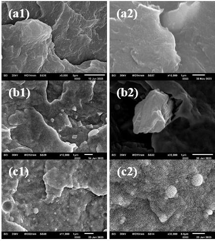
Figure 1. Micrographs of samples: hPP (B_500_10) - magnification of 5,000x (a1) and 15,000x (a2); M_500_10 – magnification of 10,000x (b1) and 25,000x (b2); N_500_10 – magnification of 11,000x (c1) and 30,000x (c2).
hPP; however, this increase was lower than that observed for the nanocomposites up to approximately 5 wt%. Beyond this concentration, the effect of filler content appears to become dominant, leading to a reduction in crystallinity in both micro- and nanocomposite systems. These results are consistent with the literature[35], although they are higher than those obtained by Chan et al.[36] and Eiras[37]
HDT measurements provide valuable insights into how the incorporation of mineral fillers can improve the structural rigidity and thermal endurance of polymers, supporting their application in thermally demanding environments. The incorporation of fillers led to a measurable increase in HDT across all formulations. Notably, the nanocomposite N_500_10 (5 wt%) exhibited the highest thermal deflection performance, reaching temperatures 12 °C above neat hPP and ~3 °C above its microparticulate counterpart, as shown in Figure 3. The results clearly showed that the addition of
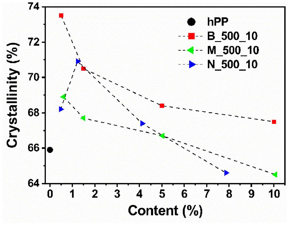
Enhanced thermal and transport properties of PP/CaCO3 micro- and nanocomposites: performance evaluation
nanoparticles was much more efficient in HDT than micro additives, probably due to greater dispersion and interaction with the polymer matrix[35]
Oxidation Onset Temperature (OOT) is a fundamental parameter for characterizing the thermal-oxidative stability of polymers. It defines the temperature at which noticeable oxidative degradation begins, and it is commonly determined using Differential Scanning Calorimetry (DSC). This technique is widely used to assess the performance of antioxidants, forecast material behavior under service conditions, and support the design of more stable and long-lasting polymeric formulations. Figure 4 presents the OOT results obtained for hPP, which exhibited an onset oxidation temperature of 223 °C. In comparison, the B_500_10 sample remained stable at approximately 225 °C, regardless of the compatibilizer concentration. In both composite systems, the OOT values exhibited a gradual decrease with increasing filler content; however, this reduction was more pronounced in the nanocomposite (N_500_10) than in the microcomposite (M_500_10). A review of the available literature revealed a lack of specific studies addressing the influence of CaCO3 on the oxidation onset temperature (OOT) of hPP. Bertini et al.[38] investigated PP nanocomposites containing organophilic montmorillonite (OMMT) and reported that metal ions present in the clay can catalyze oxidative degradation, resulting in a decreased oxidation onset temperature (OOT). Similarly, Fitaroni et al.[39] observed that although thermogravimetric analysis demonstrated enhanced thermal decomposition temperatures with increasing filler content, the Oxidation Induction Time (OIT) measurements indicated a reduction in oxidative stability[38,39]. Regardless, in our case it was observed that both CaCO3 micro and nano additives reduced the thermal stability of the polymer, and this effect was more pronounced at high values of wt% of load, considering the more pronounced effect of concentration for this property.
Additionally, the slope of the tangent line-representing the relationship between heat flow (dQ) and temperature (dT)- indicates the intensity of oxidation propagation. A steeper slope reflects a more vigorous exothermic reaction, as illustrated in Figure 5, which presents the thermal behavior of the composites[5,20,21]
The dQ/dT parameter reflects the oxidation kinetics in polymer composites, being influenced by the filler concentration and particle size. Nanoparticles presented higher dQ/dT and shorter thermal exposure time (OOT), while microparticles were more thermally stable. As shown, the heat flux increased with the addition of filler and is generally higher for nanoparticles. The best performance was observed for the microparticle composite with 1.5 wt% CaCO3, while the nanoparticle composite with 1.2 wt% was more stable.
The flammability test assesses the fire resistance of polymeric materials, playing a crucial role in ensuring safety, regulatory compliance, and minimizing fire-related risks. It also guides the development of flame-retardant formulations and the selection of appropriate materials for applications where the protection of life and property is essential. According to UL94 classification, all samples were designated as Horizontal Burning (HB). The results indicate that neither particle size nor filler content had a significant effect on the burning rate, although a subtle trend was observed. The hPP exhibited the highest burning rate, while B_500_10 showed a slight reduction, likely attributable to the presence of the
compatibilizer. The lowest burning rates were observed in the N_500_10_0.50 composite at low filler content. As illustrated in Figure 6, the addition of the compatibilizing agent along with micro- and nanoparticulate CaCO3 effectively reduced the flammability of composites, as expected[23]
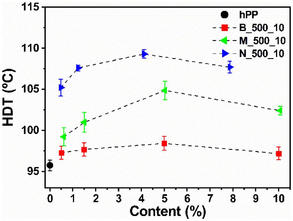
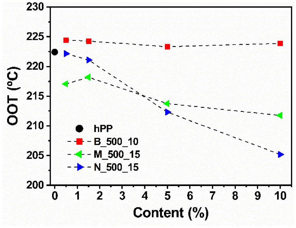
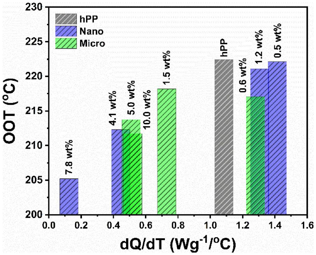
Barbosa, J. M., Peres, R. M., Silva, B. M. O., Andrade, R. J. E., & Ribeiro, H.
The Water Vapor Transmission Rate (WVTR) is a crucial measure of a polymer film’s moisture barrier performance, vital for applications like food packaging, pharmaceuticals, and electronics. Accurate WVTR evaluation guides material selection, ensures regulatory compliance, and supports the development of advanced films with enhanced protective properties, expanding their industrial applicability. As shown in Figure 7, most composites and the compatibilized polymer exhibited increased WVTR values compared to neat hPP. In contrast, a significant reduction in permeability was observed for the N_500_10 composite at 1.5 wt% and the M_500_10 composite at 10 wt%, indicating enhanced barrier performance in these formulations. Although nanofillers are typically associated with improved barrier properties due to their high surface area and ability to create tortuous diffusion paths, the superior performance observed also in composites filled with microparticles at higher concentrations can be attributed to more uniform dispersion and reduced agglomeration. At elevated loadings, microparticles effectively occupy the free volume within the polymer matrix, limiting the mobility of water molecules and reducing permeability. Conversely, poorly dispersed or excessive nanoparticles may form agglomerates and defects, compromise the expected tortuosity and facilitate vapor transport. Therefore, barrier
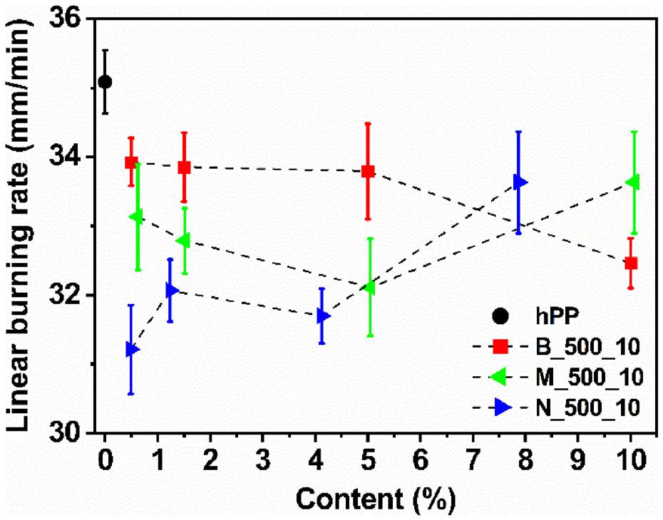
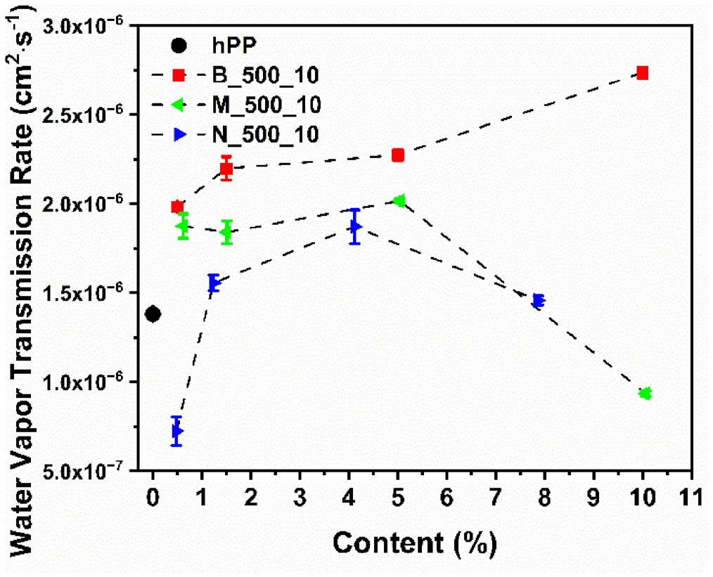
performance depends not only on particle size but also on dispersion quality, filler distribution, and concentration[17,26]
The Oxygen Transmission Rate (OTR) is essential for evaluating polymer films against small molecules, ensuring the protection of oxygen-sensitive products, compliance with standards, and the development of materials with enhanced barrier properties for diverse applications. In this case, the B_500_10 sample showed values comparable to those of hPP, indicating that the compatibilizer concentration had no significant effect on this property. As shown in Figure 8, nearly all composites exhibited higher oxygen permeability than the polymer matrix. Although nanoparticulate composites show a slight decrease in permeability at 1.5 wt%, the overlapping error bars prevent drawing a definitive conclusion. Regarding oxygen permeability, a correlation with the degree of crystallinity is evident: permeability increases as crystallinity decreases, and this variation is dependent on the CaCO3 content[17,25]
Figure 9 presents the correlation between WVTR and OTR values of the samples. The degree of crystallinity may significantly influence the permeability of polymer composites, as higher crystallinity tends to reduce permeability by creating a denser, more ordered structure that limits gas and vapor diffusion. Mineral fillers may act as nucleating
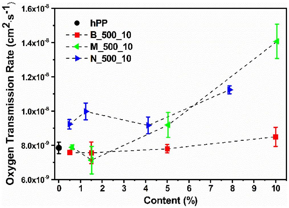
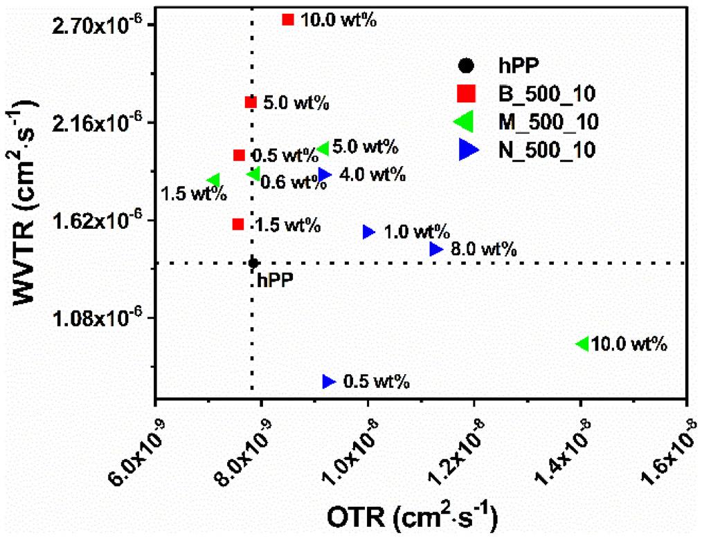
Enhanced thermal and transport properties of PP/CaCO3 micro- and nanocomposites: performance evaluation
agents, promoting crystallite formation and modifying the structural properties of the composite[10,17,25]. However, at higher filler concentrations, interfacial defects may form, leading to increased permeability. For example, composites containing organophilic clay exhibited a 50% reduction in water vapor permeability compared to the PP matrix, while oxygen permeability experienced a slight increase[31]
The incorporation of CaCO3 into PP significantly enhanced both thermal and transport properties, in agreement with previous reports. The composite containing 4.0 wt% CaCO3 exhibited an HDT increase of up to 12 °C, consistent with Al-Samhan et al.[40], who attributed this improvement to the nucleating effect of the nanoparticles. Similarly, the highest crystallinity observed in the composite with 1.2 wt% corroborates the findings of Chafidz[41], highlighting the pronounced nucleation effect at low nanoparticle concentrations. Regarding barrier properties, the nanocomposite with 0.5 wt% CaCO3 reduced oxygen permeability by 52%, in agreement with Al-Attar and Al-Samhan[42] who demonstrated that CaCO3 particles act as effective diffusion barriers. Slight reductions in flammability observed for both nanocomposites and microcomposites align with Subasinghe et al.[43], who attributed to the formation of protective char layers—a residual carbon layer formed during combustion that acts as a physical barrier, reducing heat and oxygen transfer to the underlying material and slowing flame propagation. Overall, the produced nanocomposites outperformed microparticle-filled composites in enhancing thermal and transport properties. However, these improvements are not solely determined by particle size; they are also influenced by compatibilization and filler content, as emphasized by Fuad et al.[44]. These findings collectively demonstrate that carefully optimized nanocomposites can provide superior performance compared to conventional microparticle systems.
This study evaluated the thermal and transport properties of PP/CaCO3 composites containing micro- and nanoparticles, processed at 500 rpm screw speed and 10 kg/h feed rate. The nanocomposite with 4.0 wt% CaCO3 showed an HDT increase of up to 12 °C compared to neat PP, and the highest crystallinity was found in the composite with 1.2 wt%. Although the addition of mineral fillers reduced the OOT more noticeably in nanocomposites, it may indicate lower oxidative stability. Slight reductions in flammability were observed for the nanocomposite with 0.5 wt% and the microcomposite with 5.0 wt%. In terms of barrier properties, the nanocomposite with 0.5 wt% reduced oxygen permeability by 52%, though it did not present the best overall performance. In general, nanofillers improved thermal and transport properties more effectively than microparticles. However, these improvements are not solely dependent on particle size, but also on factors such as compatibilization and filler content. Further studies are needed to better understand these relationships
5. Author’s Contribution
• Conceptualization – Juliano Martins Barbosa; Renato Meneghetti Peres; Bruno Milton Oliveira Silva; Ricardo Jorge Espanhol Andrade; Hélio Ribeiro.
• Data curation – Juliano Martins Barbosa; Hélio Ribeiro.
• Formal analysis – Juliano Martins Barbosa; Renato Meneghetti Peres; Bruno Milton Oliveira Silva; Ricardo Jorge Espanhol Andrade; Hélio Ribeiro.
• Funding acquisition - Juliano Martins Barbosa; Hélio Ribeiro.
• Investigation – Juliano Martins Barbosa; Hélio Ribeiro.
• Methodology – Juliano Martins Barbosa; Hélio Ribeiro.
• Project administration – Juliano Martins Barbosa; Hélio Ribeiro.
• Resources – Juliano Martins Barbosa; Renato Meneghetti Peres; Bruno Milton Oliveira Silva; Hélio Ribeiro.
• Software – N/A.
• Supervision – Juliano Martins Barbosa; Hélio Ribeiro.
• Validation – Juliano Martins Barbosa; Renato Meneghetti Peres; Bruno Milton Oliveira Silva; Ricardo Jorge Espanhol Andrade; Hélio Ribeiro.
• Visualization – Juliano Martins Barbosa; Renato Meneghetti Peres; Bruno Milton Oliveira Silva; Ricardo Jorge Espanhol Andrade; Hélio Ribeiro.
• Writing – original draft – Juliano Martins Barbosa; Hélio Ribeiro.
• Writing – review & editing – Juliano Martins Barbosa; Renato Meneghetti Peres; Bruno Milton Oliveira Silva; Ricardo Jorge Espanhol Andrade; Hélio Ribeiro.
6. Acknowledgements
This study received partial funding from the Coordenação de Aperfeiçoamento de Pessoal de Nível Superior - Brasil (CAPES) - Conselho Nacional de Desenvolvimento Científico e Tecnológico (CNPq, Project No. 305109/2022-7 and 303139/2024-2), Mackenzie Research Fund (Mackpesquisa, Project No. 231021, 0012510), and (Project No. 2310150012510/002). Fundação de amparo à pesquisa do estado de São Paulo (FAPESP, Project No. 2023/08110-1. The authors extend their gratitude to the Materials Engineering Department (DEMa) of Federal University of São Carlos (UFSCar), as well as ZwickRoell and Netzsch - Analyzing and Testing for their invaluable technical support and collaboration in supplying the equipment utilized in this study and Cromex S/A, for raw material donation.
7. References
1 Rabelo, M. (2000). Aditivação de polímeros São Paulo: Artliber Editora
2 Wypych, G. (1999). Handbook of fillers. New York: Plastics Design Library
3 Rodolfo, A., Nunes, L. R., & Ormanji, W. (2006). Tecnologia do PVC. São Paulo: ProEditores Associados
4 Mai, Y. W., & Yu, Z.-Z. (Eds.). (2006). Polymer nanocomposites Cambridge: Woodhead Publishing
5 Barbosa, J. M. (2011). Estudo das propriedades mecânicas, térmicas e de transporte do compósito com carbonato de cálcio nano e microparticulado em polipropileno (Master’s dissertation). Universidade Federal de São Carlos, São Carlos Retrieved in 2025, July 5, from https://repositorio.ufscar.br/ handle/ufscar/15929
Barbosa, J. M., Peres, R. M., Silva, B. M. O., Andrade, R. J. E., & Ribeiro, H.
6 Ribeiro, H., Silva, W. M., Neves, J. C., Calado, H. D. R., Paniago, R., Seara, L. M., Camarano, D. M., & Silva, G. G. (2015). Multifunctional nanocomposites based on tetraethylenepentaminemodified graphene oxide/epoxy. Polymer Testing, 43, 182-192 https://doi.org/10.1016/j.polymertesting.2015.03.010
7. Silva, B. M. O., Fernandes, N. M. M., Barbosa, J. M., Pinto, G. M., Benega, M. A. G., Taha-Tijerina, J. J., Andrade, R. J. E., & Ribeiro, H. (2024). Thermomechanical properties of multifunctional polymer hybrid nanocomposites based on carbon nanotubes and nanosilica. Journal of Applied Polymer Science, 141(41), e56054 https://doi.org/10.1002/app.56054
8 Móczó , J. , & Pukánszky, B. (2019 ). Particulate filled polypropylene: structure and properties. In J. Karger-Kocsis, & T. Bárány (Eds.), Structure an polypropylene handbook: morphology, blends and composites (pp. 357-417). Cham: Springer https://doi.org/10.1007/978-3-030-12903-3_7
9. Barbosa, J. M., Beatrice, C. A. G., & Pessan, L. A. (2022). Influence of carbon black trimodal mixture on LDPE films properties: Part1 – DOE. Polímeros: Ciência e Tecnologia, 32(3), e2022029 https://doi.org/10.1590/0104-1428.20220039
10 Barbosa, J. M., Beatrice, C. A. G., & Pessan, L. A. (2022). Influence of carbon black trimodal mixture on LDPE films properties: Part2 – SME. Polímeros: Ciência e Tecnologia, vol. 32, no. 3, e2022030 https://doi.org/10.1590/01041428.20220053
11 Yang, K., Yang, Q., Li, G., Sun, Y., & Feng, D. (2006). Morphology and mechanical properties of polypropylene/ calcium carbonate nanocomposites. Materials Letters, 60(7), 805-809 https://doi.org/10.1016/j.matlet.2005.10.020
12 Huang, Z., Lin, Z., Cai, Z., & Mai, K. (2004). Physical and mechanical properties of nano-CaCO3/PP composites modified with acrylic acid. Plastics, Rubber and Composites, 33(8), 343-352 https://doi.org/10.1179/174328904X22314
13 Barbosa, J. M. (2021). Influência da incorporação de negro de fumo e carbonato de cálcio micro e nanoparticulado nas propriedades reológicas, colorimétricas e mecânicas de filmes de polietileno de baixa densidade (Doctoral thesis). Universidade Federal de São Carlos, São Carlos. Retrieved in 2025, July 5, from https://repositorio.ufscar.br/handle/20.500.14289/16924
14 Demjén, Z., Pukánszky, B., & Nagy, J. (1998). Evaluation of interfacial interaction in polypropylene/surface treated CaCO3 composites. Composites. Part A, Applied Science and Manufacturing, 29(3), 323-329 https://doi.org/10.1016/ S1359-835X(97)00032-8
15 Fischer, H. (2003). Polymer nanocomposite: from fundamental research to specific applications. Materials Science and Engineering C, 23(6-8), 763-772 https://doi.org/10.1016/j. msec.2003.09.148
16 Jiang, L., Lam, Y. C., Tam, K. C., Chua, T. H., Sim, G. W., & Ang, L. S. (2005). Strengthening acrylonitrile-butadienestyrene (ABS) with nano-sized and micron-sized calcium carbonate. Polymer, 46(1), 243-252 https://doi.org/10.1016/j. polymer.2004.11.001
17 Sakahara, R., Lima, A., & Wang, S. H. (2014). Influence of the beta crystalline phase fraction on the mechanical behavior of polypropylene/calcium carbonate/polypropylene-graft-maleic anhydride composites. Polímeros: Ciência e Tecnologia, 24(5), 554-560 https://doi.org/10.1590/0104-1428.1692
18 Avella, M., Cosco, S., Di Lorenzo, M. L., Di Pace, E., Errico, M. E., & Gentile, G. (2006). Nucleation activity of nanosized CaCO3 on crystallization of isotactic PP: dependence on crystal modification, particle shape, and coating. European Polymer Journal, 42(6), 1548-1557 https://doi.org/10.1016/j. eurpolymj.2006.01.009.
19 Zhang, Q.-X., Yu, Z.-Z., Xie, X.-L., & Mai, Y.-W. (2004). Crystallization and impact energy of polypropylene/CaCO3
nanocomposites with nonionic modifier. Polymer, 45(17), 5985-5994 https://doi.org/10.1016/j.polymer.2004.06.044
20 Barbosa, J. M., Pacheco, C. V., Szilagyi, G., Oliveira, P. C. M., Peres, R. M., & Ribeiro, H. (2022). Mechanical properties of polypropylene/calcium carbonate micro and nanocomposites. In 17th Brazilian Polymer Congress (CBPol), Joinville, Brazil
21 Barbosa, J. M., Pacheco, C. V., Szilágyi, G., Oliveira, P. C., Peres, R. M., & Ribeiro, H. (2024). Micro and nanoparticulate PP/CaCO3 composites mechanical, thermal and transport properties - DOE. Polímeros: Ciência e Tecnologia, 35(1), e20250003 https://doi.org/10.1590/0104-1428.20240071
22 Alves, T. S., Barbosa, R., Carvalho, L. H., & Canedo, E. L. (2014). Inflamabilidade de nanocompósitos de polipropileno/ argila organofílica. Polímeros: Ciência e Tecnologia, 24(3), 334-340. https://doi.org/10.4322/polimeros.2014.030.
23 Alberton, J. (2008). Preparação e caracterização de compósitos de polipropileno, carbonato de cálcio e poli(etileno-co-acetato de vinila) utilizados na produção de chapas termoplásticas (Master’s dissertation). Universidade Federal de Santa Catarina, Florianópolis. Retrieved in 2025, July 5, from https://repositorio. ufsc.br/handle/123456789/91059
24 Hadi, N. J., Saad, N. A., & Mohamed, D. J. (2016). Thermal behavior of calcium carbonate and zinc oxide nanoparticles filled polypropylene by melt compounding. Research Journal of Applied Sciences, Engineering and Technology, 13(4), 265272 https://doi.org/10.19026/rjaset.13.2941
25 Loste, J., Lopez-Cuesta, J.-M., Billon, L., Garay, H., & Save, M. (2019). Transparent polymer nanocomposites: an overview on their synthesis and advanced properties. Progress in Polymer Science, 89, 133-158 https://doi.org/10.1016/j. progpolymsci.2018.10.003
26. Al-Samhan, M., & Al-Attar, F. (2022). Comparative analysis of the mechanical, thermal, and barrier properties of polypropylene incorporated with CaCO3 and nano CaCO3 Surfaces and Interfaces, 31, 102055 https://doi.org/10.1016/j. surfin.2022.102055
27 Kamal, M., Sharma, C. S., Upadhyaya, P., Verma, V., Pandey, K. N., Kumar, V., & Agrawal, D. D. (2012). Calcium carbonate (CaCO3) nanoparticle filled polypropylene: effect of particle surface treatment on mechanical, thermal, and morphological performance of composites. Journal of Applied Polymer Science, 124(4), 2649-2656 https://doi.org/10.1002/app.35319
28 American Society for Testing and Materials – ASTM. (2006). ASTM D648-06: standard test method for deflection temperature of plastics under flexural load in the edgewise position. West Conshohocken: ASTM https://doi.org/10.1520/D0648-18
29 American Society for Testing and Materials – ASTM. (2008). ASTM E2009-08: standard test method for oxidation onset temperature of hydrocarbons by differential scanning calorimetry. West Conshohocken: ASTM https://doi.org/10.1520/E200908
30 American National Standards Institute – ANSI. (2024). UL 94: tests for flammability of plastics materials for parts and devices and appliances. Washington, D.C.: ANSI
31 Morelli, F. C. (2009). Nanocompósito de PP/PP-g-AM/argila organofílica: processamento, propriedades mecânicas, termomecânicas e de permeação de gás (Master’s dissertation). Universidade Federal de São Carlos, São Carlos
32. American Society for Testing and Materials – ASTM. (2024). ASTM E96/E96M-24a: standard test methods for gravimetric determination of water vapor transmission rate of materials. West Conshohocken : ASTM https://doi.org/10.1520/ E0096_E0096M-24A
33 Atkins, P. W. (1990). Physical chemistry. Oxford: Oxford University Press
Polímeros, 36(1), e20260008, 2026
Enhanced thermal and transport properties of PP/CaCO3 micro- and nanocomposites: performance evaluation
34 American Society for Testing and Materials – ASTM. (2024). ASTM D3985: standard test method for oxygen gas transmission rate through plastic film and sheeting using a coulometric sensor. West Conshohocken: ASTM https://doi.org/10.1520/ D3985-24
35 Rothon, R. N. (Ed.). (2003). Particulate filled polymer composites. Shrewsbury: Rapra Technology.
36 Chan, C.-M., Wu, J., Li, J.-X., & Cheung, Y.-K. (2002). Polypropylene/calcium carbonate nanocomposite. Polymer, 43(10), 2981-2992 https://doi.org/10.1016/S0032-3861(02)00120-9
37. Eiras , D. ( 2009 ). Tenacificação de polipropileno com nanopartículas de carbonato de cálcio (Master’s dissertation). Universidade Federal de São Carlos, São Carlos
38 Bertini, F., Canetti, M., Audisio, G., Costa, G., & Falqui, L. (2006). Characterization and thermal degradation of polypropylene-montmorillonite nanocomposites. Polymer Degradation & Stability, 91(3), 600-605 https://doi.org/10.1016/j. polymdegradstab.2005.02.027
39 Fitaroni, L. B., Lima, J. A., Cruz, S. A., & Waldman, W. R. (2015). Thermal stability of PP–montmorillonite clay nanocomposites: limitation of the TA. Polymer Degradation & Stability , 111 , 102 - 108 https://doi.org/10.1016/j. polymdegradstab.2014.10.016
40 Al-Samhan, M., Al-Attar, F., Al-Fadhli, J., & Al-Shamali, M. (2021). The influence of nano-CaCO3 on nucleation and interface of PP nanocomposite: matrix processability and impact
resistance. Polymers, 13(9), 1389 https://doi.org/10.3390/ polym13091389 PMid:33922878.
41 Chafidz, A. (2022). Effect of nano-CaCO3 loadings and reprocessing on the melting properties of polypropylene/calcium carbonate nanocomposites. Materials Science Forum, 1067, 73-78 https://doi.org/10.4028/p-2u9f04
42 Al-Attar, F., & Al-Samhan, M. (2022). Nano CaCO3 incorporation with polypropylene to reduce film water vapor permeability for packaging application. Asian Journal of Scientific Research, 13(4), 275-283. https://doi.org/10.3923/ajsr.2020.275.283.
43 Subasinghe, A., Das, R., & Bhattacharyya, D. (2016). Study of thermal, flammability and mechanical properties of intumescent flame-retardant PP/kenaf nanocomposites. International Journal of Smart and Nano Materials, 7(3), 202-220 https://doi.org/10. 1080/19475411.2016.1239315
44 Fuad, M. Y. A., Hanim, H., Zarina, R., Ishak, Z. A. M., & Hassan, A. (2010). Polypropylene/calcium carbonate nanocomposites: effects of processing techniques and maleated polypropylene compatibilizer. Express Polymer Letters, 4(10), 611-620 https:// doi.org/10.3144/expresspolymlett.2010.76
Received: Jul. 05, 2025
Revised: Oct. 04, 2025
Accepted: Nov. 14, 2025
Editor-in-Chief: Sebastião V. Canevarolo
Febriani Purba1* , Ono Suparno2 , Meika Syahbana Rusli2 and Is Fatimah3
1Department of Agricultural Industrial Technology, Universitas Lambung Mangkurat, Banjarbaru, Indonesia
2Department of Agricultural Industrial Technology, IPB University, Bogor, Indonesia
3Department of Chemistry, Universitas Islam Indonesia, Yogyakarta, Indonesia
*febriani.purba@ulm.ac.id
Obstract
Slow-release urea fertilizer (SRUF) with gradual nitrogen release and high water absorption capacity was synthesized in situ by incorporating urea into a superabsorbent hydrogel matrix of h-collagen-g-poly(acrylic acid). The water absorption capacity of the product was 110 (g/g) times its weight in distilled water at room temperature over 90 minutes. Nitrogen content analysis indicated that the product contained 5.58% nitrogen. The water-holding properties of the product and nitrogen-release behavior in soil and water media were also investigated. The findings indicate that the product exhibits good slow-release properties and excellent water retention capacity. This will efficiently enhance fertilizer utilization and water resource management simultaneously.
Keywords: slow-release fertilizer, superabsorbent hydrogel polymer, urea, collagen hydrolysate.
Data Ovailability: All data supporting the findings of this study are available from the corresponding author upon request.
How to cite: Purba, F., Suparno, O., Rusli, M. S., & Fatimah, I. (2026). Bio-based hydrogel fertilizer from h-collagen-g-PAA for water retention and urea management. Polímeros: Ciência e Tecnologia , 36 (1), e20260009. https://doi.org/10.1590/0104-1428.20250090
The global agricultural sector faces challenges due to the excessive application of urea fertilizer and water scarcity during the dry season[1,2]. Conventional urea fertilizer enhances soil nitrogen (N) content but is inefficient[3,4] Approximately 40-70% of N is lost to the environment or chemically bound in the soil, unavailable to plants, leading to economic losses, environmental pollution, and agroecological issues[5-7]. Previous studies have shown that the use of slow-release fertilizers and superabsorbent hydrogel polymers can effectively address these issues[8-11]. Integrating superabsorbent hydrogels (SAP) with fertilizers improves plant nutrition, minimizes the environmental impact of fertilizers, decreases evaporation, and reduces irrigation frequency[12] . SAP are hydrophilic networks capable of absorbing and retaining significant quantities of water or aqueous solutions[13 14]. Hydrogels function as reservoirs for water conservation that work near the root zone of plants. During irrigation, whether from irrigation water or rainwater, water can be collected, stored, and then released gradually to meet the plants’ needs over an extended period after irrigation. Hydrogels combined with soil enhance air permeability, improve water absorption, and increase fertilizer retention, yielding economic advantages[15]. However, using hydrogels in agriculture encounters multiple challenges, as most are composed of pure poly(sodium acrylate), which is costly,
non-biodegradable, and unsuitable for environments with water and soil salts[16]
Multiple studies indicate that incorporating collagen hydrolysate (h-collagen) in the synthesis of superabsorbent hydrogel polymers enhances their swelling properties, lowers production costs, and results in biodegradable hydrogel polymers[17-20]. H-collagen was selected as the hydrogel skeleton due to its biodegradability, abundance, and potential as a sustainable raw material derived from tannery waste. The present study is a continuation of our previous works on the extraction of collagen from leather trimming waste and the synthesis of superabsorbent hydrogels from the extracted collagen[20,21]. Utilizing h-collagen derived from tanning industry by-products not only provides an environmentally friendly approach to waste management but also adds economic value to an otherwise discarded material, aligning with the principles of circular economy and sustainable agriculture.
Research on the coating of urea fertilizer with SAP polymers derived from h-collagen produced from leather industry solid waste has not been found in the literature. Bajpai and Giri[22] stated that there are two methods for coating fertilizer with hydrogel. The first method entails incorporating the compound (fertilizer) into the reaction mixture, where polymerization occurs in situ, encapsulating the fertilizer within the gel matrix. The second method allows the dry polymer gel to swell in a fertilizer solution.
Purba, F., Suparno, O., Rusli, M. S., & Fatimah, I.
Once equilibrium is achieved, the gel is dried, producing a superabsorbent that contains fertilizer[16]. This study employed the first method due to its greater efficiency in implementation.
Therefore, this study aimed to develop a biodegradable slow-release urea fertilizer (SRUF) synthesized in situ using h-collagen as a natural biopolymer backbone. The main objectives were to: (1) fabricate an h-collagen-based SRUF composite, (2) evaluate its swelling behavior, water retention, and nitrogen release characteristics, and (3) analyze its release kinetics using established kinetic models. The significance of this research lies in introducing a sustainable, waste-derived biopolymer for fertilizer encapsulation, which not only reduces nutrient loss and improves water management in soil but also promotes the valorization of tannery waste, contributing to circular bioeconomy and sustainable agricultural practices.
2.1 Tools and materials
The materials used were h-collagen, methylene bisacrylamide (MBA), potassium persulfate (KPS), acrylic acid (AA), 2-acrylamido-2-methylpropane sulfonic acid (AMPS), distilled water, ethanol, Merck urea (p.a), and ultisol soil. The soil was obtained from the research field of the Faculty of Agriculture, Lambung Mangkurat University, located at Jl. Unlam III, Banjarbaru City, South Kalimantan. The collected soil was cleaned of leaves and non-soil materials, sieved through a 26-mesh sieve and airdried overnight. H-collagen was synthesized following the method described in our previous study[21]. The equipment used included a three-neck reactor, a magnetic stirrer, a thermostatic water bath, a vacuum apparatus, scissors, an oven, nylon cloth, and polyester gauze.
2.2 Production of slow-release urea fertilizer (SRUF) urea in situ
This method was based on modifications of Purba et al.[20] H-collagen (1.33 g) was dissolved in 40 mL of distilled water, placed in a three-neck reactor equipped with a mechanical stirrer (300 rpm) and immersed in a thermostatic water bath at 80 °C. Subsequently, a certain amount of 70% neutralized AA (4.7 g in 5 mL H2O) and 2 g of urea were added and stirred for 10 minutes. After that, a crosslinker solution (0.14 g MBA in 5 mL H2O) and an initiator solution (0.15 g KPS in 5 mL H2O) were added successively. The reaction was conducted for 60 minutes at 80 °C and 300 rpm. The entire reaction was conducted under vacuum conditions. After the reaction was complete, the gel formed was poured into excess ethanol (200 mL) and left to stand overnight. The product was then reduced in size using scissors, washed with 200 mL of fresh ethanol, and filtered. The product was dried in an oven at 50 °C for one night. After drying, the sample was stored away from moisture, heat, and light. Three independent batches of SRUF were synthesized to account for experimental variability.
One gram of SRUF was immersed in tap water and left to soak at room temperature for 90 minutes. The swollen
SRUF was filtered through an 80-mesh sieve to eliminate unabsorbed water and subsequently weighed. Water absorption was calculated using Equation 1. Each measurement was performed in triplicate, and the average value was reported.
where: M indicates the weight of swollen SRUF; M0 indicates the weight of dry SRUF; and WA is the water absorption capacity per gram of dry SRUF.
SRUF sample (1 g) was mixed with 100 g of dry ultisol soil (under 26 mesh) and placed in a PVC tube with a diameter of 4.5 cm. The bottom of the tube was sealed with nylon cloth (with an aperture of 0.076 mm) and weighed (marked W1). The soil sample was slowly moistened with tap water from the top of the tube until water seeped out from the bottom. The tube was reweighed (marked W2) when no water seeped from the bottom. A control experiment was conducted without SRUF. The maximum water holding ratio (Wt %) of the soil was determined using Equation 2. The experiment was conducted with three replicates for each treatment (with and without SRUF).
( ) ( ) %10021/21200 wtWWWW=−−+ (2)
Ten grams of filtered soil were mixed with 1 gram of SRUF. The mixture was placed in a 5 cm diameter PVC tube lined with nylon cloth at the bottom and fitted with a device to collect liquid. Regular watering with 20 mL of distilled water was conducted daily for 10 days. The solution that had passed through the soil (leachate) was collected daily to analyze the total nitrogen value using the micro-Kjeldahl method. Urea release in soil was tested in triplicate.
2.6 Urea release in water media
A total of 0.5 grams of SRUF was placed in a beaker glass filled with 1000 mL of distilled water. Water samples of 2 mL were collected at intervals of 0, 5, 10, 15, 20, 25, 30, 35, 40, 45, 50, 60, 90, and 120 minutes. The water samples were placed in glass containers and stored at 5 °C until the next nitrogen (total N) concentration test. Each test was repeated three times independently, and the average results were reported.
Release kinetics can describe the rate of nitrogen release and its release model. This is an important parameter in SRUF because it determines its effectiveness. This study evaluated nitrogen release kinetics using four models: Zero Order, First Order, Higuchi Order, and the Korsmeyer-Peppas model. Kinetic parameters were calculated based on the mean values obtained from three replicate experiments.
2.8 Zero order reaction kinetics
In this zero-order system, nitrogen is released at a constant rate, regardless of concentration. The zero-order release
Bio-based hydrogel fertilizer from h-collagen-g-PAA for water retention and urea management
system is ideal for SRUF (sustained release). Zero-order kinetics follow Equation 3[23]. The graph derived from this equation represents a linear function. In zero-order kinetics, the dissolution profile is slow due to the absence of system separation, assuming that the dissolution area remains under equilibrium conditions[23]. Zero-order kinetics is obtained by plotting the cumulative percentage of nitrogen release against time[24,25].
100 QQkt =+ (3)
where: Q1 indicates nitrogen concentration; k0 indicates zero-order constant; and t is time.
This kinetic model is founded on Fick’s law. It describes the release of a solute when a combination mechanism occurs between Fickian diffusion transport and non-Fickian Case II transport controlled by polymer chain relaxation. This model is commonly applied to analyze the release of a substance in a polymeric system[23]. Kottegoda et al.[25] indicate that the graph produced by this method illustrates the relationship between time and the fractional release of nitrogen, plotted as the logarithm of nitrogen release against the logarithm of time. The kinetics of the Korsmeyer-Peppas model is described by Equation 4.
3.1
The preliminary study evaluated two methods for the production of SRUF. The initial method employed by Sarkar et al.[26] consisted of coating urea with dry hydrogel. This method necessitated the use of a rotary drum to ensure even distribution of the hydrogel powder on the surface of the urea granules. Due to the unavailability of the rotary drum in the laboratory, it was substituted with a simpler device that involved stirring in a closed container using a clockwise rotating motion. The resulting SRUF exhibited an irregular size. The second method evaluated was a modification of the approaches by Purba et al.[20]. This method is efficient in terms of time, as urea is incorporated during the hydrogel formation process, which is why it is also known as in situ synthesis. This method yields SRUF with a more consistent size compared to the prior method. This method was chosen for the production of SRUF.
One of the most important characteristics of the SRUF is its slow-release property. The nitrogen release rate in the soil medium is presented as accumulation (Figure 1). The nitrogen content, calculated using the micro-Kjeldahl method, is expressed as a percentage (%) and converted into cumulative nitrogen (g). The cumulative value represents the quantity of nitrogen that can be released from the produced SRUF. In addition, measurements were also conducted on nitrogen release from pure urea fertilizer (Merck p.a).
The release of nitrogen from pure urea fertilizer is faster than that from SRUF. Nitrogen is highly volatile and easily washed away, potentially leading to environmental pollution that disrupts ecosystem balance[27 28]. Experimental results showed that conventional urea released approximately 91% of its total nitrogen content within 10 days, whereas the SRUF released only about 47% over the same period. Unlike urea fertilizer, the SRUF generated in this study could release nitrogen slowly and consistently. The slower the nitrogen release, the smaller the fertilizer loss due to evaporation and leaching. Therefore, plants are expected to absorb the nitrogen contained in SRUF optimally. In addition to its slow nitrogen release capability, the SRUF exhibits a swelling ratio of 110.8 g/g when tested in distilled water.
The mechanism by which urea is slowly released from SRUF in the soil is as follows. SRUF will gradually expand as water is added to the soil, transforming into hydrogel. This causes an increase in the size of the three-dimensional layer openings and allows the diffusion of fertilizer solution in the hydrogel network. Urea in SRUF is slowly dissolved by water in the swollen hydrogel network. Additionally, urea release is influenced by dynamic exchange between free water in the hydrogel and soil water[29-31].
According to recent studies the nitrogen release behavior of polymer-based slow-release fertilizers is mainly influenced by water diffusion, polymer relaxation, and matrix degradation[32,33]. The hydrogel network formed by h-collagen, acrylic acid, and AMPS contains hydrophilic functional groups (–COOH, –NH2, and –SO3H) that establish hydrogen bonding and electrostatic interactions with urea molecules. These interactions temporarily immobilize urea within the network, delaying its diffusion. Meanwhile, the hydrogen-bonded water molecules within the hydrogel enhance the material’s water retention and holding capacity, providing a moist microenvironment that facilitates gradual nutrient release. As the hydrogel undergoes repeated swelling and deswelling cycles, the network relaxation and partial degradation further promote a sustained and predictable nitrogen release profile, consistent with diffusion-controlled and polymer-relaxation mechanisms reported in the literature.
The kinetics of nitrogen release from SRUF were estimated by plotting a curve between the cumulative amount of nitrogen and time. These values were then compared with the kinetics of nitrogen release from pure urea.
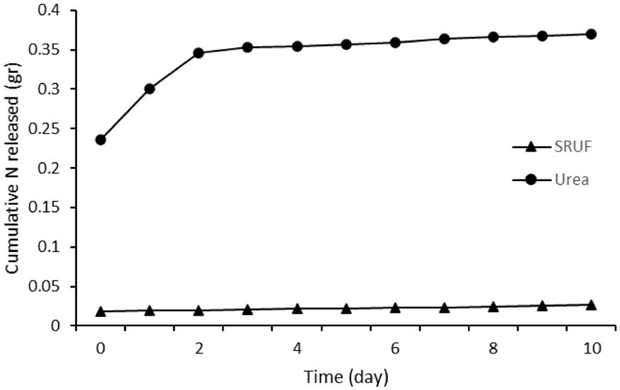
Purba, F., Suparno, O., Rusli, M. S., & Fatimah, I.
The nitrogen release data were fitted to Zero-order, First-order, Higuchi, and Korsmeyer–Peppas models to determine the best-fit release kinetics based on linear regression analysis. The best-fitting model was determined based on the coefficient of determination (R2) of each regression, which indicates the proportion of total variation in the dependent variable explained by the independent variable, with values ranging from 0 to 1[34]. A model is deemed a good fit when R2 approaches one. Figure 2 displays the kinetic graphs for each tested model.
The values of the release rate coefficient (k) and diffusion exponent (n) were obtained from the processing of dissolution data into the equation y = a + bx. For zeroorder kinetics, b was the parameter; for first-order kinetics, it was -b/2.303; the Higuchi order was represented by b; and in the Kormeyer-Peppas model, n equaled b[35] Table 1 summarizes the equations and R2 values for each kinetic model tested. The data in Table 1 indicate that the highest R2 value for SRUF achieved in this study, approaching one, corresponds to the zero-order release kinetics model. Therefore, the Zero-Order model is highly suitable for describing the nitrogen release kinetics from SRUF. Nitrogen release following Zero-Order kinetics exhibits a nitrogen release rate independent of the initial nitrogen concentration in SRUF and remains constant over time[36,37]
The maximum water-holding ratio of Ultisol soil was significantly improved by the incorporation of SRUF. In soil without SRUF, the maximum water-holding ratio was 20.89%, whereas the addition of SRUF at a mass ratio of 1:100 (SRUF to soil) increased this value to 46.67%.
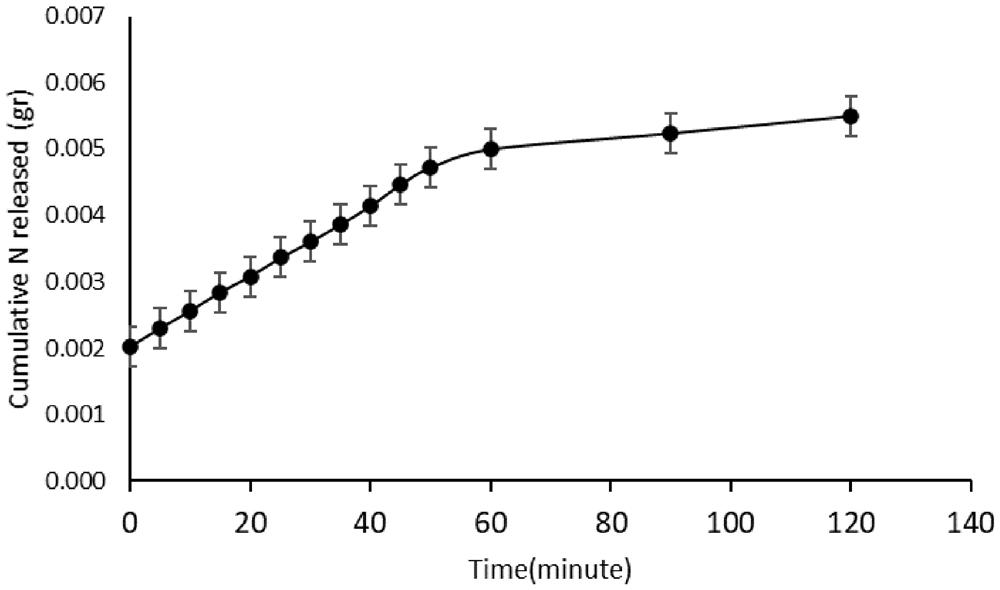
This represents a 25.78% enhancement in water retention compared with the control soil. The improvement achieved in this study exceeds those reported in previous works. For instance, Guo et al.[2] reported a 12.45% increase in water-holding capacity with polymer-coated fertilizers, and Guo et al.[38] observed an 11.3% increase.
The SRUF produced in this study demonstrates a high water absorption capacity in the soil, enhances the soil’s water holding capacity, and effectively stores rainwater or irrigation water, thus improving the efficiency of water resource utilization. This value exceeds that reported in earlier studies, representing a notable advantage over traditional slow-release fertilizers.
Similar mechanisms have been reported in recent studies, where hydrogen bonding, polymer relaxation, and reversible swelling–deswelling cycles play a major role in sustaining water retention in polymer-based fertilizers[32,33]. Moreover, the incorporation of h-collagen contributes to improved structural flexibility and mechanical stability, allowing repeated swelling and shrinking without disintegration. This synergistic behavior enhances both the durability and efficiency of the SRUF in regulating soil water dynamics.
Overall, the SRUF developed in this study demonstrates a substantial improvement in the soil’s ability to retain and regulate water compared with conventional fertilizers. This improvement supports sustainable soil–water management practices and offers a promising approach to improving fertilizer efficiency under varying environmental conditions.
3.5 Morphological observation of SRUF before and after water absorption and soil incubation
Morphological observations were conducted to visually support the functional performance of SRUF, particularly in terms of water absorption and nitrogen release mechanisms. Figure 3A shows the SRUF in its dry state, appearing as firm, opaque, and compact granules. After being immersed in distilled water for 90 minutes (Figure 3B), the SRUF exhibited a substantial increase in volume, forming a transparent hydrogel structure. This morphological transformation indicates the material’s strong hydrophilic nature and confirms the crosslinked hydrogel network’s ability to absorb and retain large quantities of water. Following ten days of incubation in Ultisol soil with daily watering (Figure 3C), the SRUF maintained its swollen hydrogel form but showed partial surface degradation and a darker coloration. These changes suggest water exchange between the hydrogel and
Bio-based hydrogel fertilizer from h-collagen-g-PAA for water retention and urea management
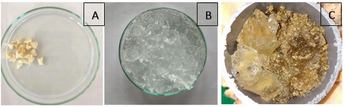
the surrounding soil environment, consistent with nitrogen diffusion from the SRUF matrix to the soil solution. The partial degradation further demonstrates the biodegradable characteristics of the collagen-based hydrogel, which aligns with the sustainable design objective of this material.
These visual observations are consistent with previous findings on collagen-based hydrogels, where morphological changes during swelling and soil interaction are attributed to the diffusion-controlled release of urea and gradual polymer relaxation within the hydrogel matrix[32,33].
The nitrogen release profile of SRUF in distilled water at room temperature indicates that 20% of nitrogen was released into the medium within 120 minutes. As illustrated in Figure 2, SRUF exhibited a steady and gradual release pattern, indicating that the hydrogel matrix was able to withstand the internal pressure generated by the dissolution of urea and maintain its structural integrity during immersion. This behavior demonstrates that the nitrogen release in aqueous conditions is predominantly governed by diffusion through the swollen hydrogel network rather than by rapid dissolution of urea.
The kinetic graphs of each tested model are presented in Figure 2. A summary of the equations, R2 values, and n values of each kinetic model tested in water are presented in Table 2. The nitrogen release profile of SRUF in water tends to follow the Korsmeyer-Peppas kinetic release model with an R2 value closest to 1. In the Korsmeyer-Peppas equation, the parameter n characterizes the mechanism of nitrogen release. Table 3 illustrates the relationship between n and the nitrogen release mechanism. Table 2 shows that
Table 3. Relationship between the release exponent (n) and the release mechanism.
< 0.5
Release exponent (n) Release mechanism
Quasi-Fickian
0.5 Fickian
0.5 < n < 1
Anomalous (non-Fickian) 1 Non-Fickian case II > 1
Non-Fickian super case-II
the value of n = 0.3133 indicating that the nitrogen release mechanism from SRUF in water is based on quasi-Fickian diffusion. This suggests that the release behavior is controlled by a combination of water penetration into the hydrogel and the diffusion of urea through the partially relaxed polymeric chains.
SRUF derived from the coating of urea with the superabsorbent hydrogel polymer h-collagen-g-poly(acrylic acid) has been successfully produced. SRUF contains 5.58% nitrogen with a water absorption capacity of approximately 110.8 (g/g) of its weight in distilled water. SRUF has a water retention capacity of 27.78% higher than water without SRUF. Nitrogen release from SRUF in soil medium is significantly slower compared to pure urea fertilizer. SRUF releases approximately 45% of nitrogen over a period of 10 days. whereas urea fertilizer releases 83%. Thus. the SRUF produced in this study can be classified as a slowrelease fertilizer. In water medium testing. SRUF releases approximately 47% of nitrogen over 120 minutes. Based on the release kinetics observed. there are differences in kinetic models between SRUF produced and urea fertilizer.
Purba, F., Suparno, O., Rusli, M. S., & Fatimah, I.
The release kinetics of SRUF in soil medium follow the Zero-Order kinetic model with an R2 value of 0.9996. In contrast. it follows the Korsmeyer-Peppas model in a water medium with an R2 value of 0.9559.
5. Author’s Contribution
• Conceptualization – Febriani Purba
• Data curation – Febriani Purba
• Formal analysis – Febriani Purba
• Funding acquisition – Ono Suparno
• Investigation – Febriani Purba
• Methodology – Febriani Purba
• Project administration – Febriani Purba
• Resources – Febriani Purba
• Software – NA.
• Supervision – Ono Suparno; Meika Syahbana Rusli; Is Fatimah
• Validation – Ono Suparno; Meika Syahbana Rusli; Is Fatimah
• Visualization – Febriani Purba
• Writing – original draft – Febriani Purba.
• Writing – review & editing – Febriani Purba; Ono Suparno; Meika Syahbana Rusli, Is Fatimah.
6. References
1 Qiao, D., Liu, H., Yu, L., Bao, X., Simon, G. P., Petinakis, E., & Chen, L. (2016). Preparation and characterization of slowrelease fertilizer encapsulated by starch-based superabsorbent polymer. Carbohydrate Polymers, 147, 146-154 https://doi. org/10.1016/j.carbpol.2016.04.010 PMid:27178919.
2 Guo, M., Liu, M., Zhan, F., & Wu, L. (2005). Preparation and properties of a slow-release membrane-encapsulated urea fertilizer with superabsorbent and moisture preservation. Industrial & Engineering Chemistry Research, 44(12), 42064211 https://doi.org/10.1021/ie0489406
3 Shaviv, A. (2001). Improvement of fertilizer efficiency: product processing, positioning and application methods. In Proceedings of the International Fertiliser Society, York, UK. Handbridge: IFS
4 Trenkel, M. E. (2010). Slow- and controlled-release and stabilized fertilizers: an option for enhancing nutrient use efficiency in agriculture. Paris: International Fertilizer Industry Association. Retrieved in 2025, September 28, from https://www.fertilizer. org/wp-content/uploads/2023/01/2010_Trenkel_slow-releasebook.pdf
5 El-Aila, H. I., El-Sayed, S. A., & Yassen, A. A. (2015). Response of spinach plants to nanoparticles fertilizer and foliar application of iron. International Journal of Environment, 4(3), 181-185 Retrieved in 2025, September 28, from https://www.curresweb. com/ije/ije/2015/181-185.pdf
6. Ding, J., Jiang, X., Ma, M., Zhou, B., Guan, D., Zhao, B., Zhou, J., Cao, F., Li, L., & Li, J. (2016). Effect of 35 years inorganic fertilizer and manure amendment on structure of bacterial and archaeal communities in black soil of northeast China. Applied Soil Ecology, 105, 187-195 https://doi.org/10.1016/j. apsoil.2016.04.010.
7 Naz, M. Y., Sulaiman, S. A., Ariwahjoedi, B., & Shaari, K. Z. K. (2014). Characterization of modified tapioca starch solutions
and their sprays for high temperature coating applications. The Scientific World Journal, 2014(1), 375206 https://doi. org/10.1155/2014/375206 PMid:24592165.
8. Mohana, R. K., & Padmanabha, R. M. (2001). Synthesis of novel superabsorbing copolymers for agricultural and horticultural applications. Polymer International, 50(8), 946-951 https://doi.org/10.1002/pi.721
9 Novillo, J., Rico, M. I., & Alvarez, J. M. (2001). Controlled release of manganese into water from coated experimental fertilizers: laboratory characterization. Journal of Agricultural and Food Chemistry, 49(3), 1298-1303 https://doi.org/10.1021/ jf001066g. PMid:11312854.
10 Ge, J., Wu, R., Shi, X., Yu, H., Wang, M., & Li, W. (2002). Biodegradable polyurethane materials from bark and starch. II. Coating materials for controlled-release fertilizer. Journal of Applied Polymer Science, 86(12), 2948-2952 https://doi. org/10.1002/app.11211
11. Puoci, F., Iemma, F., Spizzirri, U. G., Cirillo, G., Curcio, M., & Picci, N. (2008). Polymer in agriculture: a review. American Journal of Agricultural and Biological Sciences, 3(1), 299-314 https://doi.org/10.3844/ajabssp.2008.299.314
12 Chatzoudis, G. K., & Valkanas, G. N. (1995). Monitoring the combine action of controlled-release fertilizers and a soil conditioner in soil. Communications in Soil Science and Plant Analysis , 26 (17-18 ), 3099 -3111 https://doi. org/10.1080/00103629509369511.
13 Zohuriaan-Mehr, M. J., & Kabiri, K. (2008). Superabsorbent polymer materials: a review. Iranian Polymer Journal, 17(6), 451-477. Retrieved in 2025, September 28, from http://journal. ippi.ac.ir/manuscripts/IPJ-2008-06-3122.pdf
14 Laftah, W. A., Hashim, S., & Ibrahim, A. N. (2011). Polymer hydrogels: a review. Polymer-Plastics Technology and Engineering, 50(14), 1475-1486. https://doi.org/10.1080/03 602559.2011.593082
15 Texas Department of Transportation. (2022). TxDOT’s guide to roadside vegetation establishment. Austin
16 Liang, R., Yuan, H., Xi, G., & Zhou, Q. (2009). Synthesis of wheat straw-g-poly(acrylic acid) superabsorbent composites and release of urea from it. Carbohydrate Polymers, 77(2), 181-187. https://doi.org/10.1016/j.carbpol.2008.12.018.
17 Farag, S., & Al-Afaleq, E. I. (2002). Preparation and characterization of saponified delignified cellulose polyacrylonitrile-graft copolymer. Carbohydrate Polymers, 48(1), 1-5 https://doi. org/10.1016/S0144-8617(01)00193-X
18 Shogren, R. L., Willett, J. L., & Biswas, A. (2009). HRPmediated synthesis of starch-polyacrylamide graft copolymers. Carbohydrate Polymers, 75(1), 189-191. https://doi.org/10.1016/j. carbpol.2008.07.004
19 Zhang, J., Wang, Q., & Wang, A. Q. (2007). Synthesis and characterization of chitosan-g-poly(acrylic acid)/attapulgite superabsorbent composites. Carbohydrate Polymers, 68(2), 367-374 https://doi.org/10.1016/j.carbpol.2006.11.018
20. Purba, F., Akbar, A. R. M., Legowo, A. C., Wibowo, A. D., Nugroho, A., Suparto, H., & Afifah, R. S. (2025). Superabsorbent hydrogel derived from hide trimming waste. Polímeros, 35(2), e20250016 https://doi.org/10.1590/0104-1428.20240098
21 Purba, F., Suparno, O., Rusli, M. S., & Fatimah, I. (2023). Novel method of hydrolysed collagen extraction from hide trimming waste. International Food Research Journal, 30(2), 365-374 https://doi.org/10.47836/ifrj.30.2.08
22 Bajpai, A. K., & Giri, A. (2002). Swelling dynamics of a macromolecular hydrophilic network and evaluation of its potential for controlled release of agrochemicals. Reactive & Functional Polymers, 53(2-3), 125-141 https://doi.org/10.1016/ S1381-5148(02)00168-2
Bio-based hydrogel fertilizer from h-collagen-g-PAA for water retention and urea management
23 Jose, S., Fangueiro, J. F., Smitha, J., Cinu, T. A., Chacko, A. J., Premaletha, K., & Souto, E. B. (2013). Predictive modeling of insulin release profile from cross-linked chitosan microspheres. European Journal of Medicinal Chemistry, 60, 249-253 https://doi.org/10.1016/j.ejmech.2012.12.011. PMid:23313633.
24 Dash, S., Murthy, P. N., Nath, L., & Chowdhury, P. (2010). Kinetic modelling on drug release from controlled drug delivery systems. Acta Poloniae Pharmaceutica , 67(3), 217-223 PMid:20524422.
25. Kottegoda, N., Munaweera, I., Madusanka, N., & Karunarante, V. (2011). A green slow-release fertilizer composition based on urea-modified hydroxyapatite nanoparticles encapsulated wood. Current Science, 101(1), 73-78. Retrieved in 2025, September 28, from https://www.jstor.org/stable/24077865
26 Sarkar, D. J., Bera, T., & Singh, A. (2019). Release of urea from cellulosic hydrogel coated urea granule: modeling effect of crosslink density and pH triggering. Polymer-Plastics Technology and Materials, 58(17), 1914-1926 https://doi.or g/10.1080/25740881.2019.1587772
27 Nainggolan, G. D., Suwardi, & Darmawan. (2009). Pola pelepasan nitrogen dari pupuk tersedia lambat (slow release fertilizer) urea-zeolit-asam humat. Jurnal Zeolit Indonesia, 8(2), 89-96. Retrieved in 2025, September 28, from https:// media.neliti.com/media/publications/219602-none.pdf
28 Dewi, S. N., Joko, T., & Dewantri, N. A. Y. (2016). Analisis risiko kesehatan lingkungan pencemaran nitrat (NO3) pada air sumur gali di kawasan pertanian Desa Tumpukan Kecamatan Karangdowo Kabupaten Klaten. Jurnal Kesehatan Masyarakat, 4(5), 204-212.
29 Smyth, G., Quinn, F. X., & McBrierty, V. J. (1988). Water in hydrogels. 2. A study of water in poly(hydroxyethyl methacrylate). Macromolecules, 21(11), 3198-3204 https:// doi.org/10.1021/ma00189a013
30. Hu, D. S.-G., & Lin, M. T. S. (1994). Water-polymer interactions and critical phenomena of swelling in inhomogeneous poly(acrylonitrile-acrylamide-acrylic acid) gels. Polymer, 35(20), 4416-4422. https://doi.org/10.1016/0032-3861(94)90101-5.
31 He, T. B., & Hu, H. J. (2001). Functional polymers and new technology. Beijing: Chemical Industry Press
32 Youxin, Z., Zhen, F., Yurong, C., Xianxing, H., Sheng, Z., Shuchen, S., & Xiaofei, T. (2021). A bio-based hydrogel derived
from moldy steamed bread as urea-formaldehyde loading for slow-release and water-retention fertilizers. ACS Omega, 6(49), 33462-33469. https://doi.org/10.1021/acsomega.1c04159. PMid:34926896.
33 Kassem, I., Ablouh, E.-H., El Bouchtaoui, F.-Z., Kassab, Z., Khouloud, M., Sehaqui, H., Ghalfi, H., Alami, J., & El Achaby, M. (2021). Cellulose nanocrystals-filled poly (vinyl alcohol) nanocomposites as waterborne coating materials of NPK fertilizer with slow release and water retention properties. International Journal of Biological Macromolecules , 189, 1029-1042 https://doi.org/10.1016/j.ijbiomac.2021.08.093 PMid:34411612.
34 Hair, J. F., Hult, G. T. M., Ringle, C. M., Sarstedt, M., Danks, N. P., & Ray, S. (2021). Partial least squares structural equation modeling (PLS-SEM) using R: a workbook. Cham: Springer https://doi.org/10.1007/978-3-030-80519-7
35. Sangjan, S., & Thongsamer, W. (2021). Facile fabrication of n-slow release fertilizer hydrogel beads by alginate-based composites. Key Engineering Materials, 889, 91-97 https:// doi.org/10.4028/www.scientific.net/KEM.889.91
36 Mathew, S. T., Devi, S. G., Sandhya, K. V., & Sandhya, K. V. (2007). Formulation and evaluation of ketorolac tromethamine loaded albumin microspheres for potential intramuscular administration. AAPS PharmSciTech, 8(1), 14. https://doi. org/10.1208/pt0801014 PMid:17408214.
37 Prabakaran, D., Singh, P., Kanaujia, P., & Vyas, S. P. (2003). Effect of hydrophilic polymer on the release diltiazem hydrochloride from elementary osmotic pumps. International Journal of Pharmaceutics, 259(1-2), 173-179 https://doi. org/10.1016/S0378-5173(03)00230-8 PMid:12787645.
38. Guo, M., Liu, M., Liang, R., & Niu, A. (2006). Granular ureaformaldehyde slow-release fertilizer with superabsorbent and moisture preservation. Journal of Applied Polymer Science, 99(6), 3230-3235 https://doi.org/10.1002/app.22892
Received: Sept. 28, 2025
Revised: Nov. 10, 2025
Accepted: Nov. 17, 2025
Editor-in-Chief: Sebastião V. Canevarolo
Mariele Paludetto Sanches1 , Rodrigo Henrique Saatkamp1 , Idejan Padilha Gross2 , Taís Felix 1 , Nito Angelo Debacher1 , Markus Wilimzig3 , Alexandre Luis Parize1* and Valdir Soldi3*
1Departamento de Química, Universidade Federal de Santa Catarina – UFSC, Florianópolis, SC, Brasil
2Instituto de Ciências Biológicas, Universidade de Brasília – UnB, Brasília, DF, Brasil 3Instituto Brasileiro de Tecnologia do Couro e Calçado – IBTEC, Novo Hamburgo, RS, Brasil *alexandre.parize@ufsc.br; soldi.valdir@gmail.com
Obstract
The development of functional textiles offers wide-ranging applications, with nanoencapsulation of essential oils emerging as a promising strategy for antimicrobial purposes. This study focused on biodegradable nanoparticles loaded with citronella essential oil (CEO), deposited on cotton textiles using three methods, with or without non-thermal plasma (NTP) treatment. The immersion method achieved the highest CEO content per textile area (5.9 µL cm -2). XPS and FT-IR analyses revealed that NTP treatment enhanced the hydrophilic functional groups through oxidation, as confirmed by contact angle assays and textile mass loss. Despite these changes, NTP treatment did not significantly alter the in vitro release profile of the CEO. Non-treated NTP samples were tested against S. aureus and P. aeruginosa, showing a stronger antibacterial effect against gram-positive S. aureus. These findings highlight the potential of these materials for use as functional antibacterial textiles with promising applications in health and hygiene products.
Keywords: biofunctional textiles, essential oil release, non-thermal plasma.
Data Ovailability: All data supporting the findings of this study are included in this article and its supplementary materials.
How to cite: Sanches, M. P., Saatkamp, R. H., Gross, I. P., Felix, T., Debacher, N. A., Wilimzig, M., Parize, A. L., & Soldi, V. (2026). Cotton textile with citronella nanoparticles: antimicrobial properties and surface functionalization strategies. Polímeros: Ciência e Tecnologia, 36(1), e20260010. https://doi.org/10.1590/0104-1428.20250068
New technologies and high demand for innovative products and applications affect the textile industry. In parallel, textiles, especially those made from natural fibers, are suitable substrates for propagating microorganisms such as fungi and bacteria, resulting in functional and visual alterations, including fiber damage, unpleasant odors, and hygiene issues[1-3]. In both contexts, biofunctional textiles with antimicrobial finishing are receiving significant attention as an advanced material for preventing bacterial infections[4]. Functionalized substrates include the term “biofunctional”, which refers to materials that exert biological activity in the context of textiles. This advanced material contains active substances incorporated in drug delivery systems that allow a slow release of the compounds when rubbed on the skin[5-7]. A biofunctional textile can provide antimicrobial, antiperspirant, insect-repellent, and cosmetic functions. The non-clothing sector has also benefited from biofunctional textiles used to treat skin wounds[8]
Natural compounds such as essential oils have been widely reported regarding antimicrobial activities[9,10] However, due to their high vapor pressure, the encapsulation of essential oils has been suggested to preserve their biological features. Polymeric nanoparticles are often used
for encapsulation purposes, where chitosan is commonly seen as a wall material in encapsulation methodology for essential oils[11]. Bioactivity, nontoxicity, biocompatibility, and antimicrobial properties are favored by reactive amino and hydroxyl groups along the polysaccharide backbone[12] This polymer possesses attractive properties, making it a candidate to substitute synthetic polymers in textile fields[13]
Methods are also used to ensure the adhesion of micro- and nanoparticles to textile fibers. Fiedler et al.[14] used acid tetracarboxylic acid to functionalize non-woven cotton and promote cross-linking between starch microcapsules and the cotton. To obtain a functional textile through microencapsulation of citronella oil, Tariq et al.[15] employed gelatin and Gum Arabic as shell materials and an acrylic-based binder to fix the microparticles on the textile. As a promising alternative to the use of chemical agents for surface material functionalization, non-thermal plasma (NTP) treatment is widely discussed in the literature. The focus is on the production of radicals that increase hydrophilicity and micro-roughness, as well as a cleaning effect for textile surfaces, especially for cotton[16-19]. Naebe et al.[20] reported an improvement in chitosan adherence in cotton treated with O2 plasma, justifying the occurrence of physical adsorption.
Sanches, M. P., Saatkamp, R. H., Gross, I. P., Felix, T., Debacher, N. A., Wilimzig, M., Parize, A. L., & Soldi, V.
Through the plasma treatment, the oxygenated groups generated on the surface, such as C=O and C-O-C, act as binding sites on cotton, improving the adhesion between the textile and the polymer. Plasma treatment is an environmentally friendly option, using reagents that promote crosslinking between the substrate and the adsorbate.
In this context, the present research reports the bactericidal activities of biofunctionalized cotton textiles. The impregnated nanostructured system consisted of Pluronic F127 nanoparticles loaded with citronella essential oil and covered with a polyelectrolyte complex formed from chitosan and sodium alginate. The preparation and physicochemical characterization of nanoparticles were previously reported by our research group in Sanches et al.[11]. Three different impregnation methodologies were evaluated, and we investigated whether the plasma surface treatment of the textile was relevant for nanoparticles adhesion.
2.1 Materials
Nanoparticles impregnated in textiles were prepared and characterized, following the methodology proposed in a previous study reported by Sanches et al.[11]. This consists of citronella essential oil (Harmonia Natural) encapsulated in Pluronic® F127 (Sigma-Aldrich) micelles, covered by an electrolyte complex formed by medium molar mass chitosan (87% degree of deacetylation), viscosimetric molar mass (Mv) = 10.6 × 10⁴ g mol -1 and sodium alginate, Mv = 31.1 × 10⁴ g mol -1, both purchased from Sigma-Aldrich.
Cotton samples, used in the manufacture of the inner lining of children’s shoes, were kindly donated by the company Contramão Calçados (São João Batista, SC, Brazil). To whiten the cotton, samples were washed in water/ NaClO (90:10 v/v). That is, to remove dirt that would obscure the characterization and nanoparticles impregnation. All the tests were conducted with washed samples.
2.2
The textile treatment with NTP was made in a plasma reactor (Figure S1, Supplementary Material), using 1.0 mL/min oxygen flow, a 1 Torr pressure, and 7.4 W of power. The gap and dielectric barrier were fixed at 10.0 and 2.0 mm, respectively. The cotton textile sample (2.5 × 2.5 cm) was fixed in a borosilicate dish, centered on the bottom electrode, and exposed to a plasma glow discharge for 1 and 5 min (Cot-1 and Cot-5).
The cotton wettability was observed using contact angle analysis (ϴ) obtained with a Dataphysis goniometer equipped with a high-resolution camera, as it approached pure water. Four water drops (5.0 μL) were applied to the textile surface, in different positions, and processed automatically by SCA 20 software. In addition, the textiles were weighed before and after the process to evaluate the mass loss due to NTP surface treatment. The surface textile loss of weight was quantified using Equation 1, which calculates mass loss as: ( ) 1 2 % 100 1 MM Lossweight x M = (1)
where M1 and M2 are the masses before and after treatment.
The white cotton samples that had been untreated and treated by non-thermal plasma were analyzed by FT-IR spectroscopy. The analyses were performed with a Shimadzu Prestige-21, equipped with an Attenuated Total reflection (ATR) accessory, and the data were collected over the range of 4000- 700 cm-1 with a resolution of 2.0 cm-1 and 25 scans.
The high-resolution spectra of O 1s and C 1s photoelectron lines were taken for the blank textile (Cot-n) and the textile treated with NTP Cot-1 and Cot-5, without any additional sample preparation. All analyses were performed as received i.e., without any additional sample preparation. In the case of all samples, O and C were the dominant features observed.
The composition analyses were performed based on the intensities of O 1s and C 1s in a standard way, using appropriate atomic sensitivity factors (ASFs). For analysis of the peak profiles, pseudo-Voigt GL(30) was used, and the constraint that FWHMs of all contributions in the frame of a line are the same for each C 1s and O 1s. The calibration was performed based on the position of C 1s, assuming this is situated at the characteristic position at 284.5 eV. Analyses were made in Multitechnical equipment, equipped with a VSW XPS system, which uses a non-monochromatic Mg Kα line, in FAT mode using 44 eV (survey) and 22 eV (high resolution)[21]
As previously mentioned, the aim was to achieve a bactericidal property in cotton textiles by impregnating citronella essential oil encapsulated into polymeric nanoparticles. This nanostructured system formulation was reported by Sanches et al.[11]. A representative measurement indicated a particle size of approximately 200 nm, PDI of 0.4, zeta potential of +50 mV, and the encapsulation efficiency was approximately 80%. To offer different methodologies of nanoparticles impregnation, three distinct processes are presented here. The first methodology consisted of textile immersion (IM1) in a nanoparticles dispersion in which textile samples (2.5 × 2.5 cm) were immersed in a 10 mL nanoparticles dispersion for 12 hours. The second (IM2) and third (IM3) methods were based on sprinkling NPs on the cotton textile under a vacuum system. Figure S2a represents the scheme of method IM2, where the sprinkling was done using a dripper (Razel (Georgia, Vermont) Modelo R-100EC) to control the flux (300 mL h -1), a springer with a needle of 0.8 mm in diameter, and N2 flux of 3.25 mL min -1. Ten mL of NP suspension was previously filtered using a 1.2 μm filter and sprinkled onto a cotton fiber diameter of 1 cm.
In IM3 represented in Figure S2b, 10 mL of NPs suspension was sprinkled on a cotton textile sample with 1 cm of diameter, using an airbrush with an air flux of 4 mL min -1. Samples after sprinkling processes by methods IM2 and IM3 were subsequently dried in a desiccator until the next analysis.
Cotton textile with citronella nanoparticles: Antimicrobial properties and surface functionalization strategies
The morphology of the textile samples was observed using a JEOL JSM-6390LV Scanning Electron Microscope at an accelerating voltage of 10 kV and 20 kV. A cotton piece of 0.5x0.5 cm was stuck on the stub and covered with gold.
2.7 The CEO loaded and in vitro release study
To find the CEO concentration per cm2, three textile pieces of 2.5 × 2.5 cm were immersed in 120 mL of NP dispersion for 12 hours, with a CEO concentration of 14 uL mL-1. After that, the cotton textile was gently dried with a paper towel to remove the excess dispersion and placed in 10 mL of hexane to extract the CEO content from the textile.
Assays of in vitro release of impregnated cotton textile (2.5 × 2.5 cm) were conducted in simulated sweat fluid (20 mL, pH = 4.3) at 37 °C in the water bath[22] with treated and non-treated NTP cotton textiles. All CEO quantifications were performed by UV-VIS spectrophotometry technique at 210 nm (UV NOVA/1800, Brazil). Periodically, aliquots of 3 mL were withdrawn to measure the absorbance. The CEO content (µL mL-1) was estimated using a calibration curve of CEO in sweat fluid (y = 0.02867x + 18.174), with a coefficient of determination (R2) of 0.9857, indicating an excellent linear correlation between the absorbance and CEO concentration.
2.8 Antimicrobial activity
Antimicrobial activity was evaluated for samples without plasma treatment, whose nanoparticles were impregnated by immersion. Tests were conducted according to the Technical Norm ABNT NBR 15275:2016 - Biological Assays, Insole, Synthetic Laminate, and Sole - Determination of resistance of microbial attack. Bactericidal action was evaluated against Pseudomonas aeruginosa (ATCC 24853) and Staphylococcus aureus (ATCC 6538), respectively, in concentrations of 4.6x10⁷ and 5.6x10⁷ cell mL -1. After the incubation period for the strains, a quantity of each strain was spread on the TSB agar plate. A textile sample (2.5 × 2.5 cm) was rubbed to trigger citronella release and adhered to the agar plate. Tests were conducted in duplicate for each culture, and for the blank textile, that is, without nanoparticles.
3.1 Contact angle and gravimetric analysis
The contact angle of 141.5° ± 2.12 for untreated cotton indicates a highly hydrophobic surface, attributed to non-cellulosic components such as greases and pectins (0.4-1.2%)[23]. As shown in Figure S3, water droplets remain cohesive on the surface, suggesting weak adhesive interaction with the fabric. After oxygen plasma exposure, contact angle measurement was unfeasible due to immediate water absorption. The sample treated for 1 minute showed slower absorption, while the 5-minute treatment led to instantaneous absorption. This behavior is explained by the action of O2 plasma filaments, which enhance cleaning and remove the hydrophobic cuticle, thereby increasing surface wettability and roughness[24,25]
According to Pandiyaraj and Selvarajan[26], plasma treatment alters the distribution of gaps between fibers and threads, promoting high liquid capillarity due to surface cleaning. The energy species generated during plasma discharge not only remove surface contaminants but also erode the cotton cuticle. This erosion was quantified using Equation 1, and, after 1 minute of treatment, a 3.10% mass loss was observed, increasing to 22.92% after 5 minutes, indicating that longer plasma exposure causes significant damage by removing not only the cuticle but also inner fiber layers. This trend reflects the sequential removal of surface additives, such as finishing agents. Therefore, while oxygen plasma is effective for surface cleaning, short treatment durations are recommended to preserve the structural integrity of the cotton substrate.
The results of general composition and fitting regarding oxygen 1s lines and carbon are shown in Table S1. Several conclusions can be extracted from the detailed analysis of the high-resolution spectra of C 1s and O 1s lines taken from cotton samples. The analysis related to the total composition of each element shows that for Cot-1, there was an increase of about 10% in groups containing oxygen, including possible contamination. For Cot-5, exposed to discharge for a longer time, the increase in oxygenated groups was not as pronounced.
The interpretation of O 1s contributions is not straightforward, but they surely correspond to different kinds of C-O bonds. All O 1s lines can be fitted to three contributions. Very high consistency between all samples concerning the positions of the three contributions can be observed. The O1 position refers to the C=O or O-(C=O*)-C groups in aliphatic hydrocarbons; the O2 position suggests correspondence with O-C-O or O*-(C=O)-C, and the O3 contribution is related to C-OH and C-O. Considering only the samples exposed to NTP, it seems evident that with 1 min of exposure, the O3 groups are initially formed, and at 5 min, these groups are partially oxidized to O1 and O2. It is also important to note that initially, these groups are present on the surface, either as a natural protective layer or as synthetic gum. Plasma acts by sputtering and oxidizing the innermost layers of cotton.
It can be seen that the standard C-C/C-H signal (C1) in the sample Cotton 1 showed low relative intensity, and as the sample is exposed to NTP, the signal for these species increased. This event may be related to the presence of fragments due to oxidative degradation promoted by NTP or the exposure of natural fibers to plasma. The C-OH/C-O species, represented by the C2 peak, showed a significant decrease in intensity when compared to the Cot-n sample, suggesting that these species may be being converted into groups with a higher oxidation state (C3 and C4), as can be observed in Table S1
There was a clear increase in the relative intensity of the peaks related to the O-C-O (C3) groups with exposure to plasma, justifying the oxidation of the sample. There was, however, a fourth contribution, represented by C4, near 290 eV, which also increases according to NTP exposure, whose displacement (with charging correction) is characteristic of groups O-C=O.
Sanches, M. P., Saatkamp, R. H., Gross, I. P., Felix, T., Debacher, N. A., Wilimzig, M., Parize, A. L., & Soldi, V.
Non-treated samples and oxygen NTP-treated cotton textiles were compared regarding their functional groups, as can be seen in Figure S4. The external layer of cotton fiber consists mostly of pectin; the band at 1717 cm -1 is assigned to the group carboxyl of this polymer, and the relative intensity in the ALG-ST sample is pronounced. For the Cot-1 and Cot-5 samples, it is noted that, as the time of exposure to the plasma increases, the band at 1717 cm -1 remains intense. It can be associated with the hemicellulose groups from the primary and secondary walls of the cotton fiber that were exposed due to plasma treatment. The band is 1409 cm -1, corresponding to the vibration of symmetric folding in the plane of the C-H connection[27]. According to Meyabadi[28], 1409 cm -1 is a band of the crystalline region of the material, whose relative intensity in the present work is amplified in samples with longer surface treatment time. The bands at 1338 and 1250 cm-1 are referring to out-ofplane bending vibrations of the C-H linkage. The band at 1120 cm-1 refers to the asymmetric stretch vibration of the C-O-C bond of the glycosidic ether, due to the content of cellulosic material[29]. The band at 1018 cm-1 is associated with the stretch of the C-O linkage. All bands are evidenced with increasing exposure time from the sample to the plasma, again indicating that this surface treatment degrades first the cuticle, which is the outer layer composed of greases and pectins, and then the primary wall of the cellulose, exposing the other groups of hydrophilic character, which are under the XPS results.
SEM images were obtained for bleached cotton before and after NTP exposure. In Figure 1a the textile surface is smooth with no defects.
The yarns are still covered with the cuticle, whose layers are responsible for the hydrophobic character of the fabric, in agreement with the high contact angle values found for this sample. After exposure to NTP, the surface morphology is visually changed, and as observed in the SEM images, it is dependent on the treatment time. In Figure 1b, the sample that was exposed to 5 minutes of NTP treatment resulted in
an increase in roughness. The removal of the hydrophobic cuticle is observed due to the appearance of the longitudinal fibrils that characterize the primary wall of the cotton fiber, due to the short treatment time with plasma[30]. Besides the exposure of the fibrils, reactive oxygen species formed valleys on the fabric surface due to the bombardment of O2-formed species.
In Figures S5a, S5b, S5c, and S5d, it is observed that NTP treatment even helps to increase the space between the threads and disarrange the fibers. These changes in morphology are also related to greater capillary flow observed in improved water absorption in contact angle measurements for samples that have been exposed to NTP as a function of different treatment times[30 31]
Similar results were obtained from SEM images in the work of Sarma et al.[32] and Prysiazhnyi et al.[33]. The authors found that the damage caused to the fiber structure is justified by the removal of the amorphous regions of the outer layer and, consequently, the attack of O2 radical species in the crystalline region of the fiber. These observations regarding the morphology are in agreement with the suggestions in the analysis of the FT-IR spectra. They suggest an increase in the intensity of the functional groups with the time of treatment, due to the removal of the cuticle and exposure of the inner walls of the fiber.
Deposition and nanoparticles distribution in textile fibers were also observed, according to the method of impregnation used. Figure 2 refers to the cotton without NTP treatment, where in 2a the deposition was carried out by immersion in NPS suspension and in 2b by the IM2 method. In 2a, in addition to a few spherical agglomerates, there is a small film circled in black.
In 2b, it is possible to note the presence of spheres and other agglomerates that may be characterized as polymeric agglomerates originating from the nanoparticles. The adhesion of nanoparticles to the non-treated NTP fibers can be explained by the heterogeneous coating of their hydrophobic cuticle. The exposed pores of the fiber act as anchors for the adhesion of nanoparticles[33]
Cotton textile with citronella nanoparticles: Antimicrobial properties and surface functionalization strategies
Figure 3 exhibits the images of samples previously exposed to NTP, Cot-1, which received the deposition of the nanoparticles. In 3a and b, the exposure was by the immersion method, in 3c and 3d by the IM2, and in 3e and 3f by the IM3 method. Figure 3b shows small spheres adhered to the fiber. In images 3c and 3d, there are a large number of irregular agglomerates well dispersed in the fibers and with size polydispersity. Crater-like structures were observed on the surface of fibers (Figure 3d), which is commonly reported in the literature for cotton fabric after treatment with oxygen plasma[33]
In Figures 3e and 3f, it can be noted that the sprinkling methodology with no filtered samples and sprinkled at a high flow rate contributes to forming a film above the fibers. This is a non-required result from the point of view of the consumer experience since film formation could occlude the empty spaces in the textile, reducing the transpiration.
After 5 min of NPT and applying the IM1 method, the SEM images in Figures 3g and 3h were obtained. The results show irregular agglomerated structures adhered to the fiber’s surface, making it possible to identify nanoparticles as observed for the samples in Figure 3
Sanches, M. P., Saatkamp, R. H., Gross, I. P., Felix, T., Debacher, N. A., Wilimzig, M., Parize, A. L., & Soldi, V.
For deposition via IM2 (Figure 3i and 3j), there is no observation of polymeric agglomerates covering the fibers, but in J, the fibers are twisted and open in the longitudinal direction, and there was deposition in this hollow, as indicated by black highlighting. As in sample Cot-1, 3e, and 3f images show the deposition of the same polymer material on the textile surface.
According to Fiedler et al.[14], microcapsules of smaller size facilitate adsorption and penetration into the fabric’s surface due to the occupation of the interstices between the threads and fibers. Smaller-sized particles are also advantageous in controlling the dosage of actives and in fabric durability[34]
The CEO content in the textile sample was measured by UV-Vis spectrophotometry, as described in the methodology section. For the IM1 proceeding, 5.9 μL cm -2 was found, while for IM2 and IM3, the values were 3.95 and 4.47 μL cm -2 ,
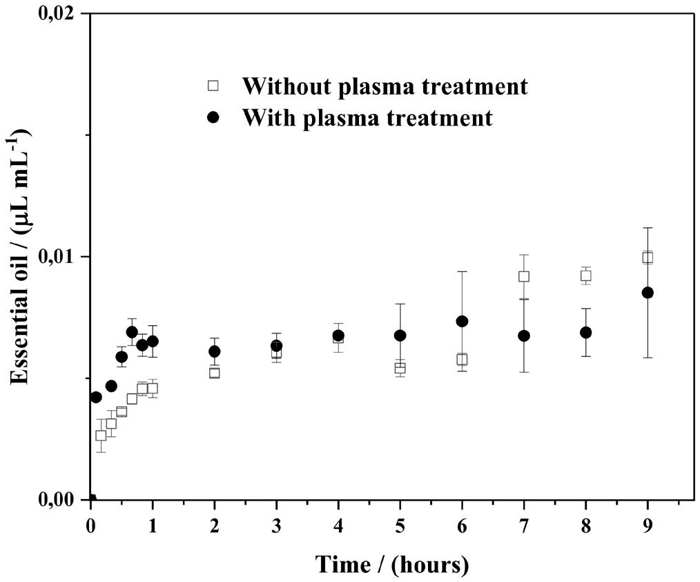
respectively. The greater amount in IM1 is justified by the adsorption of free CEO, around 20% of the total amount, according to the results of EE%. The decrease in the total amount of CEO retained in the textile could be explained by the effect of the vacuum system applied in IM2 and IM3, which can contribute to vaporizing the non-loaded CEO.
The in vitro release assays were performed only for the samples obtained by IM1, since those samples show the highest CEO content. Figure 4 exhibits two release curves from cotton samples impregnated with NPs via immersion for treated and non-treated textiles. Variance analysis shows that Fcrit>Fcalc (p=0.05), so it can be suggested that the plasma surface treatment does not significantly improve the nanoparticles-textile interaction and, consequently, the release profile of CEO, under the studied conditions. For this reason, the non-treated cotton sample was chosen to perform the microbiological test.
The microbiologic test, performed under static conditions, is based on the growth of the microorganism when it comes into close contact with the impregnated sample. On the other hand, the active compound is subjected to mechanisms of transport and diffusion from the textile to the plate, where its activity inhibits growth under and around the textile[35]. The bactericidal activity of the textile against the gram-negative bacteria P. aeruginosa is observed in Figures 5a, 5b, 5c, and 5d, and Figures 5e, 5f, 5g, and 5h, the result of the test performed for the gram-positive bacteria S. aureus. For blank samples, that is, without nanoparticles treatment, the growth of the colonies is observed in the form of fine films, visualized without the use of a microscope on the entire plate, including the underside of the fabric.
The bactericidal activity of cotton fabric treated with NPs loaded with CEO is shown in Figures 5c, 5d, 5g, and 5h, in which the final concentration of the active was about 5.9 ± 0.37 μL cm2 .
According to the standard ABNT NBR 15275, the evaluation is only related to the growth or no growth under de sample material. For example, the growth under the samples
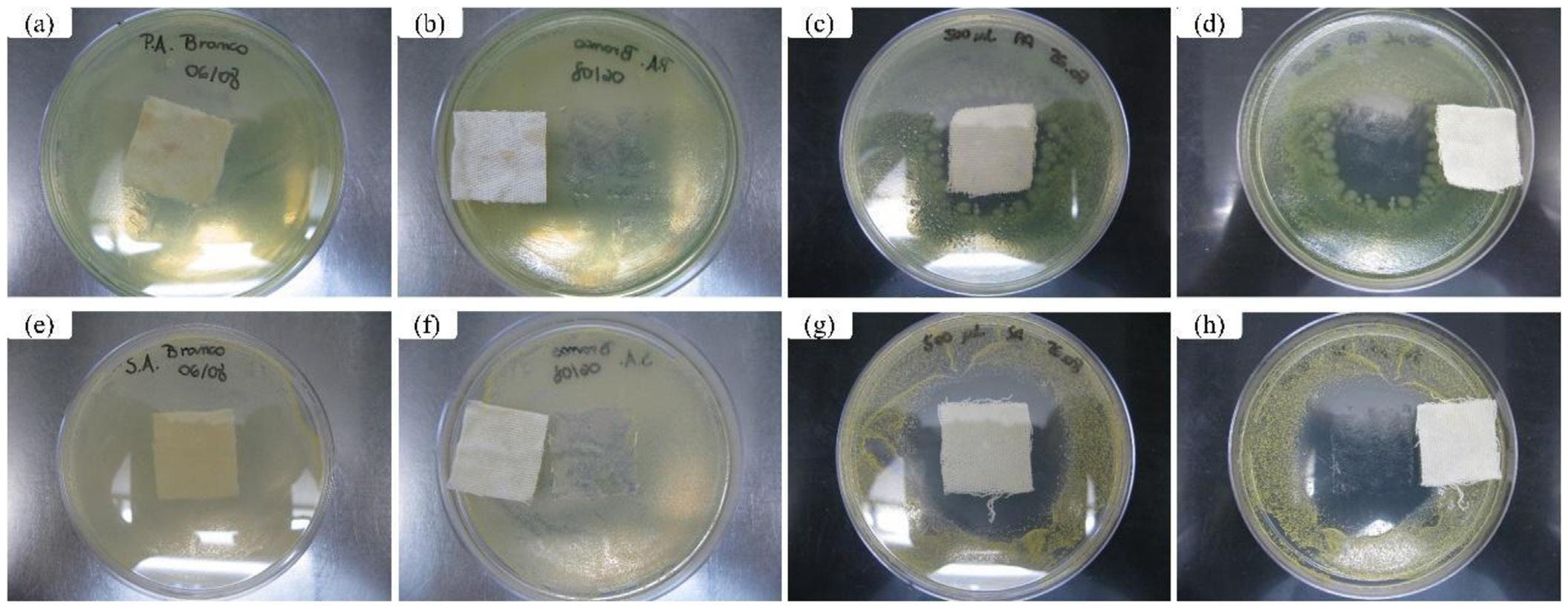
Cotton textile with citronella nanoparticles: Antimicrobial properties and surface functionalization strategies
was observed in Figures 5b and 5f, and in Figures 5d and 5h, there was a growth inhibition. Suppose there is an inhibition zone (halo) around the sample material. In that case, it means that the biocide reagent is soluble in water and that diffusion creates a concentration gradient of the biocide reagent around the sample material. If the halo is greater in the case of a specific bacteria, it means that lower active concentrations are sufficient to inhibit the growth of that organism, compared to another. In this context, the results have proven to be efficient in terms of bacterial resistance for the two organisms in the study.
Similar results were reported by Hidayah et al.[36] , that there is a greater halo of inhibition against S. aureus when compared to P. aeruginosa, once citronella EO has bactericidal characteristics that inhibit the growth of S. aureus biofilm. Lopez-Romero et al.[37] attribute to citronellol and citronellal the bactericidal activity of both gram-positive and gram-negative bacteria. These terpenoids are capable of disrupting the hydrophilic channels in the outer membrane, even of gram-negative bacteria. Rodríguez-Lopez et al.[38] confirm the effect of monoterpenes from essential oils on the permeability of the outer membrane of gram-negative bacteria.
Treating the cotton surface with non-thermal oxygen plasma for 1 or 5 minutes did not significantly improve the adhesion of nanoparticles containing citronella essential oil (CEO). Despite the increase in wettability and chemical and morphological modification of the fibers after treatment, especially with 5 minutes of exposure, the data obtained did not indicate direct benefits in the loading or release of the active ingredient. Among the impregnation methods evaluated, immersion deposition stood out as the most efficient strategy for incorporating CEO. The sample functionalized by this method, without plasma pre-treatment, showed bactericidal activity against S. aureus and P. aeruginosa, with greater efficacy against gram-positive bacteria. The results reinforce the potential of using nanoparticles containing CEO in the antimicrobial functionalization of fabrics and highlight the viability of simple methods such as immersion for application to cellulose substrates.
● Conceptualization – Mariele Paludetto Sanches; Alexandre Luís Parize; Valdir Soldi
● Data curation – Mariele Paludetto Sanches; Rodrigo Henrique Saatkamp; Idejan Padilha Gross; Taís Felix
● Formal analysis – Mariele Paludetto Sanches; Rodrigo Henrique Saatkamp; Idejan Padilha Gross; Taís Felix; Markus Wilimzig
● Funding acquisition – Valdir Soldi; Alexandre Luís Parize.
● Investigation – Mariele Paludetto Sanches; Rodrigo Henrique Saatkamp; Idejan Padilha Gross; Taís Felix; Markus Wilimzig
● Methodology – Mariele Paludetto Sanches; Rodrigo Henrique Saatkamp; Idejan Padilha Gross; Taís Felix; Markus Wilimzig
● Project administration – Alexandre Luís Parize; Valdir Soldi
● Resources – Valdir Soldi; Alexandre Luís Parize; Nito Angelo Debacher
● Software – NA.
● Supervision – Alexandre Luís Parize; Nito Angelo Debacher; Valdir Soldi
● Validation – NA.
● Visualization – Mariele Paludetto Sanches; Rodrigo Henrique Saatkamp
● Writing – original draft – Mariele Paludetto Sanches; Rodrigo Henrique Saatkamp
● Writing – review & editing – Mariele Paludetto Sanches; Rodrigo Henrique Saatkamp; Alexandre Luís Parize
The authors are thankful to Coordenação de Aperfeioçoamento de Pessoal de Nível Superior (CAPES), Conselho Nacional de Desenvolvimento Científico e Tecnológico (CNPq) (Code: 001), and the Foundation for Research and Innovation of the State of Santa Catarina (FAPESC) (Protocol 67811.44.51565.11072024) for providing financial support for this research. Alexandre L. Parize is grateful for his PQ fellowship (process 305112/2022-8) and Laboratório Central de Microscopia Eletrônica (LCME) - UFSC for technical support during electron microscopy work.
1 Tanasa, F., Teaca, C.-A., Nechifor, M., Ignat, M., Duceac, I. A., & Ignat, L. (2023). Highly specialized textiles with antimicrobial functionality-advances and challenges. Textiles, 3(2), 219-245 https://doi.org/10.3390/textiles3020015
2. Gulati, R., Sharma, S., & Sharma, R. K. (2022). Antimicrobial textile: recent developments and functional perspective. Polymer Bulletin, 79(8), 5747-5771 https://doi.org/10.1007/ s00289-021-03826-3 PMid:34276116.
3 Broadhead, R., Craeye, L., & Callewaert, C. (2021). The future of functional clothing for an improved skin and textile microbiome relationship. Microorganisms, 9(6), 1192 https:// doi.org/10.3390/microorganisms9061192 PMid:34073029.
4. Oliveira, C. S. F., & Tavaria, F. K. (2023). The impact of bioactive textiles on human skin microbiota. European Journal of Pharmaceutics and Biopharmaceutics, 188, 66-77 https:// doi.org/10.1016/j.ejpb.2023.05.004 PMid:37182552.
5 Massella, D., Argenziano, M., Ferri, A., Guan, J., Giraud, S., Cavalli, R., Barresi, A. A., & Salaun, F. (2019). Bio-functional textiles: combining pharmaceutical nanocarriers with fibrous materials for innovative dermatological therapies. Pharmaceutics, 11(8), 403 https://doi.org/10.3390/pharmaceutics11080403 PMid:31405229.
6 Repon, M. R., Islam, T., Islam, T., Ghorab, A. E., & Rahman, M. M. (2023). Cleaner pathway for developing bioactive textile materials using natural dyes: a review. Environmental Science and Pollution Research International, 30(17), 48793-48823 https://doi.org/10.1007/s11356-023-26131-0 PMid:36879092.
7 Freitas, A. S., Oliveira, R., Ribeiro, A., & Almeida-Aguiar, C. (2024). Biofunctional textiles: antioxidant and antibacterial finishings of cotton with propolis and honey. International Journal of Molecular Sciences, 25(15), 8034 https://doi. org/10.3390/ijms25158034 PMid:39125604.
8. Shah, M. A., Pirzada, B. M., Price, G., Shibiru, A. L., & Qurashi, A. (2022). Applications of nanotechnology in smart textile industry: a critical review. Journal of Advanced Research, 38, 55-75 https://doi.org/10.1016/j.jare.2022.01.008 PMid:35572402.
9 Kant, R., & Kumar, A. (2022). Review on essential oil extraction from aromatic and medicinal plants: techniques, performance and economic analysis. Sustainable Chemistry and Pharmacy, 30, 100829 https://doi.org/10.1016/j.scp.2022.100829
10 Coimbra, A., Ferreira, S., & Duarte, A. P. (2022). Biological properties of Thymus zygis essential oil with emphasis on antimicrobial activity and food application. Food Chemistry, 393, 133370 https://doi.org/10.1016/j.foodchem.2022.133370 PMid:35667177.
11 Sanches, M. P., Gross, I. P., Saatkamp, R. H., Parize, A. L., & Soldi, V. (2020). Chitosan-sodium alginate polyelectrolyte complex coating Pluronic® F127 nanoparticles. Journal of the Brazilian Chemical Society, 31(4), 803-812 https://doi. org/10.21577/0103-5053.20190244
12 Yan, D., Li, Y., Liu, Y., Li, N., Zhang, X., & Yan, C. (2021). Antimicrobial properties of chitosan and chitosan derivatives in the treatment of enteric infections. Molecules, 26(23), 7136 https://doi.org/10.3390/molecules26237136. PMid:34885715.
13 Li, J., Fu, J., Tian, X., Hua, T., Poon, T., Koo, M., & Chan, W. (2022). Characteristics of chitosan fiber and their effects towards improvement of antibacterial activity. Carbohydrate Polymers, 280, 119031 https://doi.org/10.1016/j.carbpol.2021.119031 PMid:35027133.
14 Fiedler, J. O., Carmona, O. G., Carmona, C. G., Lis, M. J., Plath, A. M. S., Samulewski, R. B., & Bezerra, F. M. (2019). Application of Aloe vera microcapsules in cotton nonwovens to obtain biofunctional textiles. Journal of the Textile Institute, 111(1), 68-74 https://doi.org/10.1080/004 05000.2019.1625607.
15 Tariq, Z., Izhar, F., Gmd, Z., Zulfiqar, A., Malik, M. H., Oneeb, M., & Khan, A. (2022). Fabrication of higly durable functional textiles through microencapsulation of organic citronella oil. Industrial Crops and Products, 190, 115878 https://doi. org/10.1016/j.indcrop.2022.115878
16 Cruz, J., & Fangueiro, R. (2016). Surface modification of natural fibers: a review. Procedia Engineering, 155, 285-288. https://doi.org/10.1016/j.proeng.2016.08.030
17 Kert, M., Tavcer, P. F., Hladnik, A., Spasić, K., Puač, N., Petrović, Z. L., & Gorjanc, M. (2021). Application of fragrance microcapsules onto cotton fabric after treatment with oxygen and nitrogen plasma. Coatings, 11(10), 1181 https://doi. org/10.3390/coatings11101181
18. Zahid, M., Mazzon, G., Athanassiou, A., & Bayer, I. S. (2019). Environmentally benign non-wettable textile treatments: a review of recent state-of-the-art. Advances in Colloid and Interface Science, 270, 216-250 https://doi.org/10.1016/j. cis.2019.06.001. PMid:31277037.
19 Ssekasamba, H., Tebyetekerwa, M., Haodong, C., Balilonda, A., Ssegwanyi, S., Gao, Q., & Xiaoliang, T. (2024). Review of plasma surface engineering technology toward sustainable textile materials. Materials Circular Economy, 6(1), 27 https://doi.org/10.1007/s42824-024-00114-z
20 Naebe, M., Li, Q., Onur, A., & Denning, R. (2016). Investigation of chitosan adsorption onto cotton fabric with atmospheric helium/oxygen plasma pre-treatment. Cellulose , 23 (3), 2129-2142 https://doi.org/10.1007/s10570-016-0915-0
21 Felix, T., Cassini, F. A., Benetoli, L. O. B., Dotto, M. E. R., & Debacher, N. A. (2017). Morphological study of Polymer surfaces exposed to non-thermal plasma based on contact angle and the use of scaling laws. Applied Surface Science, 403, 57-61 https://doi.org/10.1016/j.apsusc.2017.01.036
22 Kulthong , K. , Srisung , S. , Boonpavanitchakul , K. , Kangwansupamonkon, W., & Maniratanachote, R. (2010). Determination of silver nanoparticle release from antibacterial fabrics into artificial sweat. Particle and Fibre Toxicology, 7(1), 8 https://doi.org/10.1186/1743-8977-7-8 PMid:20359338.
23 Ali, Z., Talpur, F. N., Afridi, H. I., Ahmed, F., Brohi, N. A., & Abbasi, H. (2025). Analytical approaches and advancement in the analysis of natural and synthetic fiber: a comprehensive review. Spectrochimica Acta. Part A, Molecular and Biomolecular Spectroscopy , 326 , 125164 https://doi.org/10.1016/j. saa.2024.125164. PMid:39332174.
24 Takahashi, G., & Akashi, H. (2011). Various kinds of streamers in atmospheric pressure oxygen dielectric barrier discharge. IEEE Transactions on Plasma Science, 39(11), 2234-2235. https://doi.org/10.1109/TPS.2011.2160564
25 Kan, C.-W., & Man, W.-S. (2018). Surface characterization of atmospheric pressure plasma-treated cotton fabric -effect of operation parameters. Polymers, 10(3), 250 https://doi. org/10.3390/polym10030250 PMid:30966285.
26 Pandiyaraj, K. N., & Selvarajan, V. (2008). Non-thermal plasma treatment for hydrophilicity improvement of grey cotton fabrics. Journal of Materials Processing Technology, 199(1-3), 130-139 https://doi.org/10.1016/j.jmatprotec.2007.07.046
27 Vestena, M., Gross, I. P., Muller, C. M. O., & Pires, A. T. N. (2016). Isolation of whiskers from natural sources and their dispersed in a non-aqueous medium. Polímeros: Ciência e Tecnologia, 26(4), 327-335. https://doi.org/10.1590/0104-1428.2367.
28 Meyabadi, T. F., Dadashian, F., Sadeghi, G. M. M., & Asl, H. E. Z. (2014). Spherical cellulose nanoparticles prepatation from waste cotton using a green method. Powder Technology, 261, 232-240 https://doi.org/10.1016/j.powtec.2014.04.039
29 Li, M., He, B., Chen, Y., & Zhao, L. (2021). Physicochemical properties of nanocellulose isolated from cotton stalk waste. ACS Omega, 6(39), 25162-25169 https://doi.org/10.1021/ acsomega.1c02568 PMid:34632175.
30 Hossain, M. M., Herrmann, A. S., & Hegemann, D. (2006). Plasma hydrophilization effect on different textile structures. Plasma Processes and Polymers, 3(3), 299-307 https://doi. org/10.1002/ppap.200500152
31 Man, W. S., Kan, C. W., & Ng, S. P. (2014). The use of atmospheric pressure plasma treatment on enhancing the pigment application to cotton fabric. Vacuum, 99, 7-11 https://doi.org/10.1016/j. vacuum.2013.04.018.
32 Sarma, B., Sarma, A., & Rani, K. V. (2018). Plasma treatment on cotton fabrics to enhance the adhesion of reduced graphene oxide for electro-conductive properties. Diamond and Related Materials, 84, 77-85 https://doi.org/10.1016/j.diamond.2018.03.009
33 Prysiazhnyi, V., Kramar, A., Dojcinovic, B., Zekic, A., Obradovic, B. M., Kuraica, M. M., & Kostic, M. (2013). Silver incorporation on viscose and cotton fibers after air, nitrogen and oxygen DBD plasma pretreatment. Cellulose, 20(1), 315-325 https://doi.org/10.1007/s10570-012-9817-y
34 Li, W.-R., Shi, Q.-S., Ouyang, Y.-S., Chen, Y.-B., & Duan, S.-S. (2013). Antifungal effects of citronella oil against Aspergillus niger ATCC 16404. Applied Microbiology and Biotechnology, 97(16), 7483-7492 https://doi.org/10.1007/s00253-012-4460-y. PMid:23081773.
35 López, A., Lis, M. J., Bezerra, F. M., Vilaseca, M., Vallés, B., Prieto, R., & Simó, M. (2019). Production and evaluation of antimicrobial microcapsules with essential oils using complex coacervation. Journal of Biomedical Science and Engineering, 12(8), 377-390 https://doi.org/10.4236/jbise.2019.128029
Sanches, M. P., Saatkamp, R. H., Gross, I. P., Felix, T., Debacher, N. A., Wilimzig, M., Parize, A. L., & Soldi, V. Polímeros, 36(1), e20260010, 2026
Cotton textile with citronella nanoparticles: Antimicrobial properties and surface functionalization strategies
36 Hidayah, A. N., Wasito, E. B., Debora, K., Basori, A., Isnaeni, I., & Utomo, B. (2019). Correlation between the bacteriostatic and bactericide effect with antibiofilm and anticolony spreading from Javanese Citronella oil on methicillin-resistant Staphylococcus aureus (MRSA). Folia Medica Indonesiana, 55(1), 1-9 https://doi.org/10.20473/fmi.v55i1.12542
37 Lopez-Romero, J. C., González-Ríos, H., Borges, A., & Simões, M. (2015). Antibacterial effects and mode of action os selected essential oils components against Escherichia coli and Staphylococcus aureus. Evidence-Based Complementary and Alternative Medicine: eCAM , 2015 ( 1 ), 795435 https://doi.org/10.1155/2015/795435 PMid:26221178.
38 Rodríguez-Lopez, M. I., Mercader-Ros, M. T., Pellicer, J. A., Gómez-López, V. M., Martínez-Romero, D., Núñez-Delicado, E., & Gabaldón, J. A. (2020). Evaluation of monoterpenecyclodextrin complexes as bacterial growth effective hurdles. Food Control , 108 , 106814 . https://doi.org/10.1016/j. foodcont.2019.106814
Received: Aug. 02, 2025
Revised: Nov. 04, 2025
Accepted: Nov. 23, 2025
Editor-in-Chief: Sebastião V. Canevarolo
Supplementary material accompanies this paper.
Table S1. Summary of cotton sample compositions by X-ray photoelectron spectroscopy.
Figure S1. Non-thermal plasma reactor scheme: a) power supply, b) electrodes, c) dielectric barrier, d) sample, e) gas inlet, and f) vacuum pump.
Figure S2. Scheme of impregnation methods: (a) spray I and (b) spray II. Legend: a) compressor air, a’) N2 compressed gas, b) airbrush, b’) Springer with a needle, c) NPs spray, d) cotton textile support, e) vacuum pump, f) zoom of cotton textile fixed on support, and g) dripper.
Figure S3. Contact angle analysis of an untreated textile with water.
Figure S4. Infrared spectra curves of cotton fiber untreated and NTP treatment.
Figure S5. Cot-n (a), Cot-1 (b) and (c), and Cot-5 (d).
Figure S6. Calibration curve of citronella essential oil in simulated sweat fluid, pH=4.3.
This material is available as part of the online article from https://doi.org/10.1590/0104-1428.20250068
Sanches, M. P., Saatkamp, R. H., Gross, I. P., Felix, T., Debacher, N. A., Wilimzig, M., Parize, A. L., & Soldi, V. Polímeros, 36(1), e20260010,
Nivaldo Ramos Júnior1 , Ana Paula Testa Pezzin1 and Denise Abatti Kasper Silva1*
1Laboratório de Materiais, Programa de Pós-graduação em Engenharia de Processos, Universidade da Região de Joinville – UNIVILLE, Joinville, SC, Brasil *denise.abatti@univille.br
Obstract
Replacing petroleum-based packaging with biodegradable materials encourages the development of polymers from renewable sources such as sodium alginate, which is biodegradable and abundant in brown algae. The goal of this study was to promote sustainable seedling packaging practices by producing sodium alginate films enriched with urea and glycerol as plasticizers, which were then cross-linked with calcium, fumaric acid, or adipic acid. In this study, both 27 wt% urea and 10 wt% glycerol was used, and the alginate films were prepared by casting with 3 or 10 wt% cross-linker. Thermogravimetric analysis showed that films containing urea exhibited greater thermal stability. FT-IR spectroscopy revealed the formation of partial cross-links between alginate and the cross-linkers, which improved the mechanical and viscoelastic properties. Films cross-linked with calcium ions suggesting that urea does not significantly alter alginate, but contributes to film rigidity, which limits their application for the intended purpose.
Keywords: biodegradable polymer, sodium alginate, cross-linkers.
Data Ovailability: All data supporting the findings of this study are included in this article and its supplementary materials.
How to cite: Ramos Júnior, N., Pezzin A. P. T., & Silva, D. A. K. (2026). Exploring urea and cross-linkers in alginate films for agricultural seedlings. Polímeros: Ciência e Tecnologia, 36(1), e20260011. https://doi.org/10.1590/0104-1428.20250053
One of the sectors that has increasingly used plastic inputs is agriculture, with an estimated consumption of 12.5 million tons[1]. Among the products that cause soil contamination is the use of plastic bags for growing agricultural seedlings. From this standpoint, substituting this type of packaging for a biodegradable material that ensures seedling transfer may be a plausible alternative.
Alginate, a naturally derived polysaccharide, has garnered significant attention in various fields due to its unique properties and versatile applications, which include 3D bioprinting, drug delivery systems, and sorptive properties[2], producing wound dressings and tissue engineering scaffolds, owing to its biocompatibility, biodegradability, and ability to form hydrogels [ 3 ] The degradation of sodium alginate primarily yields oligosaccharides and monosaccharides, which are nontoxic and can be absorbed by microorganisms without harming the environment. These environmentally friendly features of sodium alginate make it a choice for application in the biomedical, pharmaceutical, cosmetics, textiles, and food science industries[3]. These sustainable characteristics make the alginate biopolymer suitable for environmental remediation, such as the adsorption of dyes and metals[4,5] and the controlled release of fertilizers[6] When modified[7] or enriched with components such as urea, alginate can improve its mechanical properties and
control the release of essential nutrients, such as nitrogen and carbon into the soil[7]. Additionally, the dispersion of nutrients in alginate films can reduce losses from volatilization and leaching[8-11]
On the other hand, researchers have explored the use of carboxylic acids[12-14] for polysaccharide crosslinking; the primary example is citric acid (CA)[15]. Films with this composition are important for exploring the diffusion process, both for delivering substances and for retaining water. The hypothesis was to verify whether alginate films could be partially cross-linked using other organic acids, such as adipic[16,17] and fumaric[8,18] acids. This study seeks to develop urea-enriched alginate films and evaluate the impact of different cross-linking agents on their physical, thermal, mechanical, and biodegradation properties.
2.1
Sodium alginate (viscosity: 15-25 cycles per second, 1% in water) and Fumaric acid (99% T) were purchased from Sigma Aldrich Co., Ltd. Adipic acid (99.5% T) was obtained from Êxodo científica, calcium chloride (CaCl2) was supplied by Labsynth Ltd.. Urea was obtained from Tianjin Kaitong Chemical Reagent Co., Ltd. Glycerol was purchased from Sigma Aldridge Co., Ltd.
Sodium alginate (6 g) was dissolved in 200 mL type 1 ultrapure water (Milli-Q) containing urea, 27% w/w, and this mixture was heated under reflux at 50 °C for 3 h[5]. The AlgUr sample was collected, frozen, lyophilized, and stored in a desiccator until films were produced.
A mass of 2.5 g of polymer was dissolved in 125 mL of deionized water under moderate magnetic stirring at a temperature of 45 ± 5 °C for 1 h. After complete dissolution, 0.250 g glycerol was added, and the mixture was stirred at 50 °C. The homogeneous solution was divided into two containers (20 × 20 × 5 cm) of 60 mL each and then placed in an oven at 80 °C for 6 h. After drying, the films were stored in a desiccator for 48 h. Two calcium chloride (CaCl2) solutions of 3% and 10% (w/w) in 300 mL of distilled water were prepared for cross-linking. The films were immersed in these solutions for 10 min and then washed with distilled water to prevent the accumulation of crystals on the film surface. The films were then placed in an oven at 30 °C for 6 h and stored in a desiccator for 48 h until further characterization. These films were identified as AlgGlCa 3%, AlgGlCa 10%, AlgUrGlCa 3%, and AlgUrGlCa 10%, respectively.
After complete alginate and glycerol dissolution, the solution was divided into two beakers to prepare solutions containing 3 and 10% fumaric acid (Fu) or adipic acid (Ad). For cross-linking with acids, the procedure followed the protocol described previously[19]. The entire process was performed under stirring at 50 °C. The solutions were poured into the containers and placed in an oven at 80 °C for 8 h to promote cross-linking. Subsequently, the films were removed from the molds and stored for characterization, identified as AlgGlFu 3%, AlgGlFu 10%, AlgUrGlFu 3%, AlgUrGlFu 10% and with as AlgGlAd 3%, AlgGlAd 10%, AlgUrGlAd 3%, AlgUrGlAd 10%).
2.3 Preliminary characterization of alginate films, alginate with urea, and pure components
In this phase, the Fourier Transform Infrared Spectroscopy (FTIR) technique was used to identify the effects of each component on the spectral profile of alginate. Using a Perkin Elmer Frontier equipment with an ATR accessory, 32 scans were performed in the range of 4000 to 650 cm−1, with a resolution of 4 cm−1
In addition, thermogravimetric analysis (TGA) was performed. The samples were heated from 25 °C to 600 °C at 10 °C/min under an inert atmosphere (N2) using TGA-Q50 equipment (TA Instruments). TG/DTG curves were obtained using TA Universal Analysis software.
2.4 Characterization of alginate-based and modified alginate-based films
The films produced were characterized by FTIR and TGA under the same conditions described in Section 2.3. DSC was used to characterize the samples. DSC curves were obtained under a dynamic nitrogen atmosphere (50 mL min−1) using hermetically sealed aluminum crucibles containing 4-5 mg of
the sample. The temperature range used was 25-400 °C, at a heating rate of 10 °C min−1, using TA Instruments DSC Q20 equipment. The results were analyzed using TA Universal Analysis software, allowing the verification of the effect of polymer modifications on the glass transition temperature (Tg) of the films. Mechanical characterization of the films was performed on a NETZSCH DMA dynamic-mechanical analyzer, model 980, at a frequency of 2.5 Hz in the temperature range of −90 to 130 °C. The test specimens were obtained as films with dimensions of 30 × 5 × 1 mm. Nitrogen gas was used at a heating rate of 2 °C·min−1
To evaluate the biodegradation of the films, the soil was previously prepared in agreement with ASTM G160-98, then was placed in 1 L beaker cups, approximately 15 cm high, and kept at 30 °C with relative humidity of 85-95%. After, the films were cut to the dimensions 5 cm x 5 cm, dried in an oven with air circulation at 20 °C for 24 h, weighed, inserted into nylon casings with a mesh that allowed exchange with the soil, and then buried in a beaker. This test was performed in duplicate. The effect of the film’s degradation was monitored over 42 days. The samples were removed every 7 days, carefully cleaned them with a soft brush and visually inspected.
3.1
In the first step, the pure alginate film was characterized to demonstrate the effect of urea and glycerol on the films (Figure 1).
The alginate spectrum was typical, presenting a band between 3600 and 3100 cm−1, characteristic of O-H stretching, bands at 1590 cm−1 and 1410 cm−1 attributed to the asymmetric and symmetric stretching of the carboxylate group (O-C-O), respectively. Furthermore, in the region between 1330 and 1000 cm−1, shoulders and peaks characteristic of the pyranose group were observed at 1297 cm−1, associated with the angular deformation of C-C-H and O-C-H. The peaks at 1080 and 1020 cm−1 were associated with C-O and C-C stretching, respectively. The band at 815 cm−1 was related to mannuronic acid residues[20,21]. For urea, two bands (doublets) between 3500 and 3250 cm−1 refer to the asymmetric and symmetric N-H stretching of the primary amine, respectively[22]. The band at 1675 cm−1 was attributed to carbonyl (C=O) and identified as amide band I, followed by the band at 1600 cm−1 attributed to the angular deformation of NH2, the bands at 1458 cm−1 related to the stretching of the C-N bond, and the band at 1150 cm−1 attributed to the rocking deformation of primary amines[23,24]. The glycerol spectrum showed a broad absorption band at 3300 cm−1, characteristic of O-H stretching from the alcohol groups. The bands at 2937 and 2878 cm−1 were attributed to the stretching mode of the C-H bonds, including a band at 1660 cm−1 corresponds to the angular deformation (bending) of the -OH group and one band at 1417 cm−1 may be related to the angular deformation of -CH2. In addition, the 1110 and 1035 cm−1 absorptions were attributed to the C-O stretching of secondary and primary alcohols, respectively[25]
Exploring urea and cross-linkers in alginate films for agricultural seedlings
The physical characteristics of the films were also distinct, with those of AlgUr being more flexible than Alg. For the control film (Alg10%G), preserved the main band of alginate and glycerol, the band observed at 1040 cm−1 can be attributed to C-O stretching groups[26], including the asymmetric and symmetric stretching vibrations of COOat wavenumbers of 1598 and 1411 cm−1, respectively[27,28].
The alginate film with urea (AlgUr) is the sum of these two components, while alginate-urea films with glycerol (AlgUr 10%G) show overlap of mainly bands as OH and NH stretching bands around 3300 cm−1, a slight shift to lower wavenumbers for the amide I band at 1654 cm−1 and NH2 stretching observed at 1596 cm−1
Those generated via ionic cross-linking (Ca2+) are shown in Figure 2
The alginate-based films (AlgGli) presented the bands predicted and already described for the alginate-glycerol film. A close look at the band corresponding to the stretching of the carboxylate ion (gray line) revealed a slight shift to lower wavenumbers from 1600 cm−1 to 1590 cm−1. This change can be associated with the interaction of the regular homopolymer chain with sodium ions and the change in density, radius, and atomic mass when Ca2+ replaces Na+ [29]. Furthermore, there was a decrease in the intensity of the characteristic bands of alginate, such as the -OH stretching band around 3300 cm−1 and the asymmetric and symmetric stretching
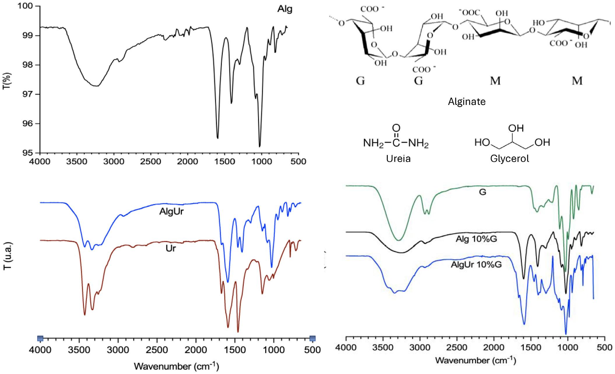
1. FT-IR spectra of alginate-based films: alginate (Alg), alginate with urea (AlgUr), pure urea (Ur), and glycerol (G), and their respective structural forms. Alginate being composed of blocks of α-L-guluronic acid (G block) and β-D-mannuronic acid (M block).
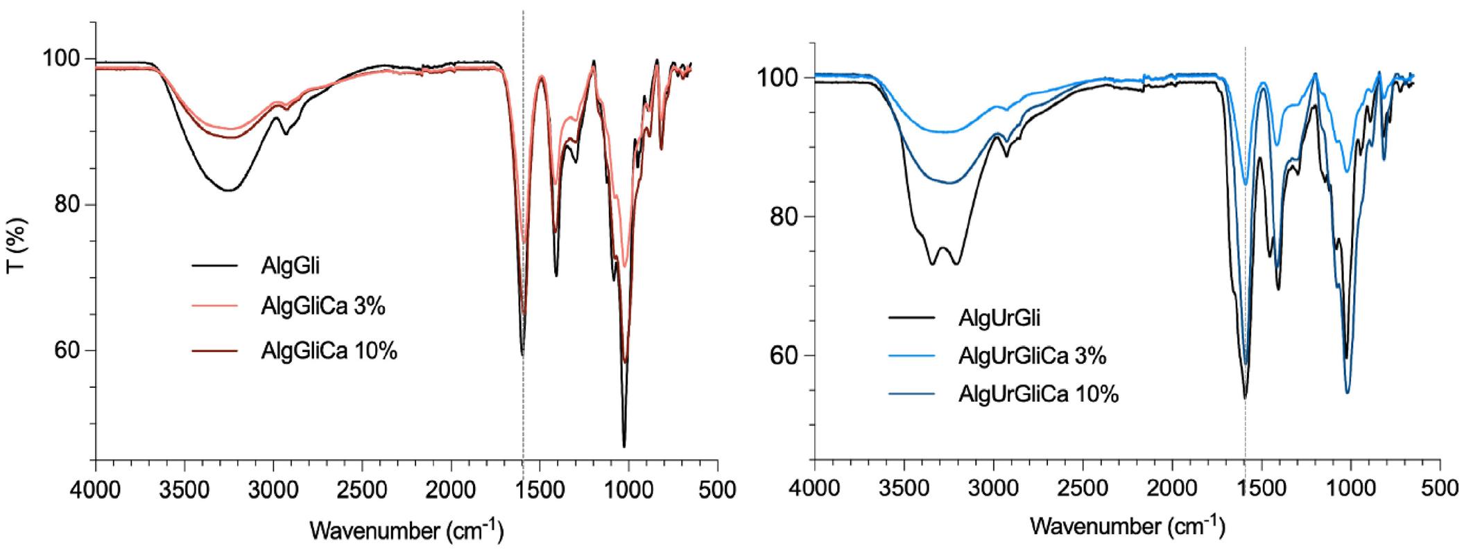
2. FTIR spectra of alginate-based films (AlgGli) and urea-modified alginate (AlgUrGli) containing 10% glycerol and cross-linked with 3% or 10% (w/w) Ca2+ ions.
bands of the carboxylate anion around 1600 and 1400 cm−1, respectively, suggesting that there was an interaction between the hydroxyl and carboxylate groups of alginate and Ca2+ ions in the formation of the chelating structure.
The AlgUrGl sample presented overlapping bands for the O-H/N-H and carbonyl groups, as discussed above. However, bands related to the presence of urea were not evident in the samples after being submerged in solutions containing Ca2+ ions. Considering the similarities observed between the spectra of the AlgUrGli samples and the AlgGli samples, suggesting that at least part of the urea was removed from the films, which implies a reduction in the nitrogen content of the sample. However, although the shift of the carboxyl band (gray dotted line) was discrete, there was a reduction in the intensity of this band, it was attributed to the hydroxyl group, indicating the interaction of Ca2+ ions.
Figure 3 shows a change in the 1750-1730 cm−1 region, indicative of cross-linking, in the fumaric and adipic acid samples through the formation of ester bonds. This discrete
modification was also observed when carboxymethyl cellulose was cross-linked with citric acid[30]. In the case of the AlgGliFu and AlgGliAd 3% samples, there was also a reduction in the OH bands (3300 cm−1), and that related to the C-OH stretching at 1410 cm−1, which reinforces the hypothesis of partial cross-linking of these films with these acids.
Analogous to the sample without urea, the spectra of AlgGliUr samples with 3 and 10% fumaric and adipic acids were similar. There was also a subtle change in the region 1750-1730 cm−1, indicative of cross-linking through the formation of ester bonds, demonstrating that the acids acted as cross-linkers, at least partially.
Figure 4 illustrates the thermal degradation profiles of the films cross-linked with calcium in the absence and presence of urea, and the data are summarized in Table 1
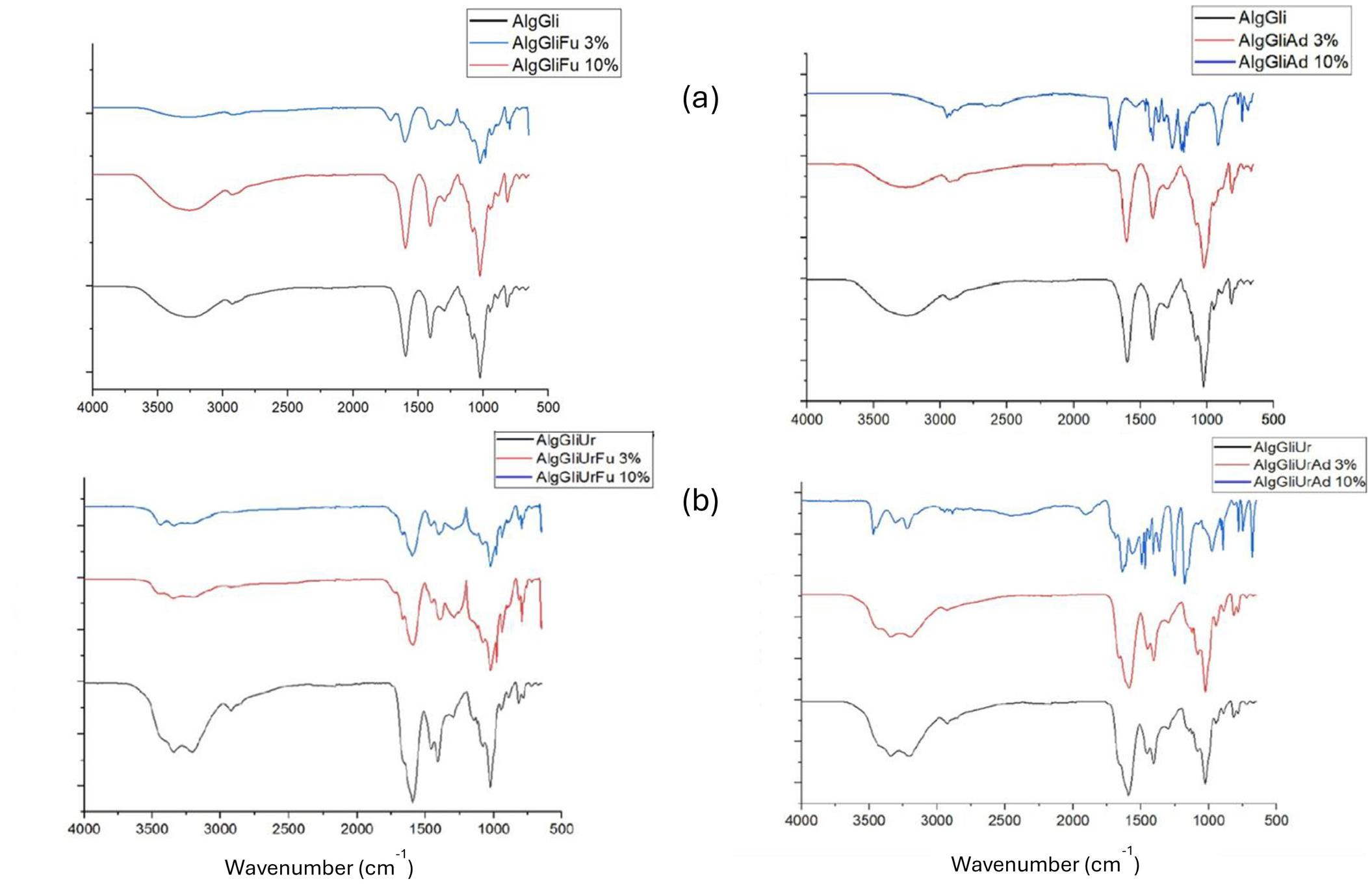
Figure 3. FTIR spectra of films (a) based on alginate (AlgGli), fumaric acid (AlgGliFu), and adipic acid (AlgGliAd), and (b) based on alginate urea (AlgGliUr), fumaric acid (AlgGliUrFu), and adipic acid (AlgGliUrAd) containing 10% glycerol and cross-linked with 3% or 10% (w/w) of acid.
Table 1. Data obtained from TG/DTG curves of urea-modified and unmodified films cross-linked with 3% and 10% w/w of calcium.
Exploring urea and cross-linkers in alginate films for agricultural seedlings
At peak1, more precisely between 20 and 150 °C, dehydration of sodium alginate occurred[31]. The mass loss was similar for all samples in this range, with AlgGliCa 3% showing the highest loss and AlgGliCa 10% the lowest. Film degradation starts at 180 °C and in peak2, the degradation of glycerol was observed, and mass loss occurred between 200 and 249 °C[32], with a degradation peak at 213 °C. In peak 2 of AlgGliCa 3%, mass loss was observed at 215 °C. In peak3 of AlgGliCa 10%, cross-linking of calcium with sodium alginate was observed. The residue is similar.
The effects of fumaric acid and adipic acid contents on the thermal degradation profile of the alginate films are shown in Figure 5, and the results are summarized in Table 2
The 3% and 10% AlgGliAd films present Tpeak1 around 212-215 °C, indicating the occurrence of thermal decomposition reactions of glycerol with a mass loss of approximately 17%. The subsequent mass loss of approximately 37-38% may be associated with the decomposition of the organic components of the film, such as alginate, glycerol, and reaction products of carboxylic acids. Between 220 and 260 °C, degradation of the carboxyl group of sodium alginate occurs with the release of CO2[33]. After the decomposition of the films, the residues were 45-46%, indicating the presence of nonvolatile materials or reaction products[32].
The AlgGliFu 3% and 10% films also presented peaks (Tpeak1) between 213 °C and 217 °C, indicating thermal
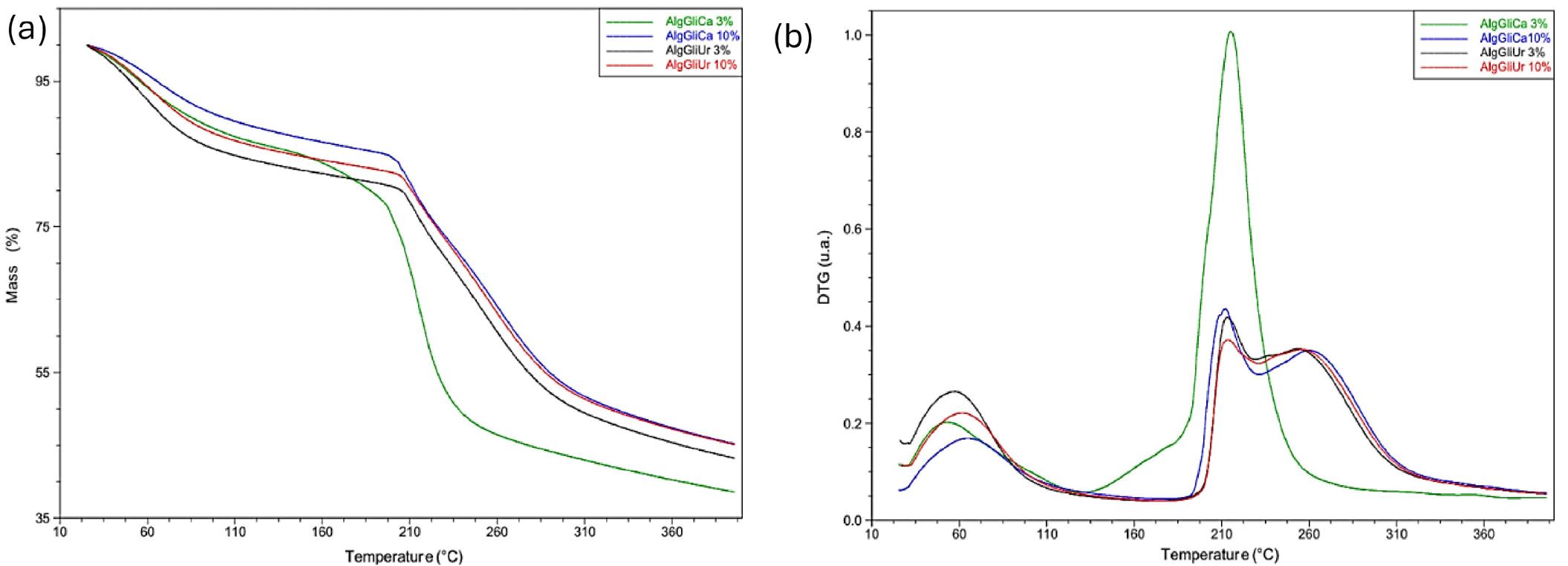
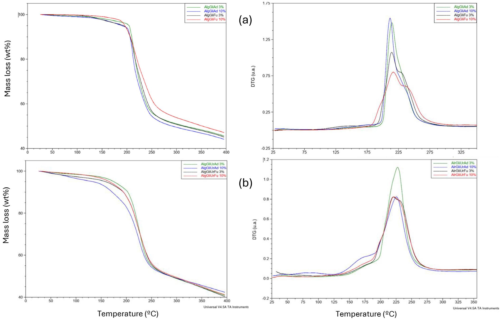
Júnior, N., Pezzin A. P. T., & Silva, D. A. K.
decomposition reactions of glycerol, although at slightly lower temperatures than those containing adipic acid. A more complex film composition or the occurrence of multiple reactions during decomposition are the reasons for the presence of multiple stages of mass loss. The peaks observed at 225-231 °C may be associated with phase transitions or additional decomposition reactions occurring during the heating of the films, as indicated for films containing alginic acid[26]. The presence of peaks in the formulations with fumaric acid suggests differences in the decomposition kinetics or nature of the reactions compared to the films cross-linked with adipic acid.
The effects of acids on the thermal degradation of urea-containing films demonstrated the presence of two distinct stages of mass loss indicates that the decomposition of the films occurred in stages. The first one is generally associated with the loss of moisture or low-molecular-weight volatiles, whereas the second stage is related to the thermal degradation of the polymeric components. The cross-linker concentrations (3% and 10%) did not appear to significantly affect the temperatures at which mass losses began, indicating that the variation in the amount of adipic acid or fumaric
acid did not substantially influence the thermal properties of the films in this specific concentration range.
The absence of peaks at higher temperatures indicates that the thermal decomposition of the films cross-linked with adipic and fumaric acids results in mass loss 2 of approximately 28-29% for adipic acid and 34-35% for fumaric acid. The residue remaining after the decomposition of the films ranged from 40 to 42%. The presence of residues evidences the presence of non-volatile components or reaction products in the sample, and it appeared to be consistent between the different formulations, suggesting that the variation in the adipic acid or fumaric acid concentration did not significantly affect residue formation.
The DSC curves of the films of alginate and alginate-urea with glycerol cross-linked with calcium are presented in Figure 6, and the endothermic temperature (Tendo) and exothermic temperature (Texo) data are presented in Table 3
The curves of the AlgGli and AlgGliUr samples showed broad endothermic peaks at 94 °C and 99 °C, respectively,
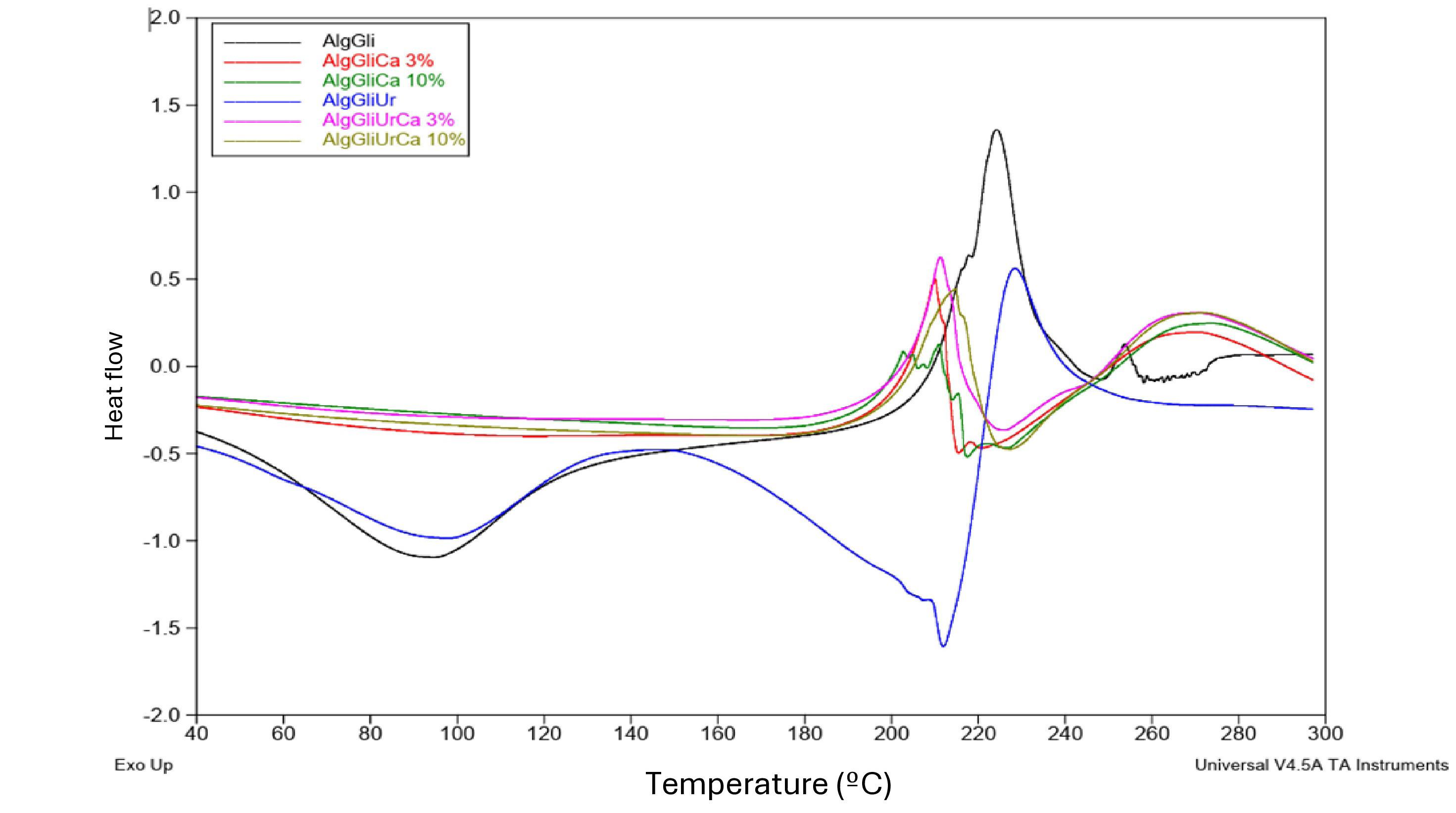
Exploring urea and cross-linkers in alginate films for agricultural seedlings
attributed to the dehydration process of the films[20]. At the molecular level, the presence of Ca2+ ions is considered an obstacle to the rotation (movement) of alginate chains, reducing mobility and, consequently, the ability of the film to elongate[34]. The AlgGliUr sample exhibited a second endothermic event at 212 °C, which can be attributed to the presence of urea[30]
The films cross-linked with calcium (AlgGliCa 3% or 10%) did not exhibit an endothermic peak. However, two exothermic peaks were observed at 210 and 270 °C for the sample with 3% cross-linker and at 211 and 273 °C for the sample with 10%, respectively. The absence of an endothermic peak is explained by the addition of a cross-linker to the film because it causes the union of the chains that are linked by covalent bonds. Therefore, the
cross-linked compounds only undergo degradation at high temperatures, so the percentage of cross-linker does not affect the degradation temperatures of the samples[18]. The 3% and 10% AlgGliUrCa films exhibited the same behavior as the AlgGliCa films. The exothermic peaks for these films were 211 and 269 °C with 3% cross-linker and 215 and 271 °C with 10% cross-linker, respectively. It corroborates with FTIR results that part of the urea was removed from the films during the Ca2+ crosslinking.
The results for the alginate films cross-linked with adipic acid and fumaric acid are presented in Figure 7 and Table 4.
The Tendo1 of the AlgGliAd 3% film was relatively low, registering 67 °C, and may indicate a phase transition or molecular rearrangement associated with the plasticization of sodium alginate with glycerol[35]. Tendo2 at 178 °C shows
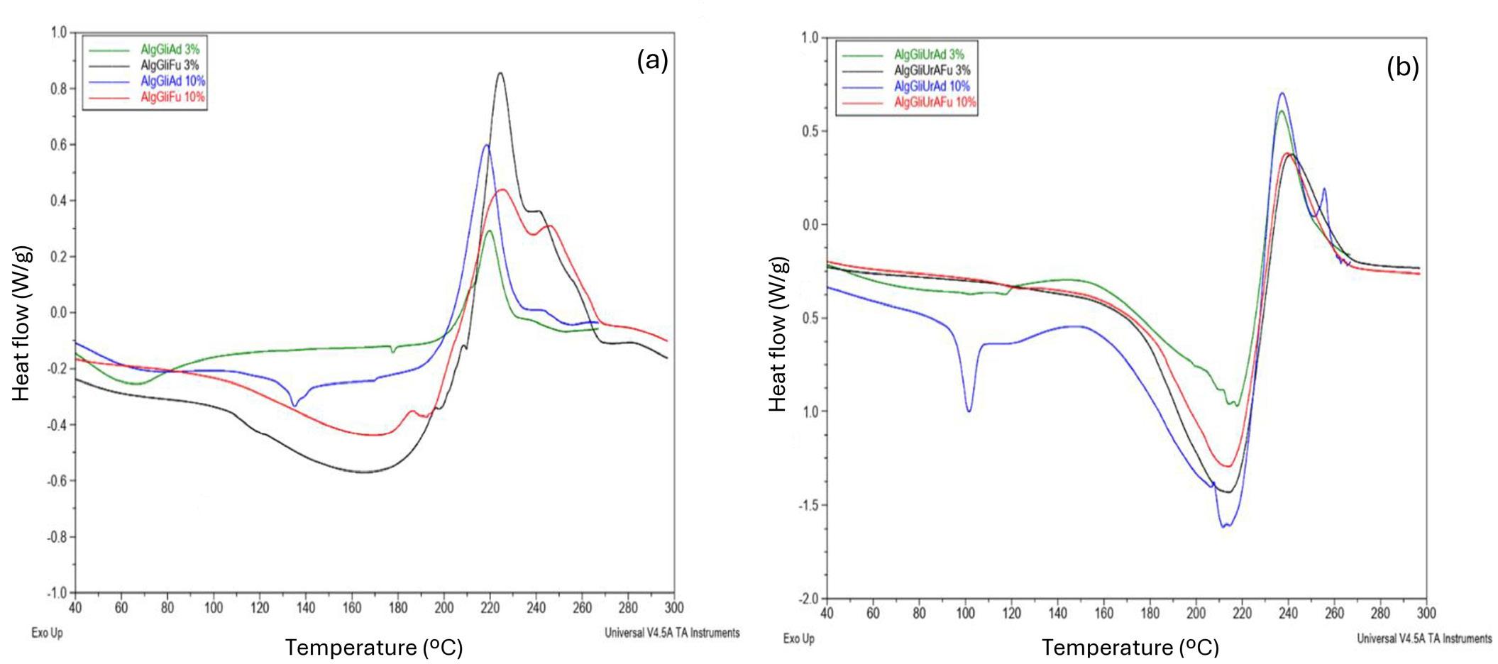
a second thermal transition related to the melting processes or thermal decomposition of components in the film, while Texo1, which was determined to be 220 °C, designates the end of the first thermal transition. For the AlgGliFu 3% film, Tendo1 was 135 °C, a different thermal transition from that observed in AlgGliAd 3%, suggesting variations in the structure or molecular interactions due to fumaric acid as a cross-linker and Texo1 at 220 °C marks the end of the thermal transition. The Tendo1 of the AlgGliAd 10% film was higher than that of AlgGliAd 3%, suggesting a change in the structure of the material due to the increase in the amount of adipic acid as a cross-linker.
The AlgGliUrAd 3%, showed a Tendo1 at 118 °C, and the Tendo2 value was 218 °C, indicating a potential phase transition or crystallization[35] and a second thermal transition that may be related to the melting or thermal decomposition of some components, respectively. While Texo1 was measured at 237 °C, indicating completion of the first thermal transition. The Tendo1 value for AlgGliUrFu 3% was significantly higher than that of AlgGliUrAd 3%, attributed to a different thermal transition, attributed to variations in composition or molecular interactions and, Texo1, measured at 240 °C, can be related to the completion of the thermal transition. Texo1 for AlgGliUrAd 10% films was the lowest among all formulations, registering 101 °C corresponding a change in the structure or composition of the material, possibly owing to an increase in the amount of adipic acid as a cross-linker. Tendo2 showed a wide temperature range, from 215 to 250 °C, and with Texo1 and Texo2 indicate completion of these transitions. The Tendo1 of AlgGliUrFu 10% was similar to that of AlgGliUrAd 10%, meaning that the formulations with 10% cross-linkers shared some thermal properties despite the differences in cross-linkers.
The DMA curves of the storage modulus (E’) vs. temperature for the alginate and alginate films with fumaric acid or adipic acid permitted estimate the storage modulus and Tan δ values for films at 30 °C (Table 5). For the alginate-urea films urea and those cross-linked with calcium, the results were not possible due to their low tensile strength, indicating more rigid films. It is known that elongation decreased after cross-linking the alginate films with calcium[12]. Once the storage modulus refers to the ability of a material to store energy and deform in phase with the applied stress.
Cross-linking with adipic acid or fumaric acid resulted in a decrease in the stiffness of the films except to the AlgGliFu 3% film that presented the second highest E’ value, indicating greater stiffness or elastic energy storage capacity compared to the other films. Adding 3% adipic acid (AlgGliAd 3%) resulted in a 48% decrease in the elastic modulus, while the Tan δ increased, suggesting a greater
energy dissipation capacity and a tendency toward more viscoelastic behavior. This decrease in the elastic modulus can be attributed to the formation of additional cross-links between the alginate polymer chains caused by the adipic acid. Conversely, increasing the adipic acid concentration to 10% (AlgGliAd 10%) resulted in an even more pronounced decrease in elastic modulus, accompanied by a slight decline in the Tan δ compared to the 3% formulation. Meaning that more intense cross-linking has a stronger influence on the mechanical properties of the film, although the energy dissipation capacity remained relatively stable.
The AlgGliFu 3% formulation presented an elastic modulus comparable to AlgGli but with a slightly lower Tan δ, indicating a lower energy dissipation capacity. However, the AlgGliFu 10% formulation showed a significant reduction in the elastic modulus, accompanied by a considerable increase in Tan δ, suggesting a transition to more viscoelastic behavior and a greater energy dissipation capacity. This can be attributed to the formation of additional cross-links induced by fumaric acid, which has a more pronounced impact on the mechanical properties of the film. These films exhibit an elastic response, deformation, and an increase in their storage modulus with increasing temperature.
When analyzing a typical DMA result, it was observed a rapid decline in E’ and a peak in the Tan δ curve[36]. This transition is called the α transition or glass transition (Tg). This temperature is associated with significant variations in the material properties[37]
The films were prepared with alginate and alginate-urea were divided by the cross-linking process and are shown in Figure 8
During the tests, the film fragments adhered to the casings, and there was a significant accumulation of soil. The alginate films cross-linked with acids showed fragments remaining in the casing, whereas the modified alginate films were more resistant, presenting less fragmentation. After 21 days, alginate films modified with urea and cross-linked with different acids began a greater fragmentation process than films based solely on alginate. After 42 days of burial in the soil, all alginate and modified alginate films showed a significant reduction in size and yellowing (see yellow rectangle in Figure 8).
In the modified alginate films cross-linked with calcium ions, the samples became thinner and more brittle. Regarding the films cross-linked with Ca2+ ions, a similar behavior was observed for the films cross-linked with acid, that is, shrinkage and yellowing, and all of them, although deformed, remained partially structured over the 42 days of the study. The literature reports that biofilms explored for packaging, based on xylan and xylan/gelatin plasticized with glycerol showed biodegradability in soil for 30 days[38]
Exploring urea and cross-linkers in alginate films for agricultural seedlings
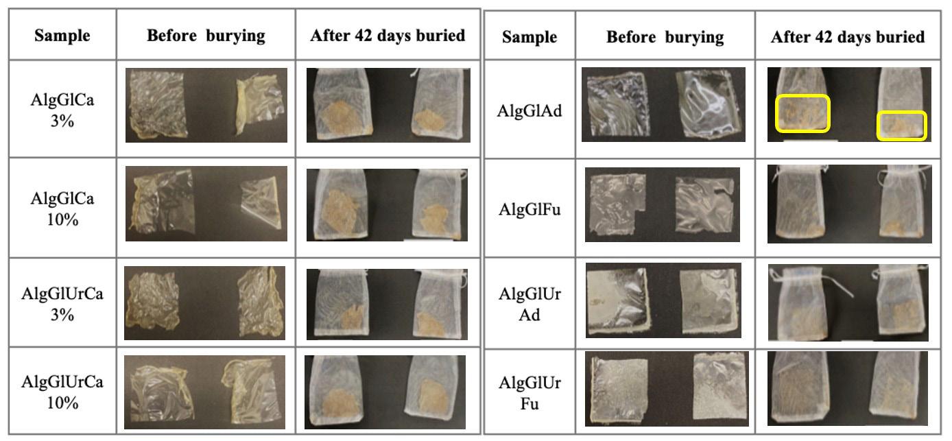
While a certain degree of biodegradability for films based on chitosan plasticized with glycerol was observed over 17 weeks[32]. Films made from Solanum lycocarpum St. Hill starch plasticized with glycerol (5-20%) were completely degraded over 180 days[39]. This preliminary assessment of the behavior of alginate films modified with urea and cross-linked with different acids and Ca2+ ions demonstrated a degradation profile between that of other biodegradable films used for packaging.
TGA and DSC analyses revealed that the modified and cross-linked films exhibited an excellent resistance to thermal degradation, indicating superior stability under high-temperature conditions. In addition, FTIR analyses provided information on the molecular interactions in the films, indicating the formation of cross-links between the functional groups of sodium alginate, glycerol, and cross-linking agents. The results indicated that the modification of alginate films with glycerol and cross-linking with adipic acid or fumaric acid significantly affected their mechanical and viscoelastic properties.
The following conclusions were drawn regarding the biodegradation of alginate and modified alginate films in soil using different cross-linkers. Visual analyses were essential for assessing the morphology of the films, highlighting changes in their appearance and structural integrity over time. Variations in the concentrations of additives led to different biodegradation rates, which suggests the feasibility of tailoring the biodegradation of the films to meet specific application requirements, thus enhancing their potential use in structures that are intended for burial in soil.
5. Author’s Contribution
• Conceptualization – Nivaldo Ramos Júnior; Ana Paula Testa Pezzin; Denise Abatti Kasper Silva
• Data curation – Nivaldo Ramos Júnior; Denise Abatti Kasper Silva
• Formal analysis – Nivaldo Ramos Júnior; Ana Paula Testa Pezzin; Denise Abatti Kasper Silva
• Funding acquisition - Ana Paula Testa Pezzin; Denise Abatti Kasper Silva
• Investigation – Nivaldo Ramos Júnior; Denise Abatti Kasper Silva
• Methodology – Nivaldo Ramos Júnior; Ana Paula Testa Pezzin; Denise Abatti Kasper Silva
• Project administration – Ana Paula Testa Pezzin; Denise Abatti Kasper Silva
• Resources – Nivaldo Ramos Júnior; Denise Abatti Kasper Silva
• Software – NA.
• Supervision – Nivaldo Ramos Júnior; Ana Paula Testa Pezzin; Denise Abatti Kasper Silva
• Validation – Nivaldo Ramos Júnior; Ana Paula Testa Pezzin; Denise Abatti Kasper Silva
• Visualization – Nivaldo Ramos Júnior; Ana Paula Testa Pezzin; Denise Abatti Kasper Silva
• Writing – original draft – Nivaldo Ramos Júnior; Ana Paula Testa Pezzin; Denise Abatti Kasper Silva
• Writing – review & editing – Ana Paula Testa Pezzin; Denise Abatti Kasper Silva
6. Acknowledgments
This research work was funded by the Brazilian Coordination for the Improvement of Higher Education Personnel (CAPES).
7. References
1 Food and Agriculture Organization of the United Nations – FAO (2021). Assessment of agricultural plastics and their sustainability: a call for action. Rome: FAO https://doi.org/10.4060/cb7856en
Júnior, N., Pezzin A. P. T., & Silva, D. A. K.
2 Wawszczak, A., Kocki, J., & Kołodyńska, D. (2024). Alginate as a sustainable and biodegradable material for medical and environmental applications: the case studies. Journal of Biomedical Materials Research. Part B, Applied Biomaterials, 112(9), e35475 https://doi.org/10.1002/jbm.b.35475 PMid:39269132.
3. Rahman, M. M., Shahid, M. A., Hossain, M. T., Sheikh, M. S., Rahman, M. S., Uddin, N., Rahim, A., Khan, R. A., & Hossain, I. (2024). Sources, extractions, and applications of alginate: a review. Discover Applied Sciences, 6(8), 443 https://doi. org/10.1007/s42452-024-06151-2
4 Qamar, S. A., Qamar, M., Basharat, A., Bilal, M., Cheng, H., & Iqbal, H. M. N. (2022). Alginate-based nano-adsorbent materials: bioinspired solution to mitigate hazardous environmental pollutants. Chemosphere, 288(Pt 3), 132618 https://doi. org/10.1016/j.chemosphere.2021.132618 PMid:34678347.
5 Benettayeb, A., Guibal, E., Morsli, A., & Kessas, R. (2017). Chemical modification of alginate for enhanced sorption of Cd(II), Cu(II) and Pb(II). Chemical Engineering Journal, 316, 704-714 https://doi.org/10.1016/j.cej.2017.01.131
6. Llive, L. M., Perullini, M., Santagapita, P. R., SchneiderTeixeira, A., & Deladino, L. (2020). Controlled release of fertilizers from Ca(II)-alginate matrix modified by yerba mate (Ilex paraguariensis) waste. European Polymer Journal, 138, 109955 https://doi.org/10.1016/j.eurpolymj.2020.109955
7 Lüdke, J. V. (1993). Efeito da inclusão de ácido fumárico em rações com dois níveis de derivados lácteos sobre o desempenho de leitões desmamados aos 23 dias de idade (Master’s dissertation). Universidade Federal do Rio Grande do Sul, Porto Alegre
8 Fujimoto, M. C. M. (2018). Modelagem e simulação de biorreator para produção de ácido fumárico (Undergraduate thesis). Universidade Federal de São Carlos, São Carlos. Retrieved in 2025, August 30, from https://repositorio.ufscar. br/handle/20.500.14289/15023
9 Ilica, R.-A., Kloetzer, L., Galaction, A.-I., & Caşcaval, D. (2019). Fumaric acid: production and separation. Biotechnology Letters, 41(1), 47-57 https://doi.org/10.1007/s10529-0182628-y PMid:30506453.
10 Sivashankari, P. R., & Prabaharan, M. (2017) Deacetylation modification techniques of chitin and chitosan. In J. A. Jennings, & J. D. Bumgardner (Eds.), Chitosan based biomaterials (pp. 117-133). Amsterdam: Woodhead Publishing https:// doi.org/10.1016/B978-0-08-100230-8.00005-4
11. van der Merwe, R. T., Goosen, N. J., & Pott, R. W. M. (2022). Macroalgal-derived alginate soil amendments for water retention, nutrient release rate reduction, and soil pH control. Gels, 8(9), 548 https://doi.org/10.3390/gels8090548 PMid:36135260.
12 Tan, J., Luo, Y., Guo, Y., Zhou, Y., Liao, X., Li, D., Lai, X., & Liu, Y. (2023). Development of alginate-based hydrogels: crosslinking strategies and biomedical applications. International Journal of Biological Macromolecules, 239, 124275 https:// doi.org/10.1016/j.ijbiomac.2023.124275 PMid:37011751.
13 Maity, C., & Das, N. (2021). Alginate-based smart materials and their application: recent advances and perspectives. Topics in Current Chemistry (Cham), 380(1), 3 https://doi.org/10.1007/ s41061-021-00360-8 PMid:34812965.
14. Gebresas, G. A., Szabó, T., & Kálmán Marossy, K. (2023). A comparative study of carboxylic acids on the cross-linking potential of corn starch films. Journal of Molecular Structure, 1277, 134886 https://doi.org/10.1016/j.molstruc.2022.134886
15 Coma, V., Sebti, I., Pardon, P., Pichavant, F. H., & Deschamps, A. (2003). Film properties from crosslinking of cellulosic derivatives with a polyfunctional carboxylic acid. Carbohydrate Polymers, 51(3), 265-271 https://doi.org/10.1016/S01448617(02)00191-1
16 Brioude, M. M., Guimarães, D. H., Fiúza, R. P., Prado, L. A. S. A., Boaventura, J. S., & José, M. N. (2007). Synthesis and characterization of aliphatic polyesters from glycerol, by-product of biodiesel production, and adipic acid. Materials Research, 10(4), 335-339 https://doi.org/10.1590/S151614392007000400003
17. Sigma-Aldrich. (2023). Ficha de dados de segurança: ácido adípico. Retrieved in 2025, August 30, from https://www. sigmaaldrich.com/BR/pt/sds/sigma/a26357?userType=anonymous
18 Yang, S. T., Zhang, K., Zhang, B., & Huang, H. (2011). Fumaric acid. In: M. Moo-Young (Ed), Comprehensive biotechnology (pp. 163-177). Oxford: Pergamon https://doi.org/10.1016/ B978-0-08-088504-9.00456-6
19 Wodtke, M. E. F., Apati, G. P., & Silva, D. A. K. (2023). Produção e caracterização de filmes à base de alginato visando à aplicação na área ambiental. Caderno de Iniciação à Pesquisa, 25, 168-174. Retrieved in 2025, August 30, from https://www.univille.edu.br/account/pesquisa/VirtualDisk. html/downloadDirect/3539631/Caderno_de_Iniciacao_a_ Pesquisa_Cientifica_PIBIC_2023_-_Volume_25.pdf
20 Leal, D., Matsuhiro, B., Rossi, M., & Caruso, F. (2008). FTIR spectra of alginic acid block fractions in three species of brown seaweeds. Carbohydrate Research, 343(2), 308-316. https://doi.org/10.1016/j.carres.2007.10.016 PMid:18048014.
21 Custódio, A. C., Ribeiro, R. P. S., Lima, T. B. S. L., Araújo, E. S., & Araújo, P. L. B. (2022). Purificação simplificada do rejeito de glicerina bruta da produção de biodiesel da biorrefinaria Berso-UFPE: uma prática sustentável. Revista Brasileira de Geografia Física, 15(5), 2226-2237 https://doi.org/10.26848/ rbgf.v15.5.p2226-2237
22. Draget, K. I., Smidsrød, O., & Skjåk-Bræk, G. (2005). Alginates from algae. In A. Steinbüchel (Ed.), Biopolymers online. Weinheim: Wiley-VCH https://doi.org/10.1002/3527600035.bpol6008
23 Manivannan, M., & Rajendran, S. (2011). Investigation of inhibitive action of urea-Zn2+ system in the corrosion control of carbon steel in sea water. International Journal of Engineering Science and Technology, 3(11), 8048-8060 Retrieved in 2025, August 30, from https://www.researchgate. net/publication/267782937_Investigation_of_inhibitive_ action_of_urea-Zn2_system_in_the_corrosion_control_of_ carbon_steel_in_sea_water
24 Piasek, Z., & Urbanski, T. (1962). The infrared absorption spectrum and the structure of urea. Bulletin de l’Académie Polonaise des Sciences. Série des Sciences Chimiques, 10, 113-120
25 Fransiska, D., Abdullah, A. H. D., Nurhayati, Irianto, H. E., Nissa, R. C., Sedayu, B. B., Syamani, F. A., Raharjo, S., Suwarti, & Agusman, (2024). Impact of agar–glycerol ratios on the physicochemical properties of biodegradable seaweed films: A compositional study. International Journal of Biological Macromolecules, 280(Pt 3), 135855 https://doi.org/10.1016/j. ijbiomac.2024.135855 PMid:39317277.
26 Fan, Y., Xu, J., Gao, X., Fu, X., & Yang, X. (2019). Effect of alginate on the release of amide nitrogen for soilless cultivation applications. Scientia Horticulturae, 256, 108545 https://doi. org/10.1016/j.scienta.2019.108545
27 Escobar-Avello, D., Ferrer, V., Bravo-Arrepol, G., ReyesContreras, P., Elissetche, J. P., Santos, J., Fuentealba, C., & Cabrera-Barjas, G. (2023). Pretreated Eucalyptus globulus and Pinus radiata barks: potential substrates to improve seed germination for a sustainable horticulture. Forests, 14(5), 991 https://doi.org/10.3390/f14050991
28 Marangoni, L., Jr., Rodrigues, P. R., Silva, R. G., Vieira, R. P., & Alves, R. M. V. (2021). Sustainable packaging films composed of sodium alginate and hydrolyzed collagen: preparation and characterization. Food and Bioprocess Technology, 14(12), 2336-2346 https://doi.org/10.1007/s11947-021-02727-7
Exploring urea and cross-linkers in alginate films for agricultural seedlings
29 Larosa, C., Salerno, M., Lima, J. S., Meri, R. M., Silva, M. F., Carvalho, L. B., & Converti, A. (2018). Characterisation of bare and tannase-loaded calcium alginate beads by microscopic, thermogravimetric, FTIR and XRD analyses. International Journal of Biological Macromolecules, 115, 900-906. https:// doi.org/10.1016/j.ijbiomac.2018.04.138 PMid:29704606.
30 Pratinthong, K., Punyodom, W., Jantrawut, P., Jantanasakulwong, K. , Tongdeesoontorn , W. , Sriyai , M. , Panyathip , R. , Thanakkasaranee, S., Worajittiphon, P., Tanadchangsaeng, N., & Rachtanapun, P. (2024). Modification of a carboxymethyl cellulose/poly(vinyl alcohol) hydrogel film with citric acid and glutaraldehyde crosslink agents to enhance the antiinflammatory effectiveness of triamcinolone acetonide in wound healing. Polymers, 16(13), 1798 https://doi.org/10.3390/ polym16131798 PMid:39000654.
31 . Hou, L., & Wu, P. (2019). Exploring the hydrogen-bond structures in sodium alginate through two-dimensional correlation infrared spectroscopy. Carbohydrate Polymers, 205, 420-426 https:// doi.org/10.1016/j.carbpol.2018.10.091 PMid:30446124.
32 Santana, M. C. C. B. (2012). Formulação, caracterização e eficácia antioxidante de filmes biodegradáveis ativos a base de quitosana, glicerol e aditivos naturais (Master’s dissertation). Universidade Federal da Bahia, Salvador
33 Wang, B., Wan, Y., Zheng, Y., Lee, X., Liu, T., Yu, Z., Huang, J., Ok, Y. S., Chen, J., & Gao, B. (2018). Alginate-based composites for environmental applications: a critical review. Critical Reviews in Environmental Science and Technology, 49(4), 318-356 https:// doi.org/10.1080/10643389.2018.1547621 PMid:34121831.
34. Turbiani, F. R. B., Kieckbusch, T. G., & Gimenes, M. L. (2011). Release of calcium benzoate from films of sodium alginate cross-linked with calcium ions. Polímeros Ciência e
Tecnologia, 21(3), 175-181 https://doi.org/10.1590/S010414282011005000034
35. Cacuro, T. A. (2019). Compósitos de alginato como material inteligente, modulação de solubilidade e objeto de ensino (Doctoral thesis). Universidade Federal de São Carlos, São Carlos. Retrieved in 2025, August 30, from https://repositorio. ufscar.br/handle/20.500.14289/12093
36 Lorandi, N. P. A., Cioffi, M. O. H., & Ornaghi, H., Jr. (2016). Dynamic Mechanical Analysis (DMA) of polymeric composite materials. Scientia Cum Industria, 4(1), 48-60 https://doi. org/10.18226/23185279.v4iss1p48
37 Moura, M. F. S., Morais, A. B., & Magalhães, A. G. (2005). Materiais compósitos: materiais, fabrico e comportamento mecânico Porto: Publindústria
38 Lucena, C. A. A., Costa, S. C., Eleamen, G. R. A., Mendonça, E. A. M., & Oliveira, E. E. (2017). Desenvolvimento de biofilmes à base de xilana e xilana/gelatina para produção de embalagens biodegradáveis. Polímeros, 27(spe), 35-41 https://doi.org/10.1590/0104-1428.2223
39. Fernandes, A. S., Cardoso, J. C. O., Gomes, J. N., & Ascheri, D. P. R. (2019). Elaboração e caracterização de filmes biodegradáveis de amido de Solanum lycocarpum St. Hill e glicerol. Fronteira: Journal of Social, Technological and Environmental Science, 8(1), 362-378 https://doi.org/10.21664/2238-8869.2019v8i1.p362-378
Received: Aug. 30, 2025
Revised: Nov. 26, 2025
Accepted: Dec. 03, 2025
Editor-in-Chief: Sebastião V. Canevarolo
Jair Francisco Souza Magalhães1* , Larissa dos Santos Borges1 , Roberto Yuri Costa Dias2 , Jerson Rogério Pinheiro Vaz1 and Roberto Tetsuo Fujiyama1
1Laboratório de Materiais Compósitos, Programa de Pós-graduação em Engenharia Mecânica, Universidade Federal do Pará – UFPA, Belém, PA, Brasil
2Laboratório de Materiais Compósitos, Faculdade de Engenharia Mecânica, Universidade Federal do Pará –UFPA, Belém, PA, Brasil
*jairfranciscomag@gmail.com
Obstract
Hybrid laminates are formed by layers of different reinforcements in a matrix to combine distinct properties. Hybridization aims to leverage the advantages of materials, creating a composite with greater mechanical performance and sustainability. This study investigates the replacement of synthetic reinforcements by natural ones. Six composite configurations are analyzed, using glass (G) and jute (J) fabrics with 145 GSM and 245 GSM, respectively, two pure (GGG and JJJ) and four hybrids (GJG, GVG, GGJ and JJG), produced by manual lamination followed by compression. The tensile strength tests (σ), according to ASTM D3039, revealed that the GJG (σ = 87.37 MPa) presented performance closer to the GGG (σ = 89.60 MPa), followed by the GGJ, JJJG, JGJ and JJJ. The resistance is mainly influenced by the sequence of layers, method of manufacture and volumetric fraction of reinforcements. Despite the manufacturing limitations, composites have demonstrated viability for applications with lower structural requirements.
Keywords: fractography, hybrid polymer composites, mechanical properties, sustainability.
Data Ovailability: All data supporting the findings of this study are available from the corresponding author upon request.
How to cite: Magalhães, J. F. S., Borges, L. S., Dias, R. Y. C., Vaz, J. R. P., & Fujiyama, R. T. (2026). Mechanical performance of laminated boards using polyester with jute and glass fabrics. Polímeros: Ciência e Tecnologia, 36(1), e20260012. https://doi.org/10.1590/0104-1428.20250083
Synthetic materials, especially those derived from oil, are increasingly being replaced by natural and renewable options, driven by market trends that emphasize environmental protection across several industrial sectors. This transition has motivated research on composites materials, defined as mixtures of different elements combined to achieve specific properties[1 2]
Widely used in automotive and aeronautical industries for weight reduction and mechanical efficiency, composites have gained renewed attention with the sustainable appeal of plant-based natural fibers. This practice aims to produce alternatives to synthetic fibers, such as glass, which are widely used[3-11]. Therefore, plant fibers are evaluated as promising due to factors such as availability, biodegradability, low cost and interesting physicalmechanical properties[12-18] .
Research with this bias has already been carried out globally. The use of additives such as nanoclay in synthetic and natural fiber hybrid polymer composites has already been investigated[19], resulting in improvements in mechanical and wear resistance. The authors proposed hybrid composites obtained from E-glass fiber mat,
with a thickness of 1 mm and a density of 2.6 g/cm3. In addition to the variation in the type of reinforcement, the influence of the addition of nanoclay was also considered, allowing discussion of how glass morphology, processing conditions, and the presence of additives can affect mechanical behavior.
It is known that in the case of hybrid laminates, the sequence of layer positioning can significantly alter stress transfer, stress distribution, and, consequently, the overall performance of the material. In this context, it is essential to assess how different structural configurations can contribute to mitigating losses in mechanical properties, while expanding the potential for partial replacement of synthetic reinforcements with natural fibers, aligning technical performance and sustainability.
In addition to the choice of constituent materials, the arrangement of layers in laminates is a determining factor for final performance. It has been shown that different stacking sequences between natural and synthetic fibers can significantly alter properties such as tensile and flexural strength, with alternating arrangements providing superior results[20]
Magalhães, J. F. S., Borges, L. S., Dias, R. Y. C., Vaz, J. R. P., & Fujiyama, R. T.
Furthermore, the mechanical performance of polymer composites is strongly associated with three main factors: type of matrix, volume fraction of reinforcements and manufacturing method. The choice of matrix directly influences interfacial adhesion and tensile strength. Studies show that resins such as epoxy generally provide better mechanical results when compared to other matrices, such as polyester or polyethylene[21,22] although polyester is still widely used due to its cost-effectiveness[23] .
The manufacturing process has a direct impact on the mechanical properties of composite materials[24]. Research shows that methods such as infusion and vacuum lamination provide better impregnation, less porosity and greater mechanical resistance than the hand lay-up method[25-27] Despite this, the hand lay-up method has advantages due to its low cost and simplicity, still viable for mediumperformance composite materials[28]
The volume fraction of the reinforcements is also decisive, as it has a direct impact on the stiffness, strength and energy absorption of the final material. Hybrid composites that properly integrate natural and synthetic fibers can optimize structural performance while reducing environmental
impact compared to conventional materials of exclusively synthetic origin[29-32] Table 1 shows the characteristics of hybrid composites with different glass (G) and jute (J) fiber stacking configurations found in academic literature.
Previous studies have described different failure modes depending on the stacking configuration. Figure 1 compiles the main highlights observed in the fracture regions in different types of hybrid composites with polymeric matrices reinforced by glass (G) and jute (J) fibers, according to various authors.
The present study aimed to contribute to the development of sustainable composites by investigating the feasibility of replacing synthetic reinforcements with natural fibers, prioritizing the analysis of the influence of layer arrangement in hybrid laminates. Six composite configurations laminated with polyester matrix reinforced with jute (J) and glass (V) fabrics in different positions are evaluated: two pure GGG and JJJ and four hybrid arrangements - GVG, GJG, GGJ and JJG. Combinations are identified that minimizes losses in mechanical performance compared to pure synthetic composite, while incorporating materials with a lower environmental impact.
Author σ (MPa)
Souza et al.[33] 73.49 (± 6.20) GGJ
73.03 (± 3.58) GJG
48.46 (± 4.16) GJJ
67.13 (± 4.86) JGJ
Almeida et al.[34] 86.35 (± 2.25) JGJ Polyester Hand lay-up 12.48 (m/m) 6.00 (m/m)
Varela[35] 40.88 (± 1.74) GJGJGJGJ Polyester Compression molding
Hasan et al.[36] 121.134 JGGJ Epoxy Vacuum infusion
(m/m)
(m/m) 115.284 GJJG - (400)
Queiroz et al.[37] 20.26 (± 1.44) JJGJJ Polyester Hand lay-up -(200) -(306)
Mahmud et al.[38] ~50 JGGJ Polyester Hand lay-up
(360) 50.00~100.00 GJJG
Gujjala et al.[39] 116.00 GGGG Epoxy Hand
52.00 JJJJ
GJGJ
JGGJ
84.00~88.00 GJJG
Costa et al.[40] 18.53 (±3.49) JJGJJ Polyester Hand lay-upFontes[41] 40.10 (±2.70) JJGJJ Polyester Hand
Alves[42] 199.70 (± 11.4) GJJG Epoxy Vacuum
Sezgin & Berkalp[43] 37.84 JJJJ Polyester Vacuum
GGGG
JGJG
JGGJ
GJJG
Mahmud et al.[44] 140.86 GGJJJJGG Polyester Compression molding
JJGGGGJJ
Mechanical performance of laminated boards using polyester with jute and glass fabrics
A polymer matrix unsaturated terephthalic polyester resin was used, supplied by Ara Química, under the trade name Arazan AZ 1.0 #34. The resin was cured by adding methyl ethyl ketone peroxide (MEKP), commercially identified as Permec D-45, in a proportion of 0.7% by volume, according to the manufacturer’s recommendations. Table 2 shows the properties of the resin, which is widely used in industry due to its good mechanical performance, ease of processing and low cost.
Bi-directional glass fiber and jute fabrics were used as reinforcement materials, with weights of 145 GSM and 245 GSM, respectively. The fabrics were purchased from a local business and manually cut, 0.28 m x 0.32 m, to enable the reinforcement layers to be assembled in the configurations defined for lamination. Figure 2 shows how the fabric arrangements with laminated composites are arranged.
The experimental procedures used to produce the composites, from the preparation of laminated plates to the removal of specimens for tensile strength tests and fractographic analysis, are illustrated in Figure 3.
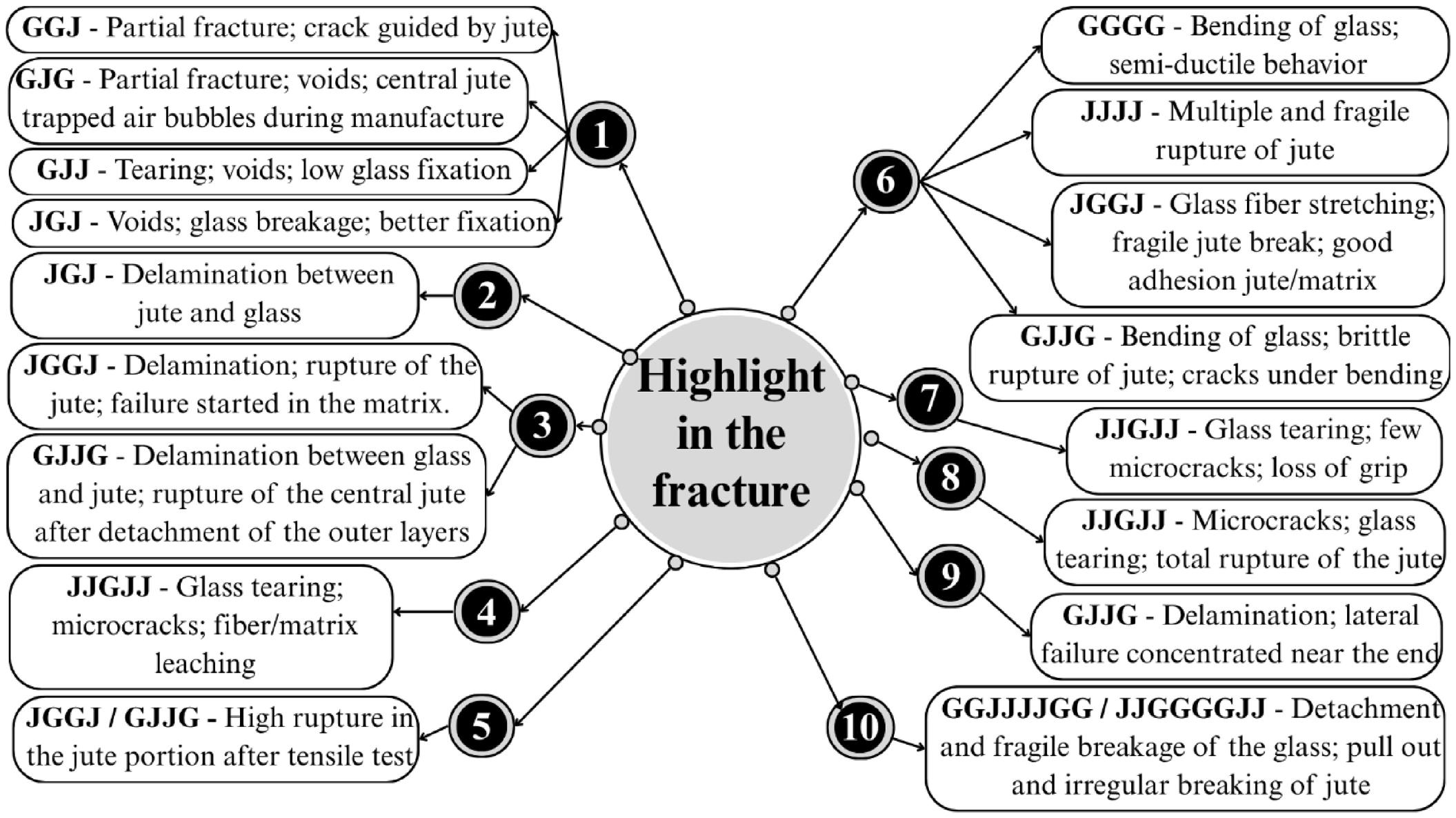
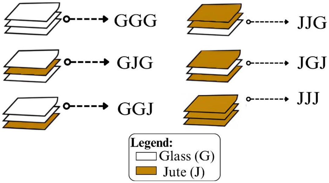
Source: Hul and Clyne[45]
Magalhães, J. F. S., Borges, L. S., Dias, R. Y. C., Vaz, J. R. P., & Fujiyama, R. T.
The jute and fiberglass fabrics were cut into 0.28 m × 0.32 m sections. A total of 24 fabrics, 9 of which are fiberglass (145 GSM) and 15 jute (245 GSM). After cutting, the process of manufacturing the laminated boards began to produce the six composites.
Four boards were made with hybrid reinforcement configurations and two with non-hybrid reinforcements. Before the lamination stage, the fabrics are weighed on a precision scale, and the jute fabrics were evaluated at two points: before and after drying in an oven for five minutes, to eliminate the moisture. The average loss of mass due to drying the jute is 10.24%.
Each laminated composite was molded using two plywood boards with dimensions of 0.36 m × 0.40 m × 0.013 m, previously coated with transparent polyester film (transparency for back projection) and adhesive tape, as shown in Figure 4a. The reinforcing fabrics (glass and jute) are positioned between the plywood sheets, according to the apparatus shown in Figure 4b
Once the lamination process is complete, the assemblies are placed in a hydraulic press, where a load of 0.5 tons is applied for a period of two hours, allowing the materials to cure properly. At the end of the process, the final laminated plates are obtained.
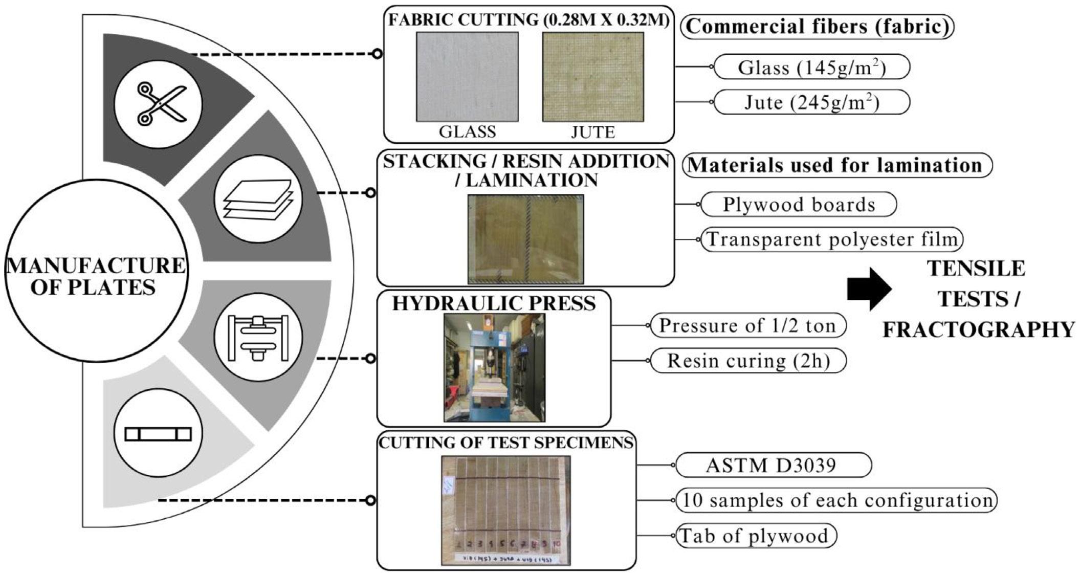
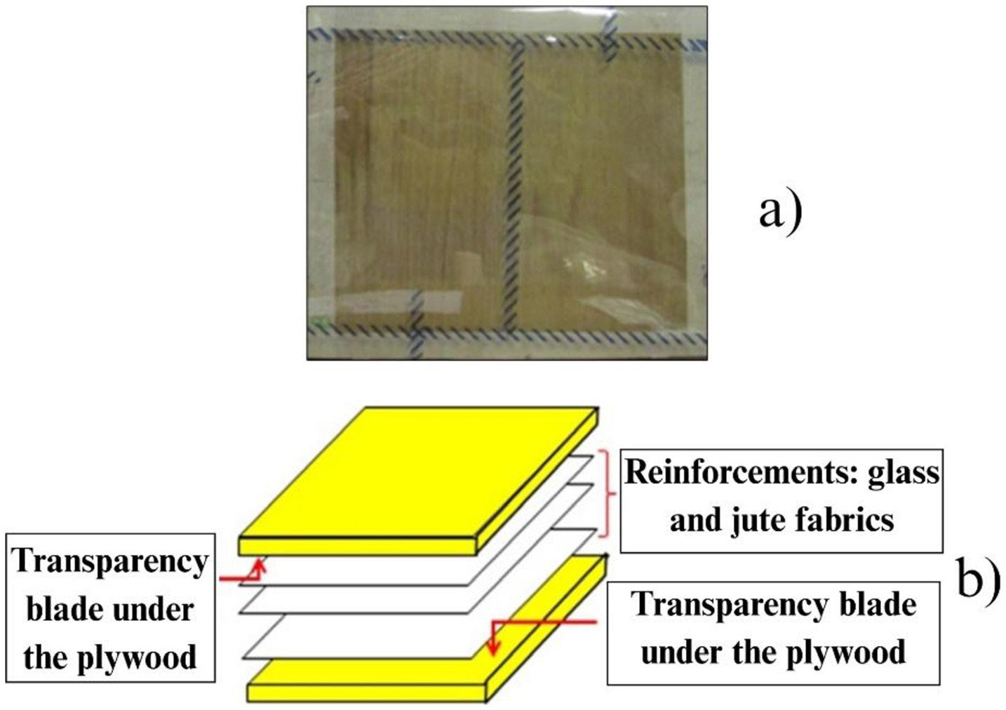
Mechanical performance of laminated boards using polyester with jute and glass fabrics
After the manufacturing stage of the plates, they were subsequently sectioned to obtain the test specimens, according to the dimensions standardized by ASTM D3039. Each plate allowed an average of 10 specimens to be made. Figure 5a shows an example of a plate after making the necessary cuts to extract the specimens. To prepare these samples, reinforcement tabs (Tabs) are glued at the ends using Tek Bond structural adhesive no. 725, as shown in Figure 5b
Three types of materials are evaluated for making the Tabs: plywood, glass and 180 granulation sandpaper, with plywood being the preferred material adopted in most samples tested. The tensile tests were carried out in accordance with the procedures established in the ASTM D3039 standard, at the Materials Engineering Laboratory of the Federal Institute of Pará (IFPA), located in Belém-PA.
The tests were performed on an Arotec universal testing machine, model WDW-100E, operating at a load application speed of 2 mm/min and a load cell with a capacity of 5 kN, under room temperature conditions. Once the tensile strength tests had been completed, the fracture surfaces of the specimens were analyzed to identify the main failure mechanisms involved. A visual analysis was carried out using a stethoscope.
The manufacturing process produced boards with uniform geometry and good surface finish, ensuring consistent tensile behavior. Polyester sheets during pressing improved surface leveling, resin impregnation, and handling, while the pressure applied during the first 24 h of curing was crucial for the final composite quality.
The tensile tests were satisfactory, as the specimens failed in the region of the useful length. The use of tabs to protect the ends of the specimens was efficient, as no crushing or slipping occurred during the tests. Table 3 shows the properties stress at maximum load (σ [MPa]) and modulus of elasticity (E [GPa]).
It is found that from the increase in the volumetric fraction of jute, there are losses of stiffness and mechanical strength. Figure 6 shows the characteristic Stress x Strain curves of the composites reinforced by the combination of jute and glass to evaluate the mechanical behavior of the materials produced.
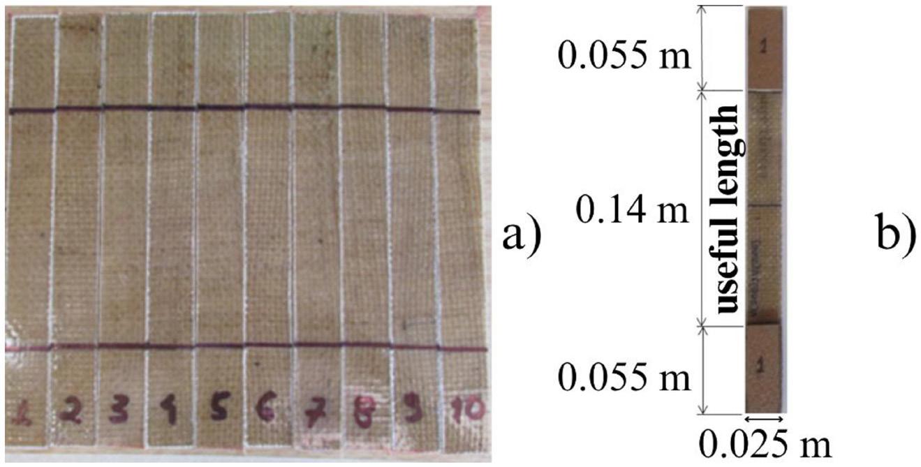
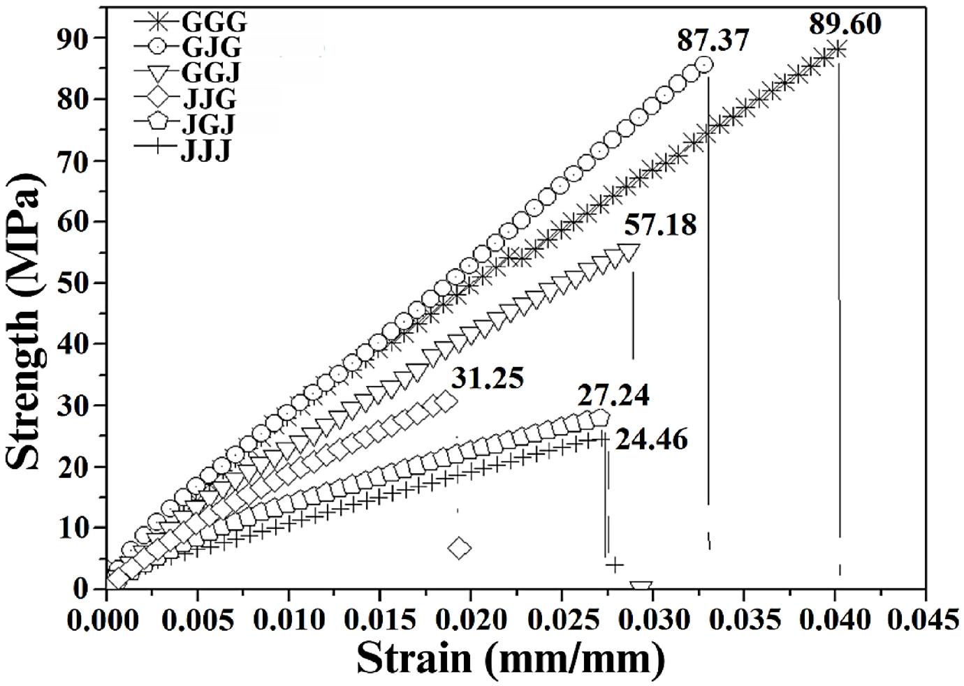
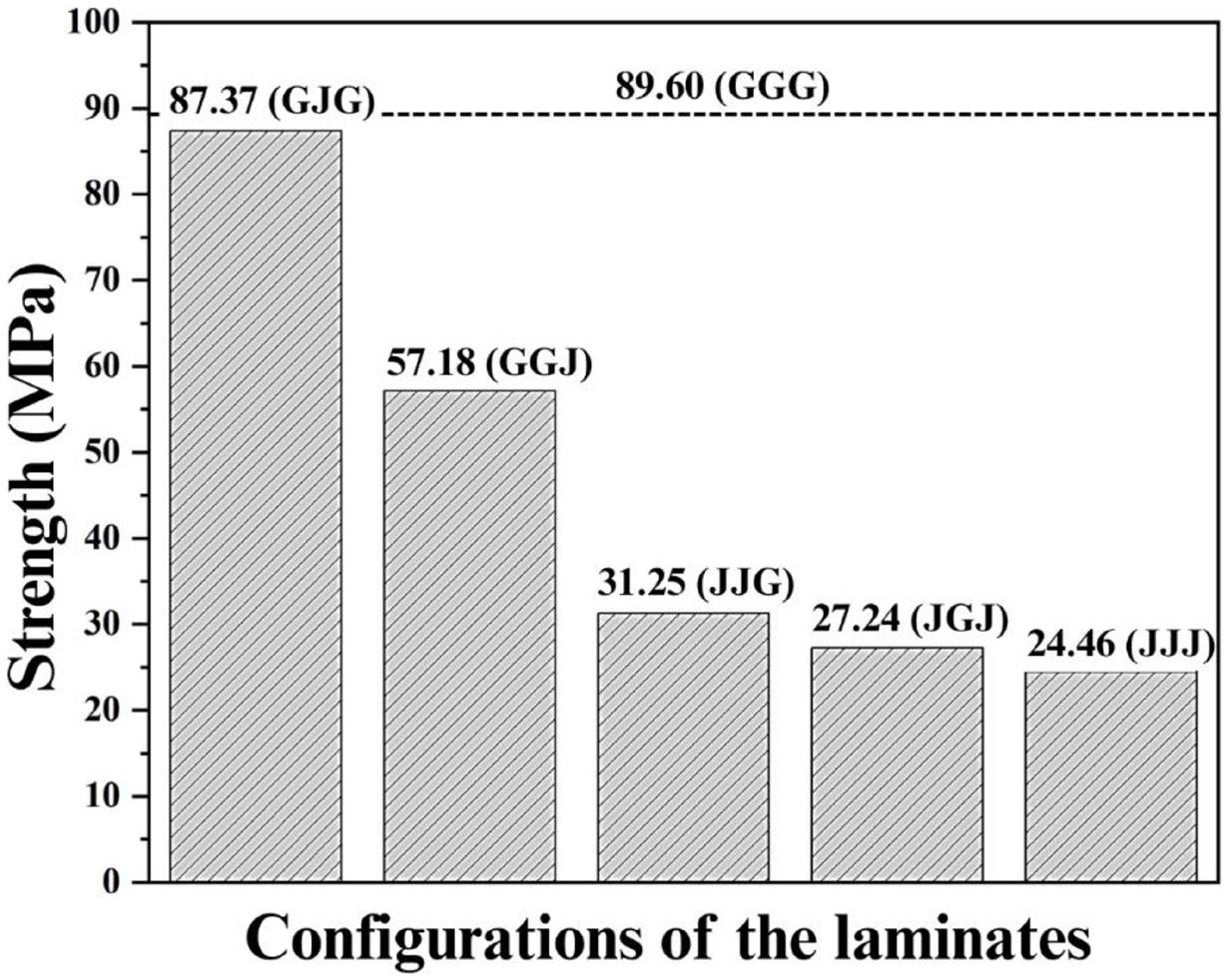
The graph, based on the mean curves of each stacking configuration, shows that laminates with more fiberglass layers (GGG, GJG, GGJ) present greater deformations. Replacing one glass layer with jute in the GJG configuration slightly reduces tensile strength (≈2.5%) but increases stiffness (≈3.4%). However, positioning jute at the laminate end (GGJ) causes larger losses (≈36.2% in strength and 19.6% in stiffness). The JJG hybrid, with two jute layers, reduces strength and modulus by 65.12% and 38.72%, respectively, while the JGJ configuration shows even greater losses (≈69.6% and 54.9%). Full replacement with jute (JJJ) leads to the most significant reduction, with strength and stiffness 72.70% and 57.02% lower than GGG. Figure 7 compares these results with the purely synthetic laminate.
Relating the results presented to values obtained in the literature, it can be seen that although polyester resin has inferior mechanical properties compared to epoxy[21 23] , the efficiency of stacking and the synergy between the reinforcements, especially in the GJG configuration, compensate for its limitations, as reinforced by Jiang et al.[22] , who highlighted the importance of the matrix-reinforcement interface in load transfer and mechanical performance.
The limitations of manual lamination, such as greater porosity and lower impregnation quality[25,26], justify the lower resistance compared to vacuum infusion[27,28] Even so, pressure applied with a hydraulic press reduced
defects, improving performance and showing that layer arrangement optimization can offset process limitations, as in GJG. Although GGG had the highest strength, hybrids with less glass fiber (GJG and JJG) also performed well, confirming that combining natural and synthetic fibers allows good mechanical properties with lower cost and environmental impact[29-31]
Almeida et al.[34] that explored the configuration JGJ in polyester matrix through the technique of manual lamination obtained a superior tensile strength, even using less efficient manufacturing method with regard to obtaining better mechanical properties of the composites produced, as the authors used continuous and longitudinally aligned fibers in relation to the application of the tractive load, sense that gives the material greater mechanical strength. However, in the present study, bidirectional woven fabrics were employed, whose discontinuous yarn structure and higher heterogeneity reduce the efficiency of stress transfer, which may justify the lower tensile strength observed in comparison.
Higher jute fabric contents, as reported by Queiroz Jr.[37] and da Costa et al.[40], led to lower tensile strength across all configurations analyzed. Fontes[41] also obtained lower resistance than the present GJG and GGJ hybrids, while Mahmud et al.[44] reported superior results, associated with a higher number of glass fiber layers. The asymmetrical stacking sequence also influences mechanical behavior.
Mechanical performance of laminated boards using polyester with jute and glass fabrics
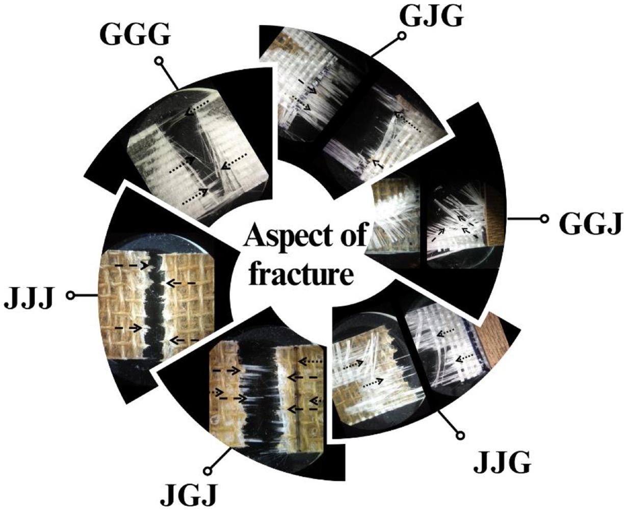
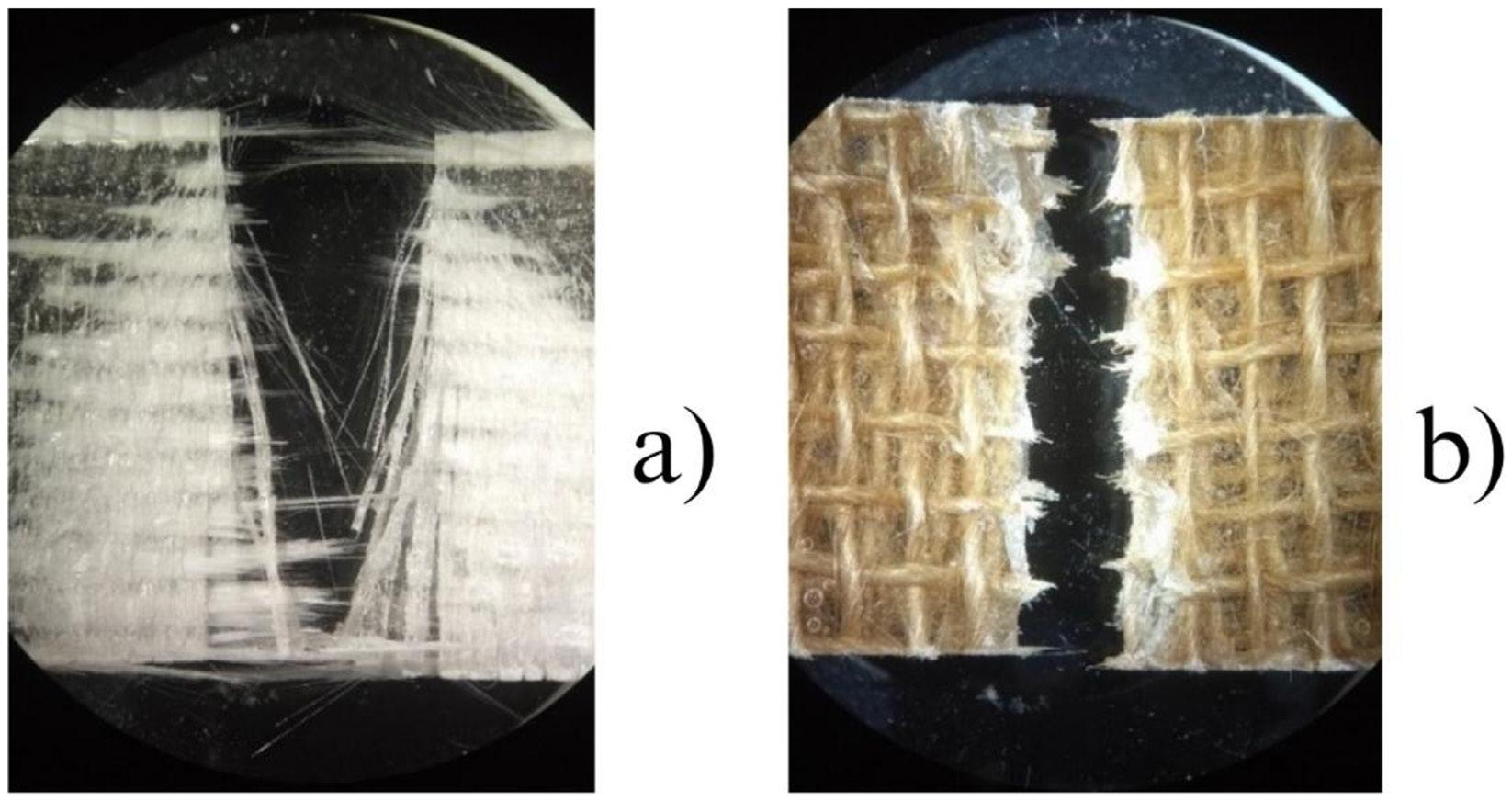
Varela[35] proposed the GJGJGJGJJ laminate, which showed inferior performance compared to GJG and GGJ of this study, indicating that alternating natural and synthetic layers does not benefit composite strength.
For the understanding of the variation of the composite’s properties, the fractographic analysis of the region, where the failures occurred is fundamental. Figure 8 shows the failure surface of the test samples with all stacking configurations to be assessed.
After testing, the total fracture samples is observed for all stacking configurations, without partial ruptures. Figure 9 exposes the fracture surface of the purely synthetic (a) (GGG) and natural (b) (JJJ) composites.
A linear fracture is verified for the configurations (GGG) and natural (JJJ) with rupture of the warp wires,
in the direction of longitudinal alignment, in relation to the applied loading. The JJJ break can be described as fragile and multiple, consistent with the pattern described above for pure jute laminates, Gujjala et al.[39] Such failure modes are attributed to the discontinuous structure of jute yarns, which results in lower energy absorption capacity before rupture. Figure 10 shows the fracture aspect of the samples manufactured with stacking (a) GJG and (b) GGJ.
In GJG (Figure 10a), both jute layers fractured in the weft and warp regions (dotted arrows), along with glass fibers (pointed arrows), which broke in the longitudinal loading direction, resulting in symmetric fracture without fiber orientation variation, consistent with reports of central jute rupture in intermediate laminates[36,38,44]. In GGJ (Figure 10b), the jute fabric detached earlier than the glass reinforcement, and only the glass fibers fractured (dashed arrows), showing post-failure orientation variation, a mechanism also previously observed[33]
J. F. S., Borges, L. S., Dias, R. Y. C., Vaz, J. R. P., & Fujiyama, R. T.
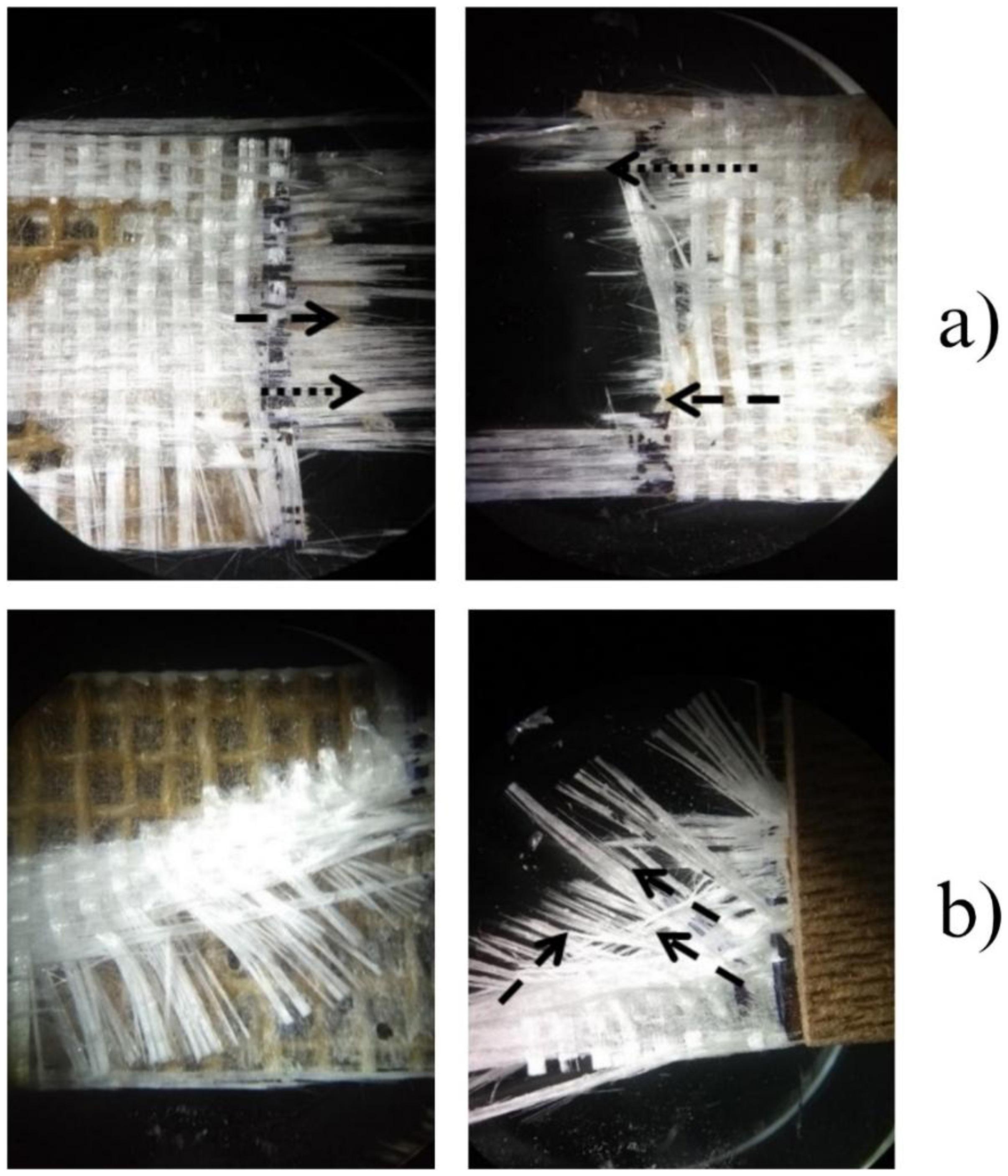
Therefore, if one layer of the synthetic reinforcement GGG composite is replaced by natural reinforcement, GJG and GGJ configurations, different property values are found due to the influence of the material layer. The symmetrical aspect of GJG configuration provided greater mechanical strength due to greater effectiveness of the synthetic reinforcement in resisting the longitudinal load without change in orientation of the warp wires. Figure 11 shows the fracture aspect of test samples (a) JJG and (b) JGJ.
For the hybrid laminates JJG and JGJ, fracture mainly affected the glass fibers due to their higher resistance, with rupture aligned to the fabric warp. In JJG (Figure 11a), the glass layer detached (dashed arrows), explained by material heterogeneity and the two consecutive jute layers, which increased the natural fraction’s response under tensile loading, ensuring good resistance. In JGJ (Figure 11b),
jute and glass fibers fractured similarly, indicating balanced stress distribution. This effect results from placing the glass layer at the core, improving its fixation[33] .
Thus, replacing two glass fabric layers with two jute layers causes greater mechanical performance loss than replacing only one. This occurs due to the fabric constitution: jute yarns are formed from short, randomly sized macerated fibers, while glass yarns consist of aligned continuous fibers, which better resist tensile load along the warp direction. It should be noted that, while most of the studies available in the literature present representative images or point micrographs with generic descriptions of fracture aspects, even of different hybrid configurations, this study opted for a more targeted approach, focusing individually on the failure modes observed in each of the six laminate configurations.
Mechanical performance of laminated boards using polyester with jute and glass fabrics
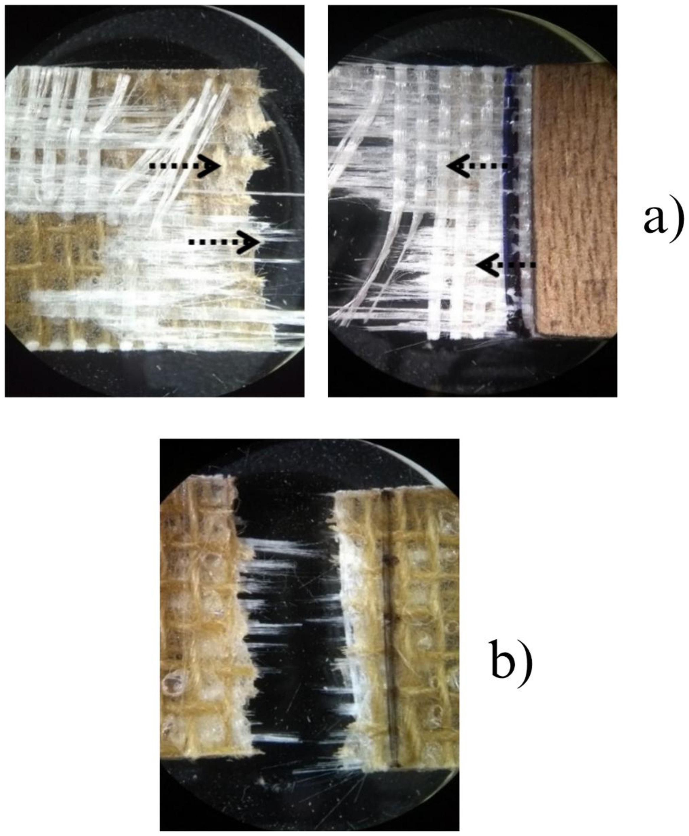
Based on the adopted procedures and results, replacing synthetic reinforcements with natural fibers, combined with suitable stacking, can yield hybrid composites with satisfactory performance. The GJG configuration showed tensile behavior similar to the purely synthetic laminate (GGG), indicating that jute as an intermediate layer does not significantly reduce strength. Layer sequence, volumetric fraction, and manufacturing process directly affect behavior, and although manual lamination limits uniformity, the hybrids proved viable for low to medium structural applications. Thus, jute incorporation appears as a sustainable alternative, reducing environmental impact and enabling use in less critical sectors. Additionally, the detailed fractographic analysis of the six laminate configurations, uncommon in
the literature, revealed specific failure mechanisms related to stacking, providing technical insights for future optimization of hybrid composites.
5. Author’s Contribution:
• Conceptualization – Jair Francisco Souza Magalhães; Larissa dos Santos Borges; Roberto Yuri Costa Dias; Roberto Tetsuo Fujiyama.
• Data curation – NA.
• Formal analysis – Jair Francisco Souza Magalhães.
• Funding acquisition – Jerson Rogério Pinheiro Vaz; Roberto Tetsuo Fujiyama.
• Investigation – Jair Francisco Souza Magalhães; Larissa dos Santos Borges; Roberto Yuri Costa Dias.
Magalhães, J. F. S., Borges, L. S., Dias, R. Y. C., Vaz, J. R. P., & Fujiyama, R. T.
• Methodology – Larissa dos Santos Borges.
• Project administration – Roberto Tetsuo Fujiyama.
• Resources – Jerson Rogério Pinheiro Vaz; Roberto Tetsuo Fujiyama.
• Software – NA.
• Supervision – Roberto Tetsuo Fujiyama.
• Validation – Roberto Yuri Costa Dias.
• Visualization – Larissa dos Santos Borges; Roberto Yuri Costa Dias.
• Writing – original draft – Jair Francisco Souza Magalhães; Larissa dos Santos Borges; Roberto Yuri Costa Dias; Jerson Rogério Pinheiro Vaz.
• Writing – review and editing – Jerson Rogério Pinheiro Vaz; Jair Francisco Souza Magalhães; Roberto Tetsuo Fujiyama.
The authors would like to thank PROPESP/UFPA for the Institutional Scientific Initiation Scholarship Program (PIBIC) and the scholarships awarded to undergraduate students. They would also like to thank CAPES, CNPq and the Composite Materials Laboratory at the Federal University of Pará for the experiments carried out in this work. The authors gratefully acknowledge the support of FEM/ITEC/UFPA, PPGEM/ITEC/UFPA and financial support from the Human Resources Program of the National Agency of Petroleum, Natural Gas and Biofuels – PRH-ANP.
7. References
1. Levy, F., No., & Pardini, L. C. (2006). Compósitos estruturais: ciência e tecnologia São Paulo: Edgar Blucher
2 Hsissou, R., Seghiri, R., Benzekri, Z., Hilali, M., Rafik, M., & Elharfi, A. (2021). Polymer composite materials: a comprehensive review. Composite Structures, 262, 113640 https://doi.org/10.1016/j.compstruct.2021.113640
3. Rodrigues, J., & Fujiyama, R. (2010). Mechanical behavior of polyester and sisal fibers (SAE Technical Paper; 2010–36–0409). In SAE Brasil 2010 Congress and Exhibit Warrendale: SAE International. https://doi.org/10.4271/2010-36-0409.
4 Zerin, N., Quinlan, P., & Simon, L. (2022). Optimum formulation design of natural fiber-reinforced composites (NFRC) for automotive applications. Journal of Composite Materials, 56(9), 1407-1415 https://doi.org/10.1177/00219983221076205
5 Dias, R. Y. C., Soares, R. V., Maia, P. V. M., Santos, J. E. M., Miranda, I. R. S., Paschoal, W. G., Jr., & Fujiyama, R. T. (2024). Preliminary indication approach of jute fiber fabric with polyester for bumpers of passenger cars (SAE Technical Paper; 2024–36–0149). In SAE Brasil 2024 Congress. Warrendale: SAE International https://doi.org/10.4271/2024-36-0149
6 Soares, R. V., Dias, R. Y. C., Maia, P. V. M., Paschoal, W. G., Jr., & Fujiyama, R. T. (2024). Presentation of biocomposites for proposal for use in car bumpers (SAE Technical Paper; 2024–36–0148). In SAE Brasil 2024 Congress Warrendale: SAE International https://doi.org/10.4271/2024-36-0148
7 Mendonça, A. G. S., Dias, R. Y. C., Soares, R. V., Borges, L. S., Maia, P. V. M., & Fujiyama, R. T. (2024). Polyester composite and waste of natural materials recyclable fracture aspect after tensile test. Revista De Gestão Social E Ambiental - RGSA, 18(5), e08181 https://doi.org/10.24857/rgsa.v18n5-180
8 Lima, L. S., Branco, C. T. N. M., Santos, R. M. C., Lima, F. V. M., Costa, D. S., El Banna, W. R., & Fujiyama, R. T. (2013). Laminated composite of sisal and curaua fibers to different settings for use in bumper cars (SAE Technical Paper; 2013–36–0603). In 22nd SAE Brasil International Congress and Display Warrendale: SAE International https://doi. org/10.4271/2013-36-0603
9. Branco, C. T. N. M., Figueiredo, J. M. S., Veloso, M. J. G., & Fujiyama, R. T. (2017). Modelling a rear bumper of goods transport vehicle made of glass fiber reinforced polymer (SAE Technical Paper; 2017–36–0413). In 26th SAE Brasil International Congress and Display Warrendale: SAE International https:// doi.org/10.4271/2017-36-0413.
10 Maciel, L. P., Leão, P. S., Jr., Pereira, M. J., Fo., El Banna, W. R., Fujiyama, R. T., Ferreira, M. P., & Lima, A. F., No. (2024). Experimental analysis of shear-strengthened RC beams with jute and jute–glass hybrid FRPs using the EBR technique. Buildings, 14(9), 2893 https://doi.org/10.3390/ buildings14092893
11 Borges, L. S., Santos, J. E. M., Dias, R. Y. C., Vilhena, E. S., Vilhena, E. S., Brandao, L. W. M., & Fujiyama, R. T. (2025). Influência das configurações de empilhamento na caracterização mecânica de compósitos de poliéster reforçados com fibras de juta. Matéria, 30, e20250385 https://doi.org/10.1590/15177076-rmat-2025-0385
12 Dias, R. Y. C., Simões, M. A. C., Jr., Maia, P. V. M., Veloso, M. J. G., & Fujiyama, R. T. (2023). Comparison of theoretical and experimental maximum stress of polyester composite and aligned sisal fibers (SAE Technical Paper; 2023–36–0104). In SAE Brasil 2023 Congress Warrendale: SAE International https://doi.org/10.4271/2023-36-0104
13 Sanjay, M. R., Arpitha, G. R., Naik, L. L., Gopalakrishna, K., & Yogesha, B. (2016). Applications of natural fibers and its composites: an overview. Natural Resources, 7(3), 108-114 https://doi.org/10.4236/nr.2016.73011
14 Karimah, A., Ridho, M. R., Munawar, S. S., Ismadi, Amin, Y., Damayanti, R., Lubis, M. A. R., Wulandari, A. P., Nurindah, Iswanto, A. H., Fudholi, A., Asrofi, M., Saedah, E., Sari, N. H., Pratama, B. R., Fatriasari, W., Nawawi, D. S., Rangappa, S. M., & Siengchin, S. (2021). A comprehensive review on natural fibers: technological and socio-economical aspects. Polymers, 13(24), 4280 https://doi.org/10.3390/polym13244280 PMid:34960839.
15 Ghalme, S., Hayat, M., & Harne, M. (2025). Comprehensive review of natural fibers: bio-based constituents for advancing sustainable materials technology. Journal of Renewable Materials, 13(2), 273-295 https://doi.org/10.32604/jrm.2024.056275
16 Ajayi, N. E., Rusnakova, S., Ajayi, A. E., Ogunleye, R. O., Agu, S. O., & Amenaghawon, N. A. (2025). A comprehensive review of natural fiber reinforced polymer composites as emerging materials for sustainable applications. Applied Materials Today, 43, 102666 https://doi.org/10.1016/j.apmt.2025.102666
17 Carvalho, M., Valente, J. C., Xavier, M., Silva, F., Raiol, J. A., Rodrigues, L. D., & Fujiyama, R. (2017). Use of green composites for manufacturing small boats in the Amazon: numerical and experimental evaluations. Matéria (Rio de Janeiro), 22(2), e11828 https://doi.org/10.1590/s1517-707620170002.0160
18 Batista, M. S., Teixeira, L. A., Louly, A. S., Silva, S. O., & Luz, S. M. (2022). Fatigue damage propagation and creep behavior on sisal/epoxy composites. Polímeros: Ciência e Tecnologia, 32(1), e2022008 https://doi.org/10.1590/0104-1428.20210093
19 Manickam, S., Kannan, T. K., Simon, B. L., Rathanasamy, R., & Raj, S. S. (2020). Influence of nanoclay on the technical properties of glass-abaca hybrid epoxy composite. Polímeros: Ciência e Tecnologia, 30(4), e2020038 https://doi.org/10.1590/01041428.08520
Polímeros, 36(1), e20260012,
Mechanical performance of laminated boards using polyester with jute and glass fabrics
20 Banu, M., Madhavan, V. R. B., Manickam, D., & Devarajan, C. (2021). Experimental investigation on stacking sequence of Kevlar and natural fibres/epoxy polymer composites. Polímeros: Ciência e Tecnologia, 31(1), e2021004 https://doi.org/10.1590/01041428.04320
21. Pereira, W. A., Ceron, I., Silva, M. S., Freitas, M. P. C., Silva, E. R., & Costa, F. M. (2021). Desenvolvimento de compósitos poliméricos reforçados com fibra da folha do buriti. Matéria, 26(1), e12932 https://doi.org/10.1590/s1517-707620210001.1232
22. Jiang, L., Zhou, Y., Jin, F., & Hou, Z. (2023). Influence of polymer matrices on the tensile and impact properties of long fiber-reinforced thermoplastic composites. Polymers, 15(2), 408 https://doi.org/10.3390/polym15020408 PMid:36679287.
23 Karaçor, B., & Özcanlı, M. (2021). Effect of various matrix materials on mechanical properties of basalt/jute/glass fiber reinforced hybrid composites. Çukurova Üniversitesi Mühendislik Fakültesi Dergisi, 36(4), 941-954. https://doi. org/10.21605/cukurovaumfd.1040514
24 Wu, C., Xu, F., Wang, H., Liu, H., Yan, F., & Ma, C. (2023). Manufacturing technologies of polymer composites - a review. Polymers, 15(3), 712 https://doi.org/10.3390/polym15030712 PMid:36772013.
25 Najafi, M., Eslami, F. R., & Khalili, S. M. R. (2012). Comparison of compressive properties between vacuum infusion and hand lay-up method toward balsa core sandwich composites. Journal of Mechanical Research and Application, 4(2), 33-40 Retrieved in 2025, September 9, from https://www.sid.ir/EN/ VEWSSID/J_pdf/1000620120205.pdf
26 Bittencourt, A. P. P., Dutra, G. B., & Tancredi, T. P. (2016). Efeito dos processos de laminação sobre as propriedades físicas e mecânicas de compósitos de resina de poliéster com fibras de vidro. Matéria (Rio de Janeiro), 21(4), 11763 https://doi. org/10.1590/s1517-707620160004.0094
27 Abdurohman, K., Satrio, T., Muzayadah, N. L., & Teten, (2018). A comparison process between hand lay-up, vacuum infusion and vacuum bagging method toward e-glass EW 185/ lycal composites. Journal of Physics: Conference Series, 1130, 012018 https://doi.org/10.1088/1742-6596/1130/1/012018
28 Ashrith, H. S., Jeevan, T. P., & Xu, J. (2023). A review on the fabrication and mechanical characterization of fibrous composites for engineering applications. Journal of Composites Science, 7(6), 252 https://doi.org/10.3390/jcs7060252
29. Angrizani, C. C., Amico, S. C., Cioffi, M. O. H., & Zattera, A. J. (2014). Influência da espessura nas propriedades mecânicas de compósitos híbridos interlaminares de curauá/vidro/poliéster. Polímeros: Ciência e Tecnologia, 24(2), 184-189 https://doi. org/10.4322/polimeros.2014.063.
30 Saleem, A., Medina, L., Skrifvars, M., & Berglin, L. (2020). Hybrid polymer composites of bio-based bast fibers with glass, carbon and basalt fibers for automotive applications - a review. Molecules (Basel, Switzerland), 25(21), 4933 https:// doi.org/10.3390/molecules25214933 PMid:33113848.
31 Nurazzi, N. M., Asyraf, M. R. M., Athiyah, S. F., Shazleen, S. S., Rafiqah, S. A., Harussani, M. M., Kamarudin, S. H., Razman, M. R., Rahmah, M., Zainudin, E. S., Ilyas, R. A., Aisyah, H. A., Norrrahim, M. N. F., Abdullah, N., Sapuan, S. M., & Khalina, A. (2021). A review on mechanical performance of hybrid natural fiber polymer composites for structural applications. Polymers, 13(13), 2170 https://doi.org/10.3390/polym13132170 PMid:34209030.
32 Sanjay, M. R., Arpitha, G. R., & Yogesha, B. (2015). Study on mechanical properties of natural-glass fibre reinforced polymer hybrid composites: A review. Materials Today: Proceedings, 2(4–5), 2959-2967 https://doi.org/10.1016/j.matpr.2015.07.264
33 Souza, J. H. S., Rocha, T. O. S., Gomes, I. S., Nascimento, A. S., Silva, D. S., Nascimento, E. S., & Fujiyama, R. T. (2019). Materiais compósitos de matriz poliéster com reforço híbrido de tecido de fibras de juta e mantas de fibra de vidro.
Brazilian Applied Science Review, 3(1), 777-790 https://doi. org/10.34115/basr.v3i1.881
34 Almeida, L. M., Branco, C. T. N. M., Silva, D. S., Oliveira, E. G., Fo., & Fujiyama, R. T. (2020). Compósitos poliméricos híbridos com fibras naturais e sintéticas contínuas e alinhadas. In H. A. Holzmann (Ed.), Evolução na ciência e engenharia de materiais (pp. 10–22). Ponta Grossa: Atena Editora https:// doi.org/10.22533/at.ed.2192016012.
35 Varela, P. H. A. (2017). Obtenção, caracterização e aplicabilidade de um compósito com matriz de resina ortoftálica e reforços de tecidos de juta (Corchorus capsularis) hibridizado com fibra de vidro (Doctoral Thesis). Universidade Federal do Rio Grande do Norte, Natal
36 Hasan, M. M., Islam, M. A., & Hassan, T. (2024). Analysis of jute-glass fiber reinforced epoxy hybrid composite. Heliyon, 10(24), e40924 https://doi.org/10.1016/j.heliyon.2024.e40924. PMid:39720052.
37 Queiroz, M. I., Jr., Carvalhaes, V., Vilela, T. S. V., Carvalho, A. C. J., Oliveira, L. T., Bueno, P. M. F., & Tinô, S. R. L. (2022). Compósito polimérico de fibras de juta e vidro-e como potencial uso em próteses/órteses: Propriedades mecânicas e configurações. In H. A. Holzmann (Ed.), Engenharia & ciência dos materiais (pp. 50–65). Ponta Grossa: Atena Editora https:// doi.org/10.22533/at.ed.0392209064
38 Mahmud, S. H., Akram, M. W., Ferdous, S. M. R., Islam, D., Fatema, K., Chowdhury, M. S. A., Das, A., & Ovi, S. M. (2024). Fabrication and mechanical performance investigation of jute/glass fiber hybridized polymer composites: effect of stacking sequences. Next Materials, 5, 100236 https://doi. org/10.1016/j.nxmate.2024.100236
39. Gujjala, R., Ojha, S., Acharya, S. K., & Pal, S. K. (2014). Mechanical properties of woven jute–glass hybrid-reinforced epoxy composite. Journal of Composite Materials, 48(28), 3445-3455. https://doi.org/10.1177/0021998313501924.
40 Costa, A. A., Santos, B. O., Oliveira, L. S., Tinô, S. R. L., Carvalhaes, V., Vilela, T. S. V., Queiroz, M. I., Jr., & Pimenta, P. H. N. (2024). Propriedades mecânicas em compósito polimérico híbrido de fibras de juta/vidro-E e potencial uso estrutural. In J. P. Ayoub, & M. R. N. Oliveira (Eds.), Materiais de engenharia: fundamentos e novas tendências (pp. 128–141). São Paulo: Editora Científica Digital https://doi.org/10.37885/231115009
41. Fontes, R. S. (2013). Compósito polimérico híbrido: comportamento mecânico, descontinuidade geométrica e resistência residual (Master’s dissertation). Universidade Federal do Rio Grande do Norte, Natal
42. Alves, J. L. C. (2017). Obtenção e caracterização de laminados de compósitos poliméricos híbridos de fibras de juta a partir de laminados de fibras de vidro utilizados na fabricação de pás eólicas (Master’s dissertation). Universidade Federal de São Carlos, São Carlos
43 Sezgin, H., & Berkalp, O. B. (2017). The effect of hybridization on significant characteristics of jute/glass and jute/carbonreinforced composites. Journal of Industrial Textiles, 47(3), 283-296 https://doi.org/10.1177/1528083716644290
44 Mahmud, S. H., Das, S. C., Saha, A., Islam, T., Paul, D., Akram, M. W., Jahan, M. S., Mollah, M. Z. I., Gafur, M. A., & Khan, R. A. (2025). Effect of glass fiber hybridization and radiation treatment to improve the performance of sustainable natural fiber-based hybrid (jute/glass) composites. Next Sustainability, 6, 100104. https://doi.org/10.1016/j.nxsust.2025.100104.
45 Hull, D., & Clyne, T. W. (1996). An introduction to composite materials (2nd ed.). Cambridge, UK: Cambridge University Press
Received: Sept. 09, 2025
Revised: Nov. 25, 2025
Accepted: Dec. 05, 2025
Associate Editor: Artur J. M. Valente

São Paulo 994 St. São Carlos, SP, Brazil, 13560-340
Phone: +55 16 3374-3949
Email: abpol@abpol.org.br 2021