KWB – lifting point ULD
Lifting Point ULD
1
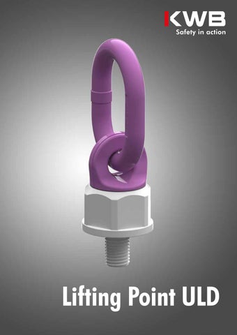
Lifting point ULD The lifting point ULD is equipped with a ball bearing and is rotatable 360° even under load. The high-strength lifting ring is movable by 180°. The screw is 100 % crack-tested and protected against corrosion. The safety factor is 4:1. • Made in Europe • Rotatable under load due to ball bearing • Rotatable 360 degrees • Crack-tested bolt • Ring is movable • Safety factor 4:1 • Metric • Color change depending on temperature • Corrosion protected (body powder-coated) • 3D drawings available • Stock item for fast delivery • Supplied with operating manual and thread protection
Code
ULD 0,75t ULD 1,5t ULD 2,5t ULD 4t ULD 6t
Thread
Working load limit
a
b
c
d
e
f
n
B
Weight
[mm]
[kg]
[mm]
[mm]
[mm]
[mm]
[mm]
[mm]
[mm]
[mm]
[kg/pc.]
M12 M16 M20 M24 M30
750 1.500 2.500 4.000 6.000
35 38 35 40 50
55 64 64 75 96
10 13 14 17 23
50 47 54 68 92
115 125 150 180 230
40 45 60 75 95
20 24 30 36 45
36 41 55 70 85
0,40 0,65 1,30 2,30 4,60
Ball-bearing mounted lifting point
2
Method of lifting Number of legs Angle of inclination
Code
Thread
1 0°
1 90°
2 0°
2 90°
2 0-45°
2 45°-60°
3+4 0°-45°
3+4 45°-60°
2 asymm.
3+4 asymm.
Working load limit (G)
[mm]
Fastening torque [Nm]
ULD 0,75 t
M12
15
1.200
750
2.400
1.500
1.060
750
1.590
1.120
750
750
ULD 1,5 t
M16
30
2.600
1.500
5.200
3.000
2.120
1.500
3.180
2.250
1.500
1.500
ULD 2,5 t
M20
70
4.000
2.500
8.000
5.000
3.500
2.500
5.300
3.750
2.500
2.500
ULD 4 t
M24
150
7.000
4.000
14.000
8.000
5.600
4.000
8.400
6.000
4.000
4.000
ULD 6 t
M30
230
10.000
6.000
20.000
12.000
8.480
6.000
12.720
9.000
6.000
6.000
[kg]
Safety factor 4:1
180°
Permitted usage For working load limits in the permitted directions of pull, please refer to the working load limit table.
Permissible load directions
Non-permitted usage During assembly, ensure that improper loading does not arise due to any of the following factors: • Direction of pull is obstructed • Direction of pull is not within the indicated area • Loading ring rests against edges or loads The lifting points are ball-bearing mounted. However, to prevent the ring from jamming, it is recommended to align it in the permitted and required direction of pull prior to loading (fig. Permissible load directions). This is particularly relevant when lifting loads with multi-leg chain slings. If the ring is not aligned (fig. Nonpermissible load directions), the ring holder could suddenly turn, causing a significant risk to loads and operators.
Non-permissible load directions
ULD - Operating Manual
KWB – lifting point ULD
The full operating manual contains further details and information on safe usage.
3
Subject to technical changes and printing errors.
KWB Ketten Austria GmbH A-9020 Klagenfurt, Schleppe-Platz 8 Phone: +43 463 48 80-355 Fax: +43 463 48 80-350 kwb@kwb-ketten.at, www.kwb-ketten.at
FO/25/00484