GEEG, startup di Sapienza, Università di Roma, affianca grandi società di Ingegneria, Imprese, fornitori di tecnologie e materiali nei processi di Ricerca e Sviluppo mediante procedure sperimentali e protocolli innovativi utili in ogni fase, dal progetto fino ai controlli in corso d’opera.
Cerchi uno spazio in cui informarti su cosa succede nel mondo del sotterraneo? Iscriviti alla newsletter
Terra Terra - Down to Earth Tutto l'underground in un unico posto
Gallerie e Grandi Opere Sotterranee
Anno XLVII - N. 156 - Dicembre 2025
Periodico trimestrale, riconosciuto dal C.N.R., della Società Italiana Gallerie – Italian Tunnelling Society – Member of ITA/AITES
ISSN: 0393-1641/S. Anagrafe Naz. delle Ricerche: cod. 318915PS
Direttore Responsable: Enrico Maria Pizzarotti
Direttrice Editoriale: Daniela Boldini
Caporedattore: Renzo Bindi
Comitato di Redazione: Lorenzo Batocchioni, Andrea Carigi, Remo Di Lorenzi, Chiara Spaggiari
Responsabile Gestione Editoriale: Diego Sebastiani Segretaria di Redazione: Ludovica Roda Hanno collaborato a questo numero: Rocco Amodeo, Cristina Baldini, Marianna Brichese, Mario Calicchio, Ignazio Carbone, Elena Consoli, Hannes Ertl, Giuliano Faini, Federico Foria, Francesco Gamba, Francesco Ippolito, Andrea Lattanzi, David Marini, Maurizio Martino, Valerio Mele, Alessandro Micheli, Mathias Neuenschwander, Francesco Panico, Sergio Pedemonte, Luca Puletti, Diego Sebastiani, Valentino Sevino, Agostino Viglione.
Editore:
S.I.G. Società di Servizi S.r.l. Via Giovanni da Procida, 7 – 20149 Milano, (MI) Tel.: +39 02 25715805; Tel./Fax: +39 02 25708152 www.societaitalianagallerie.com
e-mail: info@societaitalianagallerie.it
Gestione editoriale abbonamenti e pubblicità: Casa Editrice Prof. Riccardo Pàtron & C. S.r.l. Via Marsala, 31 – 40126 Bologna, (BO) Tel. 051 767003 www.patroneditore.com
e-mail: info@patroneditore.com
Grafica e Impaginazione: Exegi Snc - Bologna Stampa: Tipografia Negri, Bologna - Dicembre 2025
SommarioSommario Sommario Sommario
3 Editoriale E. Pizzarotti
Intervista a: Stefania Stefanizzi
Responsabile della Sede di Torino di ARX Group Consigliere SIG 8 L. Puletti
Verso una contrattualistica collaborativa per le grandi opere infrastrutturali: l’evoluzione tra rischio geotecnico, standard FIDIC e modelli innovativi di alleanza
9 M. Neuenschwander, H. Ertl
Risk management and contractual aspects in underground works: an introduction to the Emerald Book
C. Baldini, I. Carbone, E. Consoli, F. Gamba, Z. Lostia, D. Marini, A. Viglione
The time adjustment for long crossborder Italian tunnels
F. Foria, M. Brichese, M. Calicchio, F. Panico
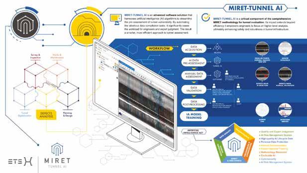
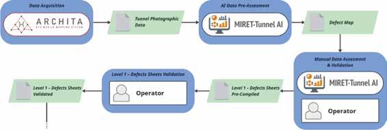
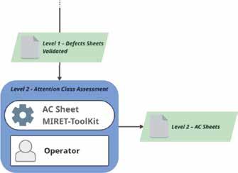
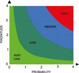
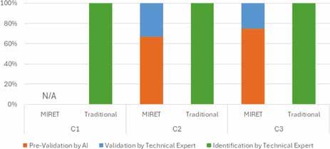
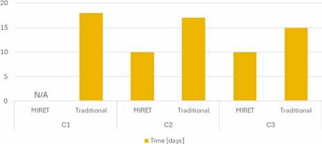
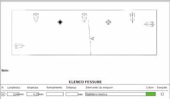
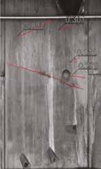
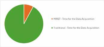
Exploitation of MIRET-Tunnel AI for the inspection of tunnels
V. Mele, A. Micheli, M. Martino, A. Lattanzi
Autorizzazione del Tribunale di Torino no 2638 del 25.11.76 Pubblicazione trimestrale ai soci della Società Italiana Gallerie
Le opinioni espresse dagli Autori non impegnano la Direzione. Tutti i diritti di riproduzione sono riservati. Abbonamenti 2025
Per abbonamenti e ordini di arretrati, rivolgersi all’Ufficio Abbonamenti: abbonamenti@patroneditore.com o collegarsi al sito www.patroneditore.com/riviste.html Per ricevere i pdf dell’intera Rivista può essere inoltrata richiesta alla Segreteria della Società Italiana Gallerie (segreteria@societaitalianagallerie.it)
I pdf dei singoli articoli e gli abbonamenti online possono essere richiesti solo collegandosi al sito www.patroneditore.com/riviste.html Gli abbonamenti hanno decorrenza gennaio-dicembre, con diritto di ricevimento dei fascicoli già pubblicati, se sottoscritti in corso d’anno. I fascicoli cartacei non pervenuti vengono reintegrati non oltre 30 giorni dopo la spedizione del numero successivo. Modalità di pagamento: Versamento anticipato adottando una delle seguenti soluzioni: – c.c.p. n. 000016141400 intestato a Casa Editrice Prof. Riccardo Pàtron & C. S.r.l. - via Badini 12 - Quarto Inferiore - 40057 Granarolo dell’Emilia - Bologna - Italia – bonifico bancario a INTESA SAN PAOLO SPA, Agenzia: Castenaso, Via XXV aprile 10-D, 40057 Granarolo dell’Emilia – Bologna – Italia
IBAN: IT98M0306936767100000008509
BIC: BCITITMM – carta di credito o carta prepagata a mezzo PAYPAL (www.paypal.it) specificando l’indirizzo e-mail amministrazione@patroneditore.com nel modulo di compilazione per l’invio della conferma di pagamento all’Editore.
Per pubblicare un articolo sulla Rivista Gallerie e Grandi Opere Sotterranee occorre inviare il manoscritto all’indirizzo redazione@societaitalianagallerie.it redatto secondo il format scaricabile dal sito www.societaitalianagallerie.it La revisione degli articoli è a cura del Comitato Editoriale della rivista, che si avvale di revisori anonimi. Le opinioni dell’Autore non impegnano l’Editorial Board, ma esclusivamente la responsabilità dell’Autore stesso che garantisce l’originalità del proprio manoscritto e l’assenza di vincoli e di licenze per la pubblicazione, lasciando indenne la rivista da qualsiasi onere presente e futuro.
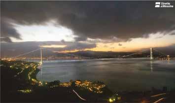
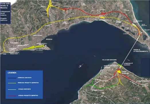
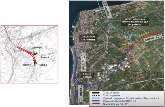
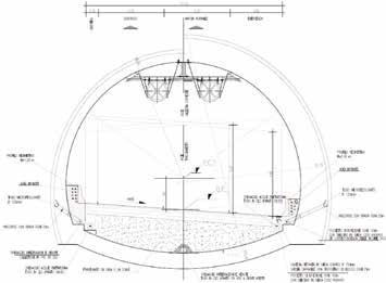
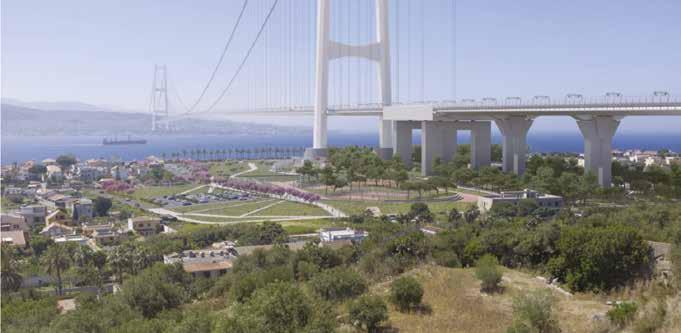
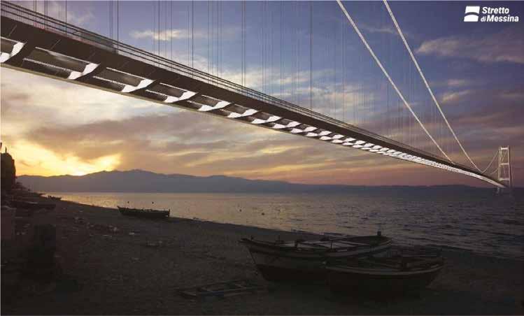
Not just a bridge for the Strait of Messina
Gallerie e Grandi Opere Sotterranee / Tunnels and Underground Works
Comitato Editoriale / Editorial Board
Direttore Responsabile / Editor-in-Chief Enrico Maria Pizzarotti, Pro Iter S.r.l.
Georgios Anagnostou ETH Zurich
Monica Barbero Politecnico di Torino
Marco Barla Politecnico di Torino
Marco Bettelini Amberg Engineering Ltd
Adam Bezuijen Ghent University
Direttrice Editoriale / Editorial Director Daniela Boldini, Sapienza University of Rome
Comitato Tecnico-Scientifico / Advisory Board
Daniela Boldini (Coordinatrice / Coordinator), Sapienza University of Rome
Lorenzo Brino, TELT S.a.s.
Salvatore Miliziano, Sapienza University of Rome
Daniele Peila, Politecnico di Torino
Alessandra Sciotti, Italferr S.p.A.
Antonio Voza, Proger S.p.A.
Membri del Comitato Editoriale / Editorial Board Members
Alessandro Damiani Lombardi Ingegneria S.r.l.
Tiziana De Angelis Anas S.p.A.
Nicola Della Valle TYLin
Claudio di Prisco Politecnico di Milano
Adriano R. Fava Alpina S.p.A.
Emilio Bilotta University of Naples “Federico II”
Roberto Bono WeBuild S.p.A.
Wout Broere Delft University of Technology
Carlos Carranza-Torres University of Minnesota
Marilena Cardu Politecnico di Torino
Giovanna Cassani Rocksoil S.p.A.
Elena Chiriotti INCAS partners
Massimo Concilia Autostrade per l’Italia S.p.A.
Stefano Fuoco Italferr S.p.A.
Robert Galler Montanuniversität Leoben
Anna Giacomini University of Newcastle
Giovanni Giacomin Ghella S.p.A.
Alessandro Graziani Roma Tre University
Georgios Kalamaras AK Ingegneria Geotecnica S.r.l.
Michael Kavvadas National Technical University of Athens
Zaira Lostia Impresa Pizzarotti & C. S.p.A.
Comitato di Redazione / Editorial Team
Renzo Bindi (Caporedattore / Head of the Editorial Team)
Chrysothemis Paraskevopoulou National Technical University of Athens
Giovanni Plizzari University of Brescia
Luca Soldo Pro Iter S.r.l.
Jie Zhang Tongji University
Luisella Vai SPERI S.p.A.
Diego Sebastiani (Responsabile Gestione Editoriale / Editorial Management Officer) Lorenzo Batocchioni, Andrea Carigi, Remo Di Lorenzi, Chiara Spaggiari (Redazione / Editorial Team)
Care Socie e cari Soci, scrivo queste righe la mattina del 4 dicembre, Santa Barbara, e mi è spontaneo esprimere a tutti voi gli auguri per la vostra attività legata alle opere sotterranee, che vorrei estendere idealmente a tutti gli operatori del settore.
Il 2 dicembre, SIG ha celebrato la Santa in anticipo, per consentire la presenza di chi può festeggiare anche oggi in una galleria, ricordando l’Ing. Adolfo Colombo, Presidente SIG negli anni 1991-1993 e 2001-2009, con la brillante Colombo Lecture del Prof. Kalman Kovari.
Posso affermare che quest’anno la nostra Santa Barbara ha riscosso un deciso successo, con il 30% in più delle presenze, dei patrocini e degli sponsor rispetto agli anni scorsi, anche grazie all’interesse delle relazioni sull’utilizzo delle gallerie per fini idraulici che si sono succedute prima della Lecture del Prof. Kovari da parte degli Ingg. Federica Mazzocchi e Fabio Marelli di Metropolitana Milanese e l’Ing. Matteo Botticelli di ACEA.
Non so se, come me, gli oltre 100 partecipanti alla celebrazione hanno respirato un’atmosfera particolarmente carica di emozione e amicizia: credo che la nostra protettrice “istituzionale” ci abbia aiutato a condividere il senso di partecipazione a tutto il mondo che si occupa di opere sotterranee e l’orgoglio di far parte di una comunità che merita di essere amata e protetta, per come svolge il proprio ruolo con passione, dedizione e competenza.
Queste occasioni di serenità e armonia, che fanno pensare a certi passi biblici in cui si profetizza che il “lupo dimorerà assieme all’agnello” (Isaia 11:6-9), non sono, purtroppo, così frequenti nella nostra consueta vita lavorativa. In particolare, e lascio a ognuno di voi stabilire da quale parte si trovino gli animali feroci e quelli indifesi, condizioni di tensione e di confronto più o meno aspro si manifestano quando tra le principali parti in causa, committenti e imprese costruttrici, nasce un contenzioso. Sappiamo che nel contesto delle opere sotterranee, data la loro peculiarità, le principali e più accese controversie nascono sull’interpretazione, sia tecnica che contrattuale, del cosiddetto “imprevisto geologico” (si vedano gli stimolanti esempi illustrati dal Prof. Kovari nella sua Lecture).
Le dispute di questo tipo, oltre a produrre effetti negativi e non prevedibili sulla gestione del contratto di appalto, prevalentemente in termini di tempi e costi, portano a una contrapposizione tra tutti gli attori del processo assolutamente non produttiva per instaurare un clima collaborativo per il raggiungimento del miglior risultato per tutti gli attori stessi
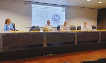
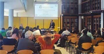
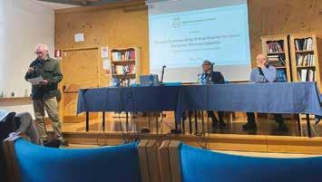
Proprio per indagare le possibilità di ridurre ai minimi termini queste vertenze, la SIG ha organizzato, nel contesto di ExpoFerroviaria, il 1° ottobre 2025, il seminario Gestione dei rischi e aspetti contrattuali nelle opere sotterranee, che ha previsto gli interventi di tre docenti esperti della materia (Avv. Luca Puletti, Ing. Matthias Neuenschwander e Ing. Hannes Hertl) e una stimolante tavola rotonda tra esperti rappresentanti dei committenti, degli appaltatori e dei progettisti consulenti, moderata dallo stesso Avv. Puletti e dall’Ing. Agostino Viglione, Animatore del Gruppo di Lavoro 3 della SIG, che ha recentemente prodotto il report “Il meccanismo del time adjustment per lunghe gallerie transfrontaliere italiane”. Ai docenti, che ringrazio ancora per la loro disponibilità e la qualità delle loro esposizioni - insieme agli altri partecipanti al successivo dibattito, è stato chiesto un contributo scritto, che i lettori di Gallerie e Grandi Opere Sotterranee troveranno proprio in questo numero.
Anche se non mi arrischio a profetizzare che grazie a questa iniziativa di SIG “il lupo e l’agnello pascoleranno assieme” (Isaia 65:25), posso affermare che il seminario ha riscosso un notevole interesse e alcuni temi trattati hanno evidenziato una favorevole convergenza di opinioni tra tutte le parti intervenute.
Ovviamente, contiamo sull’aiuto di Santa Barbara per compiere ulteriori passi avanti sia per questo che per altri aspetti riguardanti il nostro settore, ma posso promettervi che SIG non lo attenderà a braccia conserte.
Buona Santa Barbara, buon Natale e buon 2026
Enrico Maria Pizzarotti
Enrico Maria Pizzarotti.
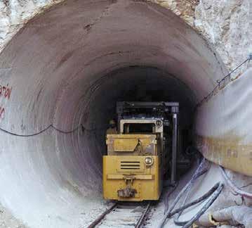
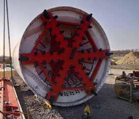
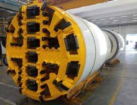
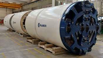
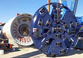
SOLUZIONI INNOVATIVE PER LO SCAVO DI OGNI GALLERIA
Depolveratori e ventilatori
Tappeti per nastri trasportatori
Controllo accessi in galleria
Veicoli speciali per gallerie
Casseri e impianti di produzione a carosello per conci
Impianti di separazione
Schiume e grassi
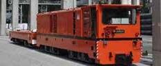
Locomotori e rolling stock
Passerelle pedonali per gallerie
Impianti bicomponente
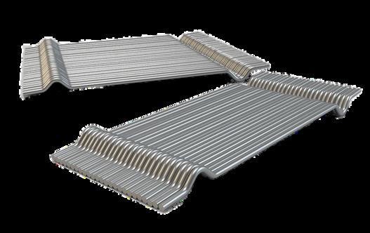
Ponti prefabbricati
Stefania Stefanizzi
Responsabile della Sede di Torino di ARX Group
Consigliere SIG
Siamo lieti di presentare l’ing. Stefania Stefanizzi, recentemente entrata nel Consiglio Direttivo SIG e rappresentante di spicco della nuova generazione di professionisti del tunnelling. Laureata e poi “dottorata” in Ingegneria Geotecnica presso il Politecnico di Torino, con un’esperienza di ricerca internazionale in Canada, Stefania ha maturato una solida carriera in Geodata S.p.A., specializzandosi nella progettazione di gallerie e lavorando su progetti infrastrutturali in diversi Paesi. Dal 2022 guida l’ufficio torinese di ARX Group, portando con sé competenza, equilibrio e una visione aperta e appassionata del nostro settore.
Grazie Stefania per essere qui con noi oggi. Puoi iniziare raccontandoci qualcosa di te e quando e come ti sei appassionata al mondo delle gallerie?
Quando mi iscrissi alla Facoltà di Ingegneria Civile non avevo la “vocazione” per la materia e nei primi anni dell’Università mi sono chiesta spesso se avessi fatto la scelta giusta. Lungo il mio percorso formativo e professionale ho avuto la fortuna e l’onore di incontrare persone di eccezionale caratura sia tecnica sia umana che mi hanno trasmesso la passione per questa professione e hanno segnato il mio percorso: Giovanni Barla, professore di Meccanica delle Rocce al Politecnico di Torino che, durante gli anni dell’Università prima e durante il percorso di Dottorato poi, mi ha fatto scoprire che l’interazione terreno struttura poteva avere un certo fascino e Piergiorgio Grasso che ha contribuito enormemente alla mia formazione lavorativa, insegnandomi che non esistono limiti geografici nel nostro mestiere, ma solo competenza, voglia di affrontare le sfide e un po’ di incoscienza e che l’entusiasmo e la positività non devono mai mancare anche nei momenti di difficoltà. È grazie a mentori come loro che mi sono appassionata al mondo delle gallerie e ho costruito il mio percorso fino ad arrivare a essere scelta come responsabile della sede di Torino di ARX, un grande gruppo internazionale di ingegneria, il cui Headquarter è in Svizzera, specializzato nel fornire soluzioni all’avanguardia in progetti complessi. Ed è per questo
che riconosco fortemente l’importanza dell’attività divulgativa e formativa che svolge la SIG, perché solo rappresentando la bellezza del nostro lavoro possiamo attrarre talenti e appassionare anche chi è un po’ scettico, come lo ero io all’inizio.
Ci racconti un progetto di cui sei particolarmente orgogliosa o a cui sei particolarmente legata?
Un solo progetto è un po’ limitativo! Lasciami almeno raccontare quelli che per me sono i miei 3 progetti iconici, quelli che hanno segnato la mia vita e rappresentato dei momenti chiave di crescita.
Il primo è sicuramente il progetto del corridoio stradale e ferroviario tra Adler e Kasnaya Poliana per le Olimpiadi Invernali di Sochi del 2014 in Russia, dove ho seguito la progettazione e la supervisione delle gallerie (un totale di circa 27 km di tunnels, divisi in 12 gallerie di cui 3 stradali, 6 ferroviarie, 3 cunicoli di emergenza, realizzati parte in tradizionale e parte in meccanizzato). Questa è stata un’occasione unica di crescita per me, non è stato facile guadagnare credibilità agli occhi del cliente e delle imprese
Stefania Stefanizzi.
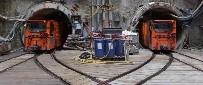
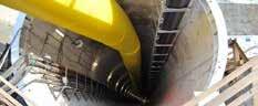
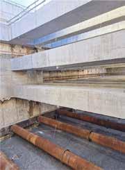
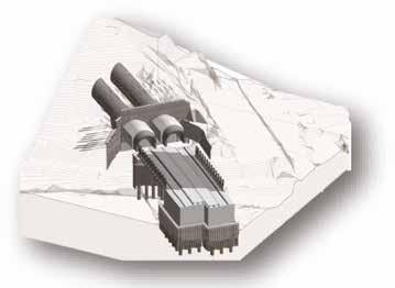
Galleria Stradale T3 del corridoio Adler – Krasnaya Poliana Sochi – scavo con TBM del solo ribasso. Complesso di tunnels T3 del corridoio Adler – Krasnaya Poliana Sochi.
russe, sia per la giovane età sia per il contesto tipicamente maschile, ma i ringraziamenti del capo cantiere a fine lavori li ricorderò per sempre con una punta di vero orgoglio. Tra l’altro in questo progetto abbiamo adottato una soluzione tecnica estremamente interessante, con la TBM che in alcune zone, come all’imbocco o per l’attraversamento di alcune zone di faglia, ha scavato il solo ribasso, dopo che la parte di calotta era già stata realizzata in tradizionale.
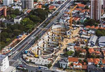
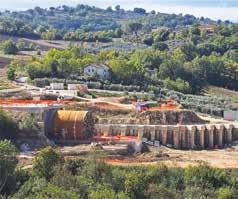
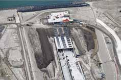
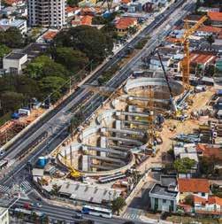
Poi mi piace ricordare il progetto dell’estensione della Linea 5 della Metropolitana di San Paolo, dove ho coordinato lo sviluppo della progettazione di 11 km di linea, parte a doppia canna con 2TBMs di diametro 6,9 m e parte a singola canna con una TBM da 10,58 m, di 10 stazioni, 10 pozzi di ventilazione e 3 manufatti speciali. Uno sforzo considerevole in termini di coordinamento e gestione delle interfacce, dove ho supervisionato la produzione di oltre 15.000 elaborati, con i centri di produzione sparsi in vari uffici distribuiti in Italia e in Brasile. Il progetto della stazione Brooklin, realizzata con cinque pozzi secanti di diametro 36 m per una lunghezza totale di 140 m e una profondità di 27 m, presenta molteplici elementi tecnici innovativi, che sono stati oggetto anche di riconoscimenti e di premi: i 5
pozzi sono stati scavati simultaneamente prevedendo l’utilizzo di diaframmi strutturali realizzati con idrofresa, utilizzando come puntoni provvisori le travi dell’opera definitiva e realizzando dei diaframmi speciali a forma di freccia nei punti di intersezione tra i pozzi.
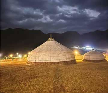
Infine, sono particolarmente legata al primo progetto sviluppato al mio ingresso in ARX nel 2022, un progetto ferroviario in Mongolia, sviluppato a livello di fattibilità, che prevede la realizzazione di due gallerie, da 8,6 km e 12,5 km rispettivamente, per bypassare la città di Ulaanbaatar. In questo progetto ho avuto la fortuna di affrontare un contesto lavorativo totalmente nuovo, con nuove sfide tecniche come l’analisi dell’interazione terreno-struttura in presenza di permafrost e, soprattutto, posso dire che, come ARX, abbiamo contribuito al primo progetto di tunnel mai sviluppato in Mongolia. E poi c’è un aspetto personale da non trascurare, ho avuto la possibilità di visitare il deserto del Gobi, vivendo l’esperienza in modo davvero autentico, accompagnata dal cliente locale.
Ovviamente, il successo in questi progetti non sarebbe stato possibile senza il contributo di tutto il gruppo di lavoro e di tutte quelle che in ARX ci piace chiamare ‘smart minds ’, che lavorano ogni giorno affianco a me e che non smetterò mai di ringraziare.
Ci hai parlato molto di progetti internazionali, e l’Italia?
Si, è vero ho parlato molto di progetti all’estero, ma sono convinta che nel nostro lavoro i confini siano relativi e che quello che conta sia solo la buona ingegneria, che siamo da sempre abituati ad esportare. Basti pensare ai tanti case history presentati nel Handbook on Tunnels ans Underground Works della SIG! Adesso comunque sto lavorando tanto anche per l’Italia e le sfide non sono affatto meno impegnative, anzi!
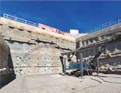
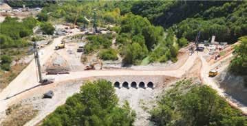
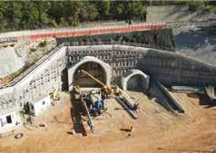
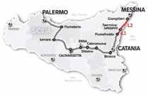
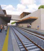
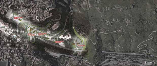
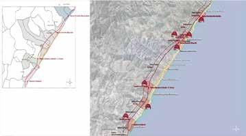
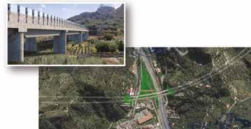
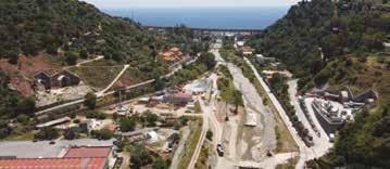
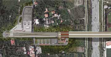
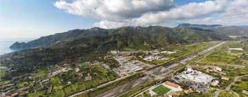
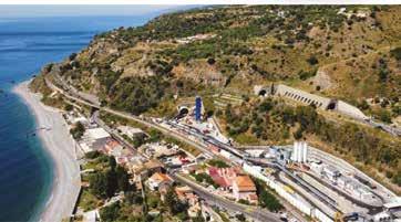
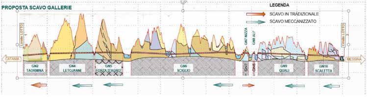
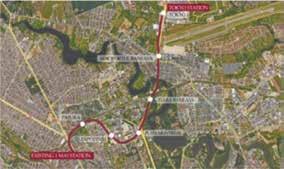
ARX è coinvolta nella progettazione su tutti i lotti della Direttrice Ferroviaria Palermo-Catania-Messina e ogni galleria della linea ha le sue peculiarità. La galleria Trinacria del lotto 4a della Palermo-Catania, scavata in meccanizzato a doppia canna, solo per citare la galleria su cui sono maggiormente coinvolta, ha una lunghezza di 13,5 km e sottoattraversa la città di Enna con una copertura di quasi 600 m attraversando le formazioni dei Gessi di Pasquasia, delle marne argillose della formazione Tripoli e delle argille della formazione Terravecchia: un bel progetto, per niente semplice, su cui di sicuro ci sarà molto da imparare e da scrivere nei prossimi anni. Per fortuna possiamo contare sull’ottima sinergia che c’è tra Cliente, Impresa e Progettista che permette di approfittare della considerevole esperienza dei tanti tecnici coinvolti su questi progetti. In questi ultimi anni finalmente l’Italia è diventata il posto dove si sviluppano alcuni tra i progetti più interessanti della nostra industria, tanto da diventare attrattiva anche per quanti hanno trascorso gli ultimi anni seguendo delle talpe all’estero.
Quali consigli daresti a chi, oggi, vuole intraprendere un percorso simile al tuo?
In realtà non credo ci siano consigli da dare, ogni storia è a sé. Credo che sia importante non smettere mai di essere curiosi e non sentirsi mai arrivati e considerare ogni nuovo progetto come un nuovo inizio professionale.
Grazie Stefania, prima di salutarti vorremmo esprimerti le nostre congratulazioni per il tuo recente incarico di consigliere della SIG. Cosa vuol dire per te questa nomina?
E’ un incarico che ho accettato con grande entusiasmo, per me è un onore rappresentare ARX all’interno della SIG e potermi confrontare con colleghi di grande esperienza e di grande valore. Ho trovato un ambiente stimolante, con una grande voglia di fare bene per l’associazione e soprattutto una grande volontà di ispirare chi opera nel nostro settore e condividere esperienza e know how nella nostra industria. Spero davvero di dare un contributo utile alla SIG e ai Working Groups in cui sono stata chiamata ad operare.
La stazione Brooklin a San Paolo, Brasile.
Tipica Yurta Mongola.
In occasione del convegno SIG “Risk management and contractual aspects in underground works”, svoltosi il 1° ottobre scorso nell’ambito di Expo-ferroviaria a Milano Rho Fiera, gli ingegneri Matthias Neuenschwander e Hannes Ertl hanno presentato una relazione sull’Emerald Book FIDIC-ITA e sulle sue principali procedure applicative. Il tema è stato poi approfondito in una tavola rotonda moderata dall’avv. Luca Puletti e dall’ing. Agostino Viglione. Per l’elevato interesse tecnico e l’attualità degli argomenti trattati, la Redazione ha invitato i relatori a trasformare i loro interventi in contributi scritti. I due articoli scientifici che seguono, sottoposti a peer review, sono preceduti da questo testo introduttivo dell’avv. Luca Puletti, che ne inquadra efficacemente i contenuti.
Verso una contrattualistica collaborativa per
le grandi
opere infrastrutturali: l’evoluzione tra rischio geotecnico, standard FIDIC e modelli innovativi di alleanza
Ghella S.p.A.; Mail: lpuletti@ghella.com
Negli ultimi anni il settore delle infrastrutture complesse, in particolare delle opere in sotterraneo, ha assistito a un’evoluzione significativa nella gestione contrattuale e nella ripartizione del rischio. A livello internazionale, la FIDIC – Federazione Internazionale degli IngegneriConsulenti – ha posto le basi per una standardizzazione più efficace con la pubblicazione dell’Emerald Book, redatto congiuntamente all’ITA, che ha introdotto il Geotechnical Baseline Report (GBR) come strumento chiave per la gestione e allocazione dei rischi geotecnici. Nel tentativo di ridurre le controversie e aumentare l’efficienza nella realizzazione dei progetti, si stanno diffondendo modelli contrattuali collaborativi – come l’Alliance Contract e i Target Cost Contracts – che puntano su trasparenza, condivisione dei rischi, incentivi basati sulle performance e risoluzione consensuale delle controversie. Esperienze recenti, come l’appalto per il prolungamento della linea 1 della metropolitana di Milano, testimoniano l’applicazione concreta di queste logiche innovative, in un contesto in cui il rapporto tra pubblico e privato è sempre più orientato alla cooperazione strutturata e alla prevenzione del contenzioso.
In parallelo, anche in Italia è possibile intravedere un progressivo processo di aggiornamento normativo e contrattuale, recepito nel nuovo Codice dei Contratti Pubblici (D.Lgs. 36/2023), che riconosce le condizioni geologiche impreviste come causa di variante, pur senza prevedere automatismi nei riconoscimenti economici. A supporto della prevenzione e risoluzione delle controversie, lo stesso Codice ha introdotto il Collegio Consultivo Tecnico (CCT), un organismo imparziale e qualificato, ispirato ai Dispute Boards internazionali, pensato per accompagnare le parti durante l’esecuzione dei lavori, facilitando soluzioni rapide e tecniche ai potenziali conflitti.
In questo nuovo scenario, la cultura del “contendere” lascia gradualmente spazio a modelli collaborativi, basati sulla trasparenza, la condivisione del rischio e l’allineamento degli obiettivi tra tutte le parti coinvolte. Un cambio di paradigma che potrebbe rappresentare la chiave per migliorare tempi, costi e qualità nella realizzazione delle grandi opere italiane.
Un contributo importante in questa direzione arriva dalla Società Italiana Gallerie (SIG), che ha recentemente pubblicato due documenti fondamentali: “Gestione del rischio ed aspetti contrattuali nelle opere in sotterraneo” e “Il meccanismo del time adjustment per lunghe gallerie transfrontaliere italiane”. Questi testi offrono un inquadramento tecnico-normativo aggiornato per affrontare le complessità delle opere in sotterraneo, con particolare attenzione alla definizione delle condizioni geotecniche e alla necessità di garantire un’equa distribuzione dei rischi tra Committente e Appaltatore.
Verso un nuovo paradigma
In sintesi, si profila un cambio di paradigma per la contrattualistica delle grandi opere in sotterraneo in Italia: da modelli tradizionali basati su rigidità e sulla gestione reattiva dei problemi, verso approcci più adattivi, cooperativi e trasparenti. L’unione tra meccanismi come il GBR e l’Emerald Book, modelli collaborativi come Target Cost e Alliance Contract, e istituzioni di garanzia e risoluzione preventiva come il Collegio Consultivo Tecnico, potrebbe offrire una strada efficace per contenere i rischi, migliorare le performance, ridurre i conflitti e rendere le opere più sostenibili sotto il profilo dei tempi, dei costi e della qualità.
Avv. Luca Puletti
Risk management and contractual aspects in underground works: an introduction to the Emerald Book
Gestione del rischio e aspetti contrattuali nelle opere sotterranee: un’introduzione all’Emerald Book
Matthias NeueNschwa Nder a
Hannes ertlb
a Neuenschwander Consulting Engineers SA, Bellinzona, Switzerland
b Vista Perfecta Consulting&Mediation, Drvenik Veliki, Croatia
Abstract
Underground works differ from other works mainly because of the need to create and secure an empty space in a ground mass, the knowledge of which is intrinsically imperfect. Excavation and lining of this space are therefore an important part of the scope of the works, and have a strong impact on feasibility, time for completion and cost. The FIDIC-ITA Emerald Book addresses this peculiarity and proposes effective tools for contractual allocation of the risks to each party, efficient contract management, reduction of scope for disputes and enhanced cost stability.
Sommario
I lavori sotterranei si distinguono in particolare per la necessità di creare uno spazio vuoto in un materiale naturale, le cui caratteristiche, intrinsecamente, sono note in maniera imperfetta. Lo scavo e il rivestimento di tale spazio sono pertanto parte importante dell’opera, e hanno un impatto forte sulla fattibilità, il tempo di realizzazione e il costo. L’Emerald Book di FIDIC e ITA-AITES considera questa particolarità, e propone approcci efficaci per l’allocazione dei rischi a ciascuna delle parti, una gestione efficiente del contratto, la riduzione di dispute ed una accresciuta stabilità dei costi.
Keywords: Emerald Book, gestione dei rischi, GBR, prevenzione e risoluzione di dispute, contratti d’appalto per il sotterraneo. Parole chiave: Emerald Book, Risk management, GBR, Dispute Avoidance and Adjudication, Underground Works Contracts.
1. Introduction
“Contract” has its origin in the Latin verb “con-trahere”, meaning “pull together”. Hence, “contractus” means an entity of various items or subjects brought together. The concept of formalizing (amongst others) personal, commercial or political relationships between different parties is ancient and universal, having been in use in ancient China [1] as well as in pre-Christian Europe [2] or in pre-Aztec Latin America. Contracting is a well rooted, trans-cultural way of regulating many kinds of relationships. People across the world are used to contracting, and the construction (and, within construction, the sub-surface construction) community is
but a sample of “contractors” (in the sense of individuals or entities that enter into contracts). The largest part of a subsurface construction contract will have to satisfy the same needs as any construction contract and actually, as many other contracts.
A contract regulates the commitments of the contracting parties and the rights that result from these commitments in a given cultural, social and legal framework. Its validity depends on the context at its origin: a change in context may influence the capability of the parties of respecting their commitments and may therefore also affect their respective rights.
The essence of a contract that goes beyond specifying the
rights and onus of the parties in a given context is that it sets the rules for adaptation to changes in context. We suggest using the term “robust” to define a contract that sets such rules in a way that they are a) regularly used and b) enforceable.
The scope of this paper is not a treaty on robustness of contracts at large. We shall therefore limit our efforts to trying to answer the question what makes the difference of a “robust” contract in sub-surface construction.
One possible definition of sub-surface or underground Works is the definition given in the Emerald Book [3]: “ Underground Works means all Works located beneath the natural or man-made surface of the earth, including ancillary surface works ”. The definition should be even more restricted, as it essentially refers to construction works, meaning works that include the creation of a space (a void) below the surface of the earth to be used for multiple purposes (e.g., transportation facilities for vehicles, fluids or utilities, stocking of goods, cinemas, hospitals or electric power plants, etc.).
The ultimate scope of underground works therefore does not explicitly include the creation of a safe empty space that can be used. However, it is this very act that mainly distinguishes underground works from all other works: the creation of a sub-surface void with a stable and durable hull, or, as constructors would say, the “excavation and lining” of the subsurface space.
2. About contracts for underground works
2.1. Effect of the excavation and lining on the project
The creation of the void and its hull is preliminary to all other activities in the sub-surface project. Any change in the effort it takes to excavate and line the void may therefore have an impact on some or all other parts of the works, including the “Time for Completion”, the final cost and, in some cases, the scope. This is the main difference between underground works and most other categories of works (similar boundary conditions may occur, e.g. in works on or under the sea, in works with extreme climate conditions, etc.). We shall therefore concentrate on changes in the effort it takes to excavate and line the underground empty space to be created.
2.2. “Robustness” of a contract for underground works
A robust underground works contract should particularly address the potential changes in ground and environmental conditions that affect effort for excavation and lining against the initially foreseen conditions that were the basis for the contract, and it should provide effective and efficient rules and tools for adaptation of the onus and rights of the parties to such changes. The more effective these rules and tools are, the less energy (and time and money) will be lost in disputes.
2.3.
About risks that are peculiar to underground works
As said above, the realization of any underground works requires the excavation and lining of the necessary space. Even with appropriate investigations, it is practically impossible to exactly know the characteristics of the ground to be excavated and supported. The main uncertainty to add in underground works to all other uncertainties that may be part of a project is therefore the nature of the ground to be excavated and lined, or, rather, the effect of the nature of the ground on the effort required in energy, time and cost to excavate and line the required space.
This uncertainty entails the main risk related to underground works and other geotechnical works as opposed to all other works, and should therefore be mitigated to the extent possible.
The “nature of the ground”, as understood by the authors, includes, without limitation:
– geo-mechanical and geotechnical characteristics,
– all groundwater related phenomena,
– conditions of gas,
– natural or man-made obstacles,
– induced loads from the ground or from structures above or nearby,
– potential of damage to nearby infrastructures or buildings,
– potential of use of the excavated spoils, – etc.
The “effect of the nature of the ground on the effort required … to excavate and line the required space”, as understood by the authors, includes, without limitation, – the choice of excavation and lining methodology and equipment,
– the measures to stabilize the ground around the excavated space,
– the measures to solve the groundwater and gas related difficulties, – the measures to overcome obstacles, – the measures to avoid damage to nearby infrastructures or buildings, – the measures to treat, recycle or dispose of the spoils, – the measures to further investigate the ground during construction in order to optimize the above measures, – etc.
Any change in the nature of the ground as foreseen in the contract, should therefore entail an adaptation of the contract only insofar as it impacts the effort it takes to excavate and line the required space. Of course, such an impact on the effort it takes to excavate and line the required space may have consequences on other aspects of the works like, e.g., delay of subsequent parts of the works, changes in the critical path, etc. Such consequences should also be considered.
Table 1. Preliminary steps to a contract.
Step Responsibility
Signature of Contract
Award
Both parties
Owner/Employer
Bid Contractor
Tender
Owner/Employer
Pre-tender investigations and design Owner/Employer
Procurement strategy
Assessment of requirements and preliminary studies
2.4. Prior to the contract, the tender
Owner/Employer
Owner/Employer
The contract is the result of a chain of preliminary actions by the parties. Counting backwards from the contract signature, we may distinguish the following steps (Tab. 1).
The bid of the contractor will depend on the owner’s tender, which in turn depends on the pre-tender design/investigations and on the procurement strategy. It is ultimately the owner’s procurement strategy that determinates the contract. For the contract to be robust (in the sense of the introduction to this paper), all preliminary steps must be carried out with competence and diligence. In the following, we shall take a closer look at the pre-tender activities by the owner (post assessment of requirements, preliminary studies and procurement strategy).
3. Planning & Preparation
3.1.
Early Risk Identification
Effective risk identification in underground works requires both comprehensive site investigations and interpretation and modelling procedures, and further a structured stakeholder engagement. Detailed desk studies, field testing, and laboratory analyses are essential to establish a reliable ground model, thereby facilitating the anticipation of geotechnical hazards such as weak strata, groundwater ingress, or chemically aggressive conditions. Complementing this technical foundation, risk workshops that bring together clients, designers, contractors, geologists, and other relevant stakeholders enable a systematic consideration of risks extending beyond ground conditions, including technical, environmental, financial, contractual, and safety dimensions. The outcomes of these workshops may be formalized in risk registers, in which each risk is described, assessed in terms of likelihood and impact, allocated, and accompanied by proposed mitigation measures, thereby promoting proactive and transparent risk management throughout the project lifecycle.
3.2. Use of Predictive Tools
Predictive tools such as enhanced geomodelling, numerical modeling, probabilistic analysis, and scenario planning
support early risk identification in underground works by simulating soil and rock behavior, assessing the impact of uncertainties by performing sensitivity analyses, and preparing for best, expected, and worst-case ground conditions.
3.3. Early Risk Allocation
The principle: allocate each risk to the party best able to manage, control, or bear it at least cost.
Clear allocation of responsibilities between the client/employer and the contractor is fundamental to effective risk management in underground construction projects. By explicitly defining obligations in relation to ground conditions, environmental challenges, construction methods, and external influences, contracts can reduce disputes, foster collaboration, and ensure that risks are borne by the party best able to manage them [4].
The following outlines the principal responsibilities typically assigned to the client/employer and the contractor.
3.4. Client/Employer Responsibilities
The client/employer shall provide adequate and reliable site information to support project planning and execution. This typically includes the supply of factual ground investigation reports and, where applicable, a geological baseline report that defines expected conditions relevant to the construction method to be used. The employer is generally responsible for risks arising from unforeseen ground or groundwater conditions that exceed contractual predictions, often managed through cost-sharing formulas. Further responsibilities extend to environmental risks including contamination or settlement impacts, to securing necessary permits and approvals, ensuring compliance with environmental and regulatory frameworks, and establishing agreements with affected communities and stakeholders to facilitate smooth project delivery. In addition, force majeure events such as earthquakes or extreme floods shall be considered.
3.5. Contractor Responsibilities
The contractor, by contrast, is primarily responsible for the detailed design, means and methods of construction, ensuring that equipment and operations, such as, e.g., tunnel boring machine (TBM) performance, are fit for purpose and effectively managed. Responsibilities also encompass the implementation of rigorous safety and quality management systems to safeguard workers, the public, and the constructed works. Within the scope of the “baseline conditions” defined in the contract, the contractor is expected to manage and mitigate associated risks through appropriate construction practices and technical expertise. This allocation ensures that contractors are accountable for aspects under their direct control while protecting them from bearing undue responsibility for risks outside the agreed baseline or beyond their reasonable capacity to manage.
3.6. Tools for Effective Early Allocation
Effective early risk allocation in underground works relies on clearly defining expected conditions and responsibilities before construction begins. Tools such as the Geotechnical Baseline Report (GBR) provide a contractual benchmark for anticipated ground conditions, while “Differing Site Condition” (DSC) or “Unforeseeable Physical Condition” (UPC) as suggested by [5] for example.
Such clauses allow contractors to claim additional time and/ or cost if actual conditions deviate significantly. Risk registers document each risk, its potential impact, mitigation measures, and assigned owner, promoting transparency and accountability [6]. Together, these measures help minimize disputes, support fair cost allocation, and enable proactive management of uncertainties inherent in underground construction.
3.7. Benefits of early risk identification & allocation
Early risk identification and allocation provide significant benefits to underground works projects by creating clear expectations between stakeholders. When risks are recognized and assigned to the party best able to manage them, disputes are reduced, contractors avoid inflating bids with excessive contingencies, and safety is improved through proactive hazard planning. This clarity fosters greater collaboration and trust, leading to more predictable costs, stable schedules, and overall smoother project delivery.
In short: early risk identification relies on thorough investigations and structured risk registers, while early allocation depends on transparent tools like the GBR, DSC clauses, and collaborative contract models. Done properly, it contributes to preventing cost overruns and disputes.
3.8. Clear Definition of Scope & Interfaces
A fundamental requirement for the success of underground construction projects is the clear definition of project scope at an early stage. Underground works are often executed within densely built environments or as part of complex multi-package infrastructure programs (e.g., metro systems, underground stations, and utility diversions). In particular in such contexts, ambiguity in scope can lead to overlapping responsibilities, gaps in deliverables, and disputes between stakeholders. Clearly documenting the extent of works—such as tunnel alignment, excavation methods, support systems, lining design, and temporary works—provides a baseline against which performance, risk allocation, and costs can be managed. A fine guide to management by design may be found here [9].
Equally important is the precise definition of interfaces between different contracts, disciplines, and stakeholders. Underground works frequently interact with surface construction (stations, ventilation shafts, portals), existing utilities, and third-party assets (railways, highways, or bu-
ildings). If these interfaces are not identified and assigned properly, risks such as service clashes, schedule delays, and safety hazards may arise. For instance, defining whether the tunnel contractor or the station contractor is responsible for waterproofing at the junction is critical to avoid costly rework or disputes.
Best practice involves preparing Interface Control Documents (ICDs) and detailed scope breakdown structures during design and procurement. These documents set out the limits of work for each party, technical handover requirements, and testing/commissioning responsibilities. Contractually, scope and interface clarity is reinforced through well-defined specifications, drawings, and schedules.
Ultimately, the clear definition of scope and interfaces is an effective risk management measure and a contractual safeguard. It reduces the likelihood of disputes, facilitates smoother coordination between packages, and enables the project team to focus on managing genuine uncertainties such as ground conditions rather than contractual ambiguities.
3.9. Adequate Site Investigation & Geotechnical Baseline Reports (GBR)
One of the most critical factors in underground construction projects is the adequacy of site investigation. Unlike surface works, where conditions can be observed directly, underground projects face high uncertainty due to the concealed nature of the ground. A poor understanding of subsurface conditions often leads to unexpected challenges such as excessive groundwater inflows, unstable ground, or obstructions, which in turn can cause significant cost overruns, delays, and disputes. According to [7] to mitigate this, comprehensive site investigations must be conducted early in the project lifecycle and updated progressively as design and construction advance. An adequate site investigation typically includes a combination of desk studies, geological and hydrogeological mapping, borehole drilling, in-situ testing, laboratory testing, geophysical surveys, and – in the most challenging projects – exploratory shafts / adits / galleries. The purpose is not only to identify soil and rock types but also to assess mechanical and hydraulic properties, fault zones, discontinuities, voids, chemical aggressiveness, and variability in conditions along the proposed alignment. The quality and coverage of site investigations directly influence the reliability of the ground model and therefore the accuracy of risk assessments, design solutions, and tender pricing [8].
The Geotechnical Baseline Report (GBR) plays a central role in managing subsurface risks contractually. Unlike factual reports, which present raw investigation data, the GBR defines the baseline ground conditions that the contractor can expect for pricing and planning purposes. It becomes a con-
Risk management and contractual aspects in underground works…
tractual reference point for distinguishing between expected and differing site conditions. If actual conditions encountered during construction deviate from those defined in the GBR, the contractor may be entitled to compensation for additional cost and time.
The use of a well-prepared GBR offers several advantages. It encourages contractors to bid competitively based on a shared understanding of ground risks, reduces the tendency to inflate prices with excessive contingencies, and minimizes disputes over ground condition claims. International best practice, reflected (without limitation) in the FIDIC Emerald Book (2019) [3] and the ITA Contractual Framework Checklist for Subsurface Construction Contracts [10], emphasizes the GBR as a key tool for risk allocation in underground works. Ultimately, adequate site investigations coupled with a robust GBR are part of the foundation of both technical risk management and contractual fairness in tunneling projects.
4. Procurement strategy
4.1. Clarify the funding model and the Owner’s organization
In underground construction projects, early clarification of the funding model and the structure of the owner’s organization is essential for transparency, risk management, and overall project success. Underground works are typically high-value, long-duration, and technically complex, often requiring financing from a combination of sources such as public budgets, loans from multilateral development banks (MDB), private equity, or publicprivate partnerships (PPPs). Each funding model brings specific requirements and constraints. For example, MDB-financed projects demand strict adherence to procurement guidelines, while PPP models may require longterm performance guarantees and integrated operation periods. Clearly defining the funding model at the outset enables contractors to better understand the financial environment, payment security, and potential risk-sharing mechanisms.
Equally important is clarifying the owner’s organizational structure. Large underground projects involve multiple stakeholders, including government agencies, financiers, engineers, and contractors, making it vital to establish clear lines of authority and decision-making. A transparent organizational framework helps contractors identify who is responsible for approvals, variations, and dispute resolution, reducing the risk of delays and misunderstandings. Clear definition of the owner’s roles, responsibilities, and resources enhance confidence among bidders, improve communication, and support efficient contract administration. In practice, clarity in both funding and organizational arrangements fosters trust between parties and contributes to smoother project delivery in the inherently uncertain environment of underground works.
If the funding model and the owner’s organizational structure are not clearly defined, underground projects often face significant challenges. Uncertainty in financing can lead to delayed payments, interruptions in cash flow, and in severe cases, project suspension problems that are particularly damaging in tunnelling, where work must progress continuously to maintain stability and safety. Likewise, organisational issues within the client’s organisation (such as insufficient staffing, unclear roles, lack of competence, insufficient level of delegation, insufficient technical advisory, etc.) may cause slow decision-making on design changes, variations, or claims, leading to disputes and schedule overruns. Fragmentation of responsibilities between different agencies or stakeholders can also result in conflicting instructions and inconsistent risk management. These issues not only increase project costs but also undermine contractor confidence and discourage competitive bidding. Clear upfront definition of funding and governance arrangements is therefore not only good practice but also a key risk mitigation measure in underground construction.
4.2. Select the appropriate Contract Form
In the following, a series of widely used forms of contract are listed. They may be used subject to national legislation and contract practice.
1) FIDIC (International Federation of Consulting Engineers)
The FIDIC suite of contracts is one of the most widely used international standard forms for construction and engineering projects, including underground works. Their key strength lies in their global recognition and adaptability, offering a common contractual language for cross-border projects. FIDIC contracts promote fairness and balanced risk-sharing while also providing mechanisms such as Dispute Adjudication/Avoidance Boards (DABs/ DAABs) to resolve issues efficiently. Overall, FIDIC contracts serve as an internationally accepted baseline for construction agreements, valued for their clarity, balance, and global applicability. The following contract types are tailored for specific procurement types:
a) Red Book – Construction (employer-designed works, remeasurement) [11]
The Red Book is the oldest FIDIC form, widely used for projects where the design is provided by the employer and the contractor executes the works. It is best suited for building and civil engineering projects where specifications are clearly defined. Its strengths lie in clear risk allocation, well-established procedures for variations and payments, and its broad acceptance worldwide. The Red Book does not include specific tools for underground works.
b) Yellow Book – Plant & Design-Build [12]
The Yellow Book shifts more responsibility to the con-
tractor, who undertakes both design and construction. It is suited to projects where performance-based outcomes are required, such as plants, process works, and infrastructure involving complex engineering systems. Its key strength is integrating design and construction under a single contractor, which can streamline delivery and reduce interface risks. However, this also places greater design and performance risk on the contractor, which can increase bid prices and lead to disputes if project requirements are not well defined. The Yellow Book does not include specific tools for underground works.
c) Silver Book – EPC/Turnkey
The Silver Book is tailored for Engineering, Procurement, and Construction (EPC) or turnkey projects, where the contractor delivers a fully operational facility at a fixed price and date. It places all risk on the contractor. As per its own introductory notes, this contract form is not suitable for underground works.
d) Gold Book – Design-Build-Operate
The Gold Book is an extension of the Yellow Book to include a long-term operation and maintenance period, making it suitable for infrastructure or building projects, such as e.g., water treatment plants or toll bridges.
e) Emerald Book – Underground Works [3]
The Emerald Book, developed jointly with the International Tunnelling Association (ITA), is specifically tailored to underground construction projects. It introduces the Geotechnical Baseline Report (GBR) as a contractual tool to clearly define ground condition risks and establish fair risk-sharing mechanisms. Its strengths include addressing the high uncertainty of subsurface conditions, providing structured procedures for variations, and enhancing collaboration in risk management. The Emerald Book represents a significant advancement in adapting standard contracts to the specific challenges of tunnelling.
2) NEC (New Engineering Contract) [13]
The NEC4 Engineering and Construction Contract (ECC), widely used in international infrastructure projects, emphasizes collaboration, flexibility, and proactive risk management. It is supported by guidance documents tailored to underground works, including the International Tunnelling Association (ITA) guidelines for preparing a Geotechnical Baseline Report (GBR) for NEC4 contracts. Options B and D, which incorporate a bill of quantities, provide structured approaches for pricing and managing variations while maintaining transparency in risk allocation. The strengths of NEC4 lie in its emphasis on early warning mechanisms, joint risk management, and clarity of communication, which help to minimize disputes and promote efficiency. Furthermore, the inclusion of a GBR in line with ITA gui -
dance enhances geotechnical risk allocation by providing a clear contractual reference for subsurface conditions. Its effectiveness relies on experienced project teams and disciplined implementation.
3) Austrian ÖNORM B 2110, B2203-1 and B2203-2 [14]
The Austrian standards for construction and underground works, particularly ÖNORM B 2110, B 2203-1, and B 2203-2, provide a structured framework for managing contractual, technical, and safety aspects of tunnelling projects. ÖNORM B 2110 establishes clear rules for handling variations, unforeseen conditions, and claims, while promoting proactive project management, early warnings, and flexible contracting strategies. Its main advantage lies in reducing disputes and fostering collaboration; however, it relies heavily on experienced contract administration and can be complex for smaller contractors. Complementing this, ÖNORM B 22031 sets out general provisions for underground works. Finally, ÖNORM B 2203-2 provides detailed guidance on drill-and-blast tunnelling, covering blasting design, execution, monitoring, and documentation. The Ö-Norm B 2203-1, together with the Swiss standard 118/198, has been a benchmark standard in the development of the FIDIC Emerald Book.
4) Swiss SIA 118 and 118/198 [15]
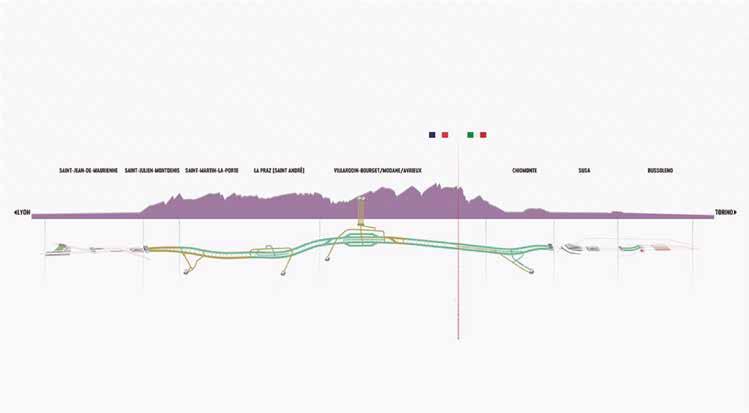
The Swiss SIA 118 and 118/198 conditions of contract are the contract standard in Switzerland for underground works contracts. They place strong emphasis on fairness, balanced risk allocation, and dispute prevention. The framework clearly regulates ground risk allocation, time and price adjustment, variations, payments, and defect liability, while also promoting collaborative problem-solving between client and contractor. Its detailed structure may limit flexibility compared with more performance-based or internationally adaptable models, requiring adaptation in international contexts. Overall, SIA 118/198 offers a fair and dispute-preventive contractual basis that supports efficient project execution and has proven adaptability, e.g. in the french-italian railway base tunnel and, together with the Ö-Norm B2203-1, as a benchmark standard in the development of the FIDIC Emerald Book.
5) German VOB/B [16]
The German VOB/B (Verdingungsordnung für Bauleistungen – Part B) serves as the standard set of contractual terms for construction projects in Germany, including underground works. It provides a comprehensive legal framework governing payments, variations, defect liability, and contractual obligations between clients and contractors. Its strengths lie in the high level of legal certainty and its long-established role within the German construction industry, which ensures familiarity among stakeholders and consistent judicial interpretation. For underground works,
Risk management and contractual aspects in underground works…
the VOB/B offers detailed provisions for dealing with variations and defects, thereby supporting quality assurance and risk allocation.
6) ICC (International Chamber of Commerce) Model Contracts [17]
The ICC (International Chamber of Commerce) Model Contracts provide internationally recognized standard forms designed to promote balanced risk allocation and fair contractual practices across a wide range of construction projects, including underground works. While not specifically tailored to tunnelling, they offer a flexible framework that can be adapted to complex subsurface conditions by incorporating project-specific technical annexes, risk-sharing provisions, and geotechnical documentation.
7) World Bank / Multilateral Development Bank Standard Procurement Documents [18]
The World Bank and other Multilateral Development Banks (MDBs) have developed Standard Bidding Documents (SBDs) to ensure fairness, transparency, and consistency in the procurement of large infrastructure projects, including underground works. These documents are closely aligned with FIDIC contract forms, particularly the Red and Silver Books, but include MDB-specific provisions to address financing, eligibility, and anti-corruption requirements. For tunnelling projects, the SBDs provide a structured framework for tendering and contract execution, offering clear rules on scope, payment, and dispute resolution.
The World Bank has expanded its licensing agreement with FIDIC to include the Emerald Book (Conditions of Contract for Underground Works, First Edition 2019) as part of its Standard Bidding Documents (SBDs) for all underground works in World Bank financed projects.
8) JCT (Joint Contracts Tribunal – UK) [19]
The JCT (Joint Contracts Tribunal) suite of contracts, widely used in the United Kingdom, provides a structured framework for construction projects, including underground works. Its focus lies on clearly defined roles, responsibilities, and procedures for payments, variations, and defect management, offering a high level of contractual certainty. For tunnelling and underground projects, JCT contracts can be adapted to include geotechnical risk provisions, method statements, and technical annexes, though they do not contain sector-specific tunnelling rules.
9) AIA [20]/ EJCDC [21] (North America)
In the United States, the most commonly used contractual framework for underground and tunnelling works is the EJCDC (Engineers Joint Contract Documents Committee) suite of contracts and, for large-scale projects, the Design-Build model under DBIA (Design-Build Institute of America) contracts. In addition, federally funded projects often follow Federal Acquisition Regulations
(FAR) or adaptations of AIA (American Institute of Architects) contracts. For underground works in particular, the EJCDC Construction Series (C-series) is the most widely applied.
10) Bespoke / Hybrid Contracts
In the tunnelling industry, bespoke and hybrid contracts are frequently adopted to address the unique risks and complexities of subsurface works that standard forms may not fully capture. Their main advantage lies in the high degree of flexibility they offer, allowing parties to tailor contractual provisions to the technical and geotechnical challenges of a given project. Hybrid arrangements, however, may create inconsistencies or conflicting provisions if not carefully drafted. Overall, bespoke and hybrid contracts offer a powerful means of tailoring risk allocation and management to the realities of tunnelling projects, but their benefits of flexibility and precision are offset by higher transaction costs, complexity, and potential legal uncertainty.
4.3. Prequalification of Contractors
Prequalification is a critical stage in the procurement of underground works, ensuring that only suitably experienced and capable contractors are invited to tender. Tunnelling projects demand highly specialized technical knowledge, advanced equipment, and proven experience in managing geotechnical risks, which distinguishes them from more conventional construction works. Effective prequalification criteria typically include demonstrated experience with comparable underground projects, availability of qualified personnel, financial capacity, safety performance, and a track record of delivering complex works on time and within budget. Technical references, such as the ITA guidelines [3], emphasize the importance of assessing contractors’ ability to deal with variable ground conditions, implement robust health and safety systems, and manage sophisticated monitoring technologies.
The benefits of a thorough prequalification process are twofold: it reduces the risk of contractor failure during project execution and ensures a more reliable competition among bidders who possess the requisite expertise. This enhances overall project quality and provides greater assurance to clients and financiers. In underground projects, where unforeseen conditions and technical risks are significant, wellbalanced prequalification serves as a vital risk management tool by aligning project complexity with contractor capability.
4.4. Transparent and Competitive Tender Procedures
Transparent and competitive tendering is essential for ensuring fairness, accountability, and value for money in underground construction projects, many of which involve substantial public investment. A transparent process requi-
res clear and comprehensive tender documentation, equal access to information for all bidders, and the consistent application of evaluation criteria. For underground works, this means providing design information, geotechnical data, and ground baseline reports (GBRs), along with clearly defined risk allocation clauses.
Competitive tendering encourages innovation and efficiency by enabling capable contractors to propose optimized construction methods, equipment, and sequencing. However, there are potential drawbacks: highly competitive environments can encourage underpricing, which later translates into claims, disputes, or compromised safety. Therefore, tender procedures should aim at price AND quality-based awards.
5. Tender Documentation
Well-prepared tender documentation is a cornerstone of successful underground construction projects, as it sets the contractual, technical, and managerial framework for project execution. Clear and comprehensive documents not only support fair competition during tendering but also facilitate smooth project delivery by reducing ambiguities and disputes.
5.1.
Scope
A clearly defined project scope is essential for effective tendering. A well-prepared scope of works ensures smooth contractor selection by allowing bidders to understand the project requirements and propose realistic methodologies. It also simplifies subsequent contract management by reducing uncertainties and ambiguities. Furthermore, precise scope definition supports cost stability by limiting the risk of claims and variations resulting from unclear responsibilities or overlapping tasks.
5.2. Technical Specifications and Design Information
Tender documents must provide detailed technical specifications and design information tailored to underground works. This may include excavation methods, support systems, lining requirements, and performance criteria for materials and equipment. The level of detail should balance prescriptive requirements with performance-based criteria, allowing room for contractor innovation while ensuring that minimum safety and quality standards are met. Incomplete or vague technical specifications can lead to disputes, inefficiencies, and compromised quality.
5.3. Ground Conditions and Risk-Sharing Clauses
Given the inherent uncertainty of subsurface works, tender documents should include comprehensive geotechnical data and clear risk-sharing provisions. Ground investigation reports, baseline conditions, and geotechnical baseline reports (GBRs) provide bidders with reliable information to
prepare realistic offers. Equally important are clauses that fairly allocate risks related to unforeseen ground conditions between client and contractor.
5.4. Health, Safety, and Environmental Requirements
Underground works present significant safety and environmental risks, making health, safety, and environmental (HSE) provisions a critical element of tender documentation. Requirements should align with national regulations and international best practice, covering topics such as ventilation, emergency response, noise and vibration control, spoil management, and environmental monitoring as well as settlement control. Embedding these requirements at the tender stage ensures that contractors integrate safety and sustainability into their methods and pricing.
5.5. Time for Completion and Milestones
A realistic project timeline with defined milestones is another key component. Tender documents should specify the contractual completion date as well as intermediate milestones for critical activities, such as, e.g., tunnel breakthrough or lining completion. Unrealistic or vague timeframes, increase the risk of delay claims and cost escalation. In addition to these points, a flexible mechanism for time adjustments is critical for the smooth delivery of the project.
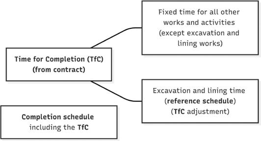
5.6. Price
Finally, tender documentation must establish the pricing structure and evaluation method. Whether based on a lump sum, unit rates, or bill of quantities, the pricing approach should reflect the project’s risk profile and ensure transparency in cost evaluation. Clearly defined rules for adjustments, escalation, and payment certification help maintain financial stability throughout the project. Transparent pricing frameworks also facilitate fair competition and allow the client to compare bids on a consistent basis.
6. Evaluation & Award
6.1. Balanced Technical and Commercial Evaluation
In underground works, the evaluation and award stage of tendering must balance both technical and commercial considerations. Unlike conventional surface projects, where costs and timelines are often more predictable, tunnelling involves high uncertainty in ground conditions, safety risks, and construction methodologies. A balanced evaluation framework ensures that tenders are not judged solely on price but also on technical merit, risk management strategies, safety standards, and innovation potential. This dual approach helps to identify bids that offer the best value for money over the project lifecycle, rather than simply the lowest initial cost. Such a Quality and Price-ba-
Risk management and contractual aspects in underground works…
sed award is crucial to ensure project delivery, cost stability and less scope for disputes.
This involves integrating risk-adjusted cost assessments, lifecycle cost considerations, and technical merit into the award decision. Mechanisms such as weighted scoring systems, two-envelope evaluations (separating technical and financial proposals), or negotiated procedures with clear safeguards can help strike the right balance. Technical evaluation typically includes assessment of proposed excavation methods, ground support systems, lining designs, and environmental protection measures. Commercial evaluation, meanwhile, ensures that proposed costs are realistic, sustainable, and aligned with the project’s financial model. Weightings between technical and commercial criteria vary, but good practice in tunnelling often gives significant weight to technical quality – sometimes as high as 80% – to ensure safety and constructability are prioritized. When evaluation criteria are transparently defined in the tender documentation, the process not only enhances fairness but also incentivizes bidders to propose innovative, technically sound, and efficient solutions.
Tunnelling is inherently complex, requiring tailored approaches to excavation, support, ventilation, and monitoring, which vary according to geology and project context. Therefore, evaluating the contractor’s proposed construction methodology provides insight into whether the tenderer has understood the project-specific risks and developed practical strategies to manage them.
Equally important is the contractor’s demonstrated experience in comparable projects. Experience in similar geological environments, project scales, or tunnelling techniques provides assurance of competence and reliability. Combining methodological soundness with proven experience reduces the likelihood of delays, claims, and safety incidents, while increasing the chances of robust and cost-effective solutions being applied.
7. Best contractual practices for underground works
Effective contractual management is essential in underground construction, where geological uncertainties, complex methods, and technical challenges can impact cost, schedule, and safety. Several good practices have emerged to enhance clarity, minimize disputes, and encourage innovation.
7.1. Clear risk allocation for unforeseen
ground conditions
A cornerstone of good practice is clearly defining responsibility for unforeseen ground conditions. Subsurface variability can significantly affect tunnelling operations, so contracts increasingly rely on Geotechnical Baseline Reports (GBRs) or
detailed site investigations to establish baseline conditions. Explicit definitions of what constitutes a changed condition, linked to risk allocation, reduce disputes and incentivize thorough investigation and early planning.
7.2. Dispute avoidance mechanisms
Even with clear risk allocation, disagreements may arise. Proactive dispute avoidance mechanisms, such as Dispute Resolution Boards (DRBs) and mediation, provide early intervention and advisory support. DRBs, composed of neutral experts, offer ongoing oversight, while mediation allows confidential, cost-effective resolution. These approaches maintain collaboration and project momentum, preventing escalation into adversarial legal proceedings.
7.3. Performance-based incentives
Contracts that include performance-based incentives encourage efficiency, quality, and innovation. Rewards tied to early completion, cost savings, environmental impact reduction, or novel construction methods align contractor and client interests. Such mechanisms, common in NEC4 and bespoke hybrid contracts, promote continuous improvement and motivate contractors to optimize tunnelling processes.
7.4. Change management and variation Procedures
Robust procedures for managing changes in cost and time are vital. Best practice requires structured submission, evaluation, and approval of variations, including timely notifications, agreed valuation methods, and integration with project schedules. Standard forms like FIDIC Emerald Book or NEC4 provide frameworks that ensure transparency and reduce disputes, while allowing agile responses to unforeseen conditions.
7.5. Conclusion
In sum, contractual good practices in underground works combine clear risk allocation, proactive dispute avoidance, performance incentives, and structured change management. Together, they balance risk, encourage collaboration, and support the safe, timely, and cost-effective delivery of complex tunnelling projects.
8. Condensation of the above in the FIDIC Emerald Book
The Emerald Book is a FIDIC Yellow Book with a toolkit for effectively addressing the peculiarities of underground works, while remaining a standard FIDIC form of contracts. Most of the Emerald Book’s content is identical to the Yellow Book, including in particular, the structure, number and titles of clauses and every aspect that is not related to the differences between underground works and other complex projects. It differs from a Yellow Book in only about 15% of its content and could therefore be used for other kinds of projects
that include minor geotechnical uncertainties (such as, e.g., a high-rise with a subsurface portion and/or challenging foundations). At the same time, the Emerald Book aims at improving underground works contracts so as to ensure better cost stability and less scope for disputes, through: – clarifying the ground related risk allocation between the Employer (the Owner) and the Contractor and – providing tools for addressing changes in the contract bases (not necessarily only ground related changes). As discussed above, the tender documents of the Employer should include information about the Employer’s foreseen construction methodology, based upon the Employer’s assessment of the site conditions (in underground works, this particularly includes ground conditions) and constructability studies. This information would be part of (in FIDIC language) the “Specifications”, the “Particular Conditions of Contract, Part 2” or the “Employer’s Requirements”, and may include a description of the construction methodology, specifications of TBM characteristics, ground support and/or lining cross sections etc.
In the FIDIC Yellow Book, the Employer’s Requirements have a lower contractual priority than the General Conditions of Contract (see Sub-Clause 1.5, “Priority of Documents). If the description of, e.g., the Employer’s preferred construction method, or subsurface physical conditions, were part of the Employer’s Requirements (or of a document with lower contractual priority), there would be a risk of their validity being jeopardized by a potential contradiction against the General Conditions of Contract. In order not to change the priority of documents in the Emerald Book against the Yellow Book, the authors of the Emerald Book (TG10) decided to allocate the information that is
crucial to calculating the effort (and therefore, time and cost) and assessing the risks related to the excavation and lining, in three documents that would have a higher priority than the General Conditions of Contract: the Completion Schedule, the Schedule of Baselines and the Geotechnical Baseline Report.
8.1. The Geotechnical Baseline Report (GBR) in the Emerald Book
The definition of the GBR in the Emerald Book goes beyond the definitions known from widely used literature, such as, e.g., the ASCE “Platinum Book”. It states:
The GBR shall include “design and construction methods, and the reaction of the ground to such methods”. These aspects have been consciously transferred into the GBR. Of course, in other contract systems and in some legal environments (e.g. Switzerland or Austria) this provision would not be necessary, because the Employer’s requirements would prevail over the General Conditions of Contract. This means that in an Emerald Book contract, crucial information on design and construction methodology shall be found in the GBR or in annexes thereof.
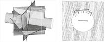
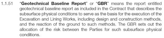
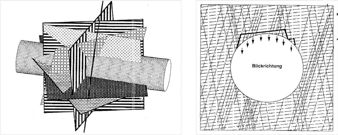
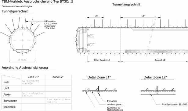
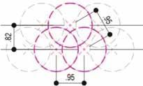
Example: from geological parameters to construction methods (Figs. 2-4).
Figure 1. Excerpt from the FIDIC Emerald Book SC 1.1 “Definitions”.
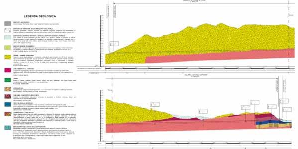
Figure 2. From geological mapping (left) to the risk scenario “wedging” (right) (excerpt from tender documents, Gotthard base tunnel, Switzerland).
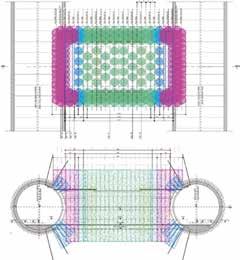
Risk management and contractual aspects in underground
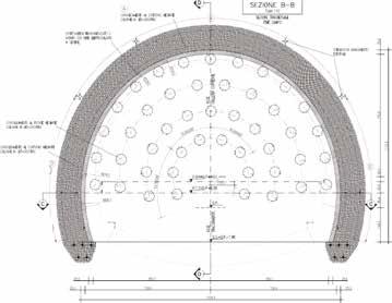
3. From risk scenarios to support scenarios to excavation classes (excerpt from tender documents, Gotthard base tunnel, Switzerland).
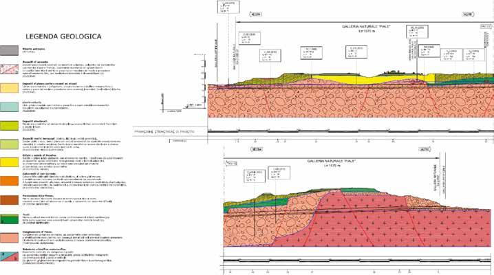
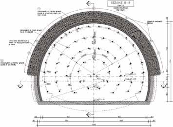
Figure 4. Definition of construction methodology according to risk scenario (excerpt from tender documents, Gotthard base tunnel, Switzerland).
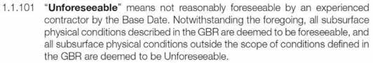
8.2. “Unforeseeable Physical Conditions” in the Emerald Book
The definition of “Unforeseeable Physical Conditions” explicitly refers to the GBR (Fig. 5).
The reference to “All subsurface physical conditions described in the GBR” shall therefore include the information
Figure 5. Excerpt from the FIDIC Emerald Book SC 1.1 “Definitions”.
Figure
Neuenschwander - Ertl
related to the design and construction methodology regarding the Excavation and Lining works, and the reaction of the ground to such methods.
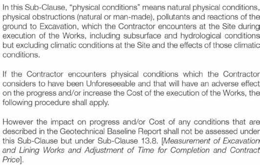
The consequences of encountering unforeseeable physical conditions are addressed in Sub-Clause 4.12 as follows:
Figure 6. Excerpt from the Emerald Book Sub-Clause 4.12 “Unforeseeable Physical Conditions”.
“Physical conditions” include “reaction of the Ground to Excavation”, and thereby clearly reference the GBR. Also, the third paragraph states that the impact of any conditions that are described in the GBR shall be assessed under the Measurement sub-clause 13.8.
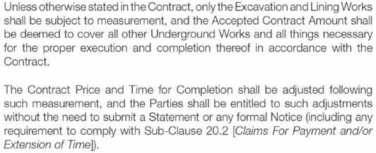
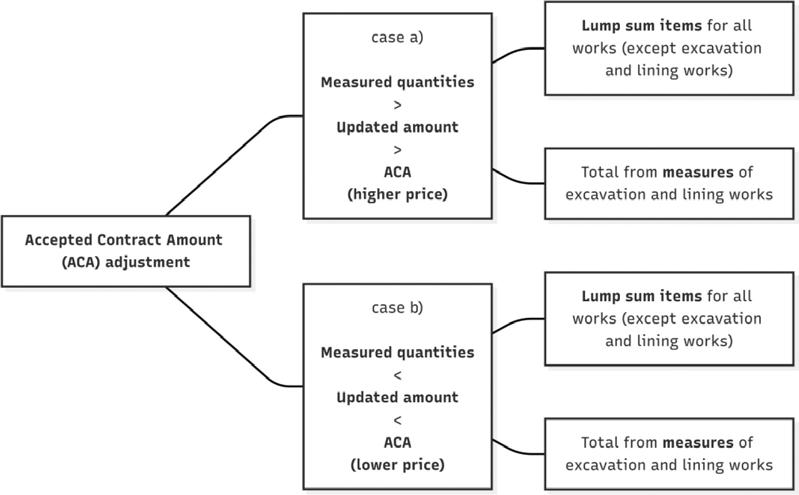
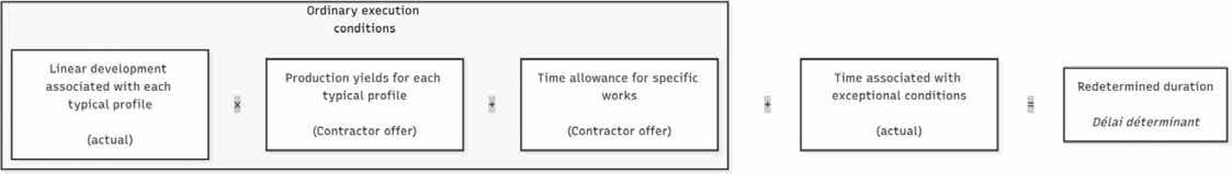
Figure 7. Excerpt from the Emerald Book, Sub-Clause 13.8 “Measurement of Excavation and Lining works and Adjustment of Time for Completion and Contract Price”.
As long as the Excavation and Lining methodology described in the GBR is sufficient to execute the works, it should therefore be possible to adjust the time and remunerate the cost and profit of the Contractor through measurement, without the need for a claim.
8.3. Avoid the need for claims: adjustment of Time for Completion and Contract Price by Measurement
Under the Emerald Book, the Time for Completion and the Contract Price of the Excavation and Lining Works shall be adjusted by measurement, in order to avoid the
need for claims in case of changes in quantities in, e.g., subsurface physical conditions that require different means and measures (and effort) to excavate and line parts of the works.
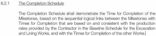
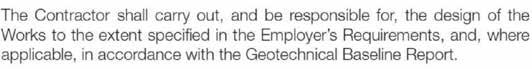
8.4. Defining and Adjusting the Time for Completion: the Completion Schedule
A peculiarity of the FIDIC contracts is the “Programme”, which describes the sequence of the activities and works to be carried out and includes “Completion Dates” for the Works and for Sections and parts thereof. While the Completion Dates are elements of the Contract, the Programme is not a contractual document. This entails a difficulty during the tendering process, because it is not foreseen that the Contractor in his bid defines a critical path of the execution of the Works, nor that he commits to production rates in any given situation, such as, e.g., excavation and support in a given ground class.
In order to obtain such commitment and in order to define a critical path at the moment of tender, which shall (subject to negotiation where the legal framework allows for negotiations) become a contractual document, and in order to avoid the need for a graphic representation of a Programme which might become an element for disputes, TG10 introduced the concept of the “Completion Schedule” to the Emerald Book:
Figure 8. Excerpt from Emerald Book, Sub-Clause 8.2 “Time for Completion”.
The Completion Schedule is a table that resumes the Milestones of the Works (including Sections and Parts thereof), the critical path (the “sequential logical links” between the Milestones) and the duration of the different parts or Sections, and which is consistent with the Schedule of Baselines for the Excavation and Lining Works, and with the Times of Completion of the other Works. In fact, the Emerald Book will only adjust time and cost for the Excavation and Lining works, while maintaining the principle of fixed Time for Completion and Lump Sum prices for the remaining works. “Consistent with the Schedule of Baselines” means that the Completion Schedule shall define Times for Completion for the Milestones depending on Excavation and Lining according to the content of the Schedule of Baselines.
After signature of the Contract, the Completion Schedule
Risk management and contractual aspects in underground works…
shall be replaced by the Programme and shall become the baseline against which adjustments or extensions of Time for Completion shall be calculated.
8.5. The Schedule of Baselines
In order to adjust the time available to the Contractor for Completion of the Works, a Section or a Part thereof, a measurement tool for time, similar to a Bill of Quantities for the measurement of cost, is necessary. The Schedule of Baselines is this tool.
Similarly to the Bill of Quantities, where the Contractor completes with its unit rate the item that was included by the employer in the BoQ with its description and its estimated quantities, in the Schedule of Baselines the Employer shall define items (such as cross sections, hindrances or interruptions of the excavation or lining works) and estimated quantities of occurrence of said items. The Contractor shall complete the Schedule of Baselines by introducing his tendered production rate against each such item. The calculation “estimated quantity divided by tendered production rated” results in a lapse of time (units for a cross section to be applied over a given estimated length in meters: m/(m/d)) = d. Each table shall include the a priori estimated quantities for all items that may have to be realized along the critical path of a contiguous portion of the works to be excavated and lined. With the Contractor’s tendered production rates set against each of the items, the estimated duration of the same contiguous portion of the works to be excavated and lined can be calculated.
During the execution of the works, the effectively realized quantities of all the items can be established by simple measurement, and in application of the contractual production rates, the time awarded for each item is calculated as the quotient Effective quantity/contractual production rate. The time awarded to the Contractor for the execution of the said contiguous portion of the works will then lead to an adjustment of the Time for completion, according to the difference between the totally awarded time (based on the
real quantities of the items and the contractual production rates) and the initially estimated time (based on the owner’s estimated quantities and the contractual production rate). Of course, the adjustment shall not depend on the contractor’s real production rates, leading to a strong incentive for the Contractor to perform better than anticipated in the tender: if the Contractor’s production rates exceed the contractually agreed production rates, he shall complete the Works earlier than the adjusted Completion Date. Nonetheless, he shall be entitled to the adjustment of time as per the measurement, as well as to the additional remuneration according to the time related rate items (see below).
To this adjusted time for completion, any Extensions of Time due to e.g., Variations or Unforeseeable Physical Conditions, shall be added, and the result shall be the final Time for Completion.
8.6. The Bill of Quantities
The measurement leading to the Adjustment of the Contract Price of the Excavation and Lining Works shall be based on a Bill of Quantities that includes Employer defined items and Employer estimated quantities of such items, as well as Contractor defined unit rates for each such item. During the execution of the Works, the adjusted price will result from a simple, “mechanical” measurement of the effectively realized quantities of each item, multiplied by its contractually agreed unit rate.
8.7. A peculiarity of the Emerald Book: time related rate items
The overall Contract Price is a sum consisting of cost and profit. The cost of the works consists of manpower, supplies, equipment, subcontractor, overhead, insurance and financial costs. Part of these costs are related to contractor specific installations or activities (e.g., the logistics base, the batching plant etc) and may be remunerated through a fixed rate (lump sum), part are related to work dependent quantities and production rates (e.g., excavating, securing and lining a linear meter in a given cross section), while other costs depend on time (e.g., lease for a piece of equipment, supervision and site management), and still other costs depend on the generated value (e.g., performance bond, insurance). In most contracts worldwide, the fixed rate items and the quantity related rate items are well known and are part of standard BoQ. They usually include a portion to cover the time related costs of, e.g., availability of equipment. However, in a situation with major uncertainty regarding the quantities of all ground related items, the inclusion of the time related cost in the quantity related items may lead to major distortions of the prices during tender, and in the cost structure during execution of the Works. In order to mitigate this risk and to reduce the need for claims, TG10 suggested to distinguish between quantity-related rate items and timerelated rate items in the BoQ.
Figure 9. Excerpt from Emerald Book Sub-Clause 8.2 “Time for Completion”.
10. Example Schedule of Baselines, Excavation, excerpt from the Emerald Book, 2023 reprint.
Figure
Figure 11. Excerpt from the Emerald Book, Sub-Clause 13.8.
The time-related rate items shall be used to adjust the Contract Price according to the adjustment of the Time for Completion (and, when extended due to, e.g., Variations of Unforeseeable Physical Conditions). With this provision, it may be admitted that the unit rates of the quantity-related rate items remain unvaried irrespectively of the adjusted quantities.
8.8.
Addressing the unforeseeable: particular tools
As per its definition, all physical conditions outside the scope of the GBR shall be deemed to be unforeseeable. In such a case, the Contractor is entitled to Extension of Time for Completion and to remuneration of additional cost he may incur (not profit). Normally, this will lead to a claim by the Contractor, and ensuing scope for disputes. In order to mitigate the scope for disputes in such cases, the authors suggest to include the following provision in the contract documents: – regarding the Extension of Time for Completion: include an item in the Schedule of Baselines “Time lost because of Unforeseeable Physical Conditions” and estimate a congruous quantity of workdays. Refer the process under the Unforeseeable Conditions clause to this provision in the Schedule of Baselines, so as to handle the situation with an ordinary measurement for the time the UPC is applicable.
– regarding the remuneration of cost: include daywork rates in the Bill of Quantities, with an estimated quantity and pricing by the Contractor, so as to include the total in the bid amount. Refer the process for remuneration of cost under the UPC clause to this provision in the BoQ for the time the UPC is applicable.
8.9. Allocation of Design responsibility
The Emerald Book precises the Employer’s task of allocating
the Design responsibility of the Contractor’s as follows:
Figure 12. Excerpt from the Emerald Book, Sub-Clause 5.1, “General Design Obligations”.
The Emerald Book, being a Design-Build Contract, puts the onus of design on the Contractor, specifying (in contrast against the Yellow Book), that the Employer in its Requirements shall specify the extent to which the Contractor shall carry out the design. Also, the design shall be in accordance with the GBR, where applicable. This means that regarding the Excavation and Lining, the design shall be in accordance with the GBR.
In its requirements, the Employer shall allocate the extent of design responsibility to the Contractor, and a criterion in setting the cursor between the Employer and the Contractor may be the Employer’s risk appetite: the more responsibility for design (in particular, for Excavation and Lining) is shifted to the Contractor, the better the potential synergies with the Contractor’s know-how and equipment, and at the same time, the higher the risk for the Employer of transferring control over the tunnelling process to the Contractor.
8.10. Dispute Avoidance and Adjudication
Although the Emerald Book suggests multiple tools for the reduction of scope for disputes, the type of contract remains inherently subject to differences in interpretation. In order to allow stakeholders to concentrate on the core task of managing the project, and in order to prevent costly arbitration or public tribunal procedures, Clause 21 of the Emerald Book outlines an alternative way of addressing disputes: a standing Dispute Avoidance and Adjudication Board, in the wake of the Dispute Board mechanisms developed in the 1970s in the USA and later adopted in particular by the World Bank and other multilateral development banks.
The provision has proven effective over the years and is widely applied worldwide in many different legislations. It is essential that the board be appointed jointly at the outset of the contract and accompany the project until the final payment.
Acknowledgements
The authors wish to thank their fellow members of FIDIC Task Group 10 who made the Emerald Book possible, namely: Gösta Ericsson (Sweden), Jim Maclure (UK), Andres Marulanda (Colombia), Charles Nairac (France) and Martin Smith (South Korea), as well as the FIDIC Contracts Committee and
Neuenschwander - Ertl
ITA Working Group 3 for their invaluable contributions. Figures 2 - 4 were graciously made available by Lombardi Engineering, Ltd., Switzerland.
References
[1] Hulsewé A.F.P., Remnants of Ch’in Law, Annotated translation of Qin statutes from Shuihudi bamboo strips; includes provisions evidencing legally formalized obligations; Leiden: Brill, 1985.
[2] Buckland W.W., A Text-Book of Roman Law from Augustus to Justinian, 3rd ed., rev. Peter Stein (Cambridge: CUP, 1963).
[3] Conditions of Contract for Underground Works, First Edition 2019, Reprinted 2023 with Amendments, FIDIC-ITA, Geneva, ISBN 978-2-88432-087-0.
[4] Murdoch J., Hughes W. (2008) – Construction Contracts: Law and Management (4th ed.). London: Taylor & Francis.
[5] ASCE (2007) – Geotechnical Baseline Reports for Construction: Suggested Guidelines (2nd ed.). Reston, VA: American Society of Civil Engineers.
[6] Project Management Institute (PMI). (2021) – A Guide to the Project Management Body of Knowledge (PMBOK® Guide), 7th ed. Newtown Square, PA: PMI.
[7] International Tunnelling Association (ITA). (2015) – Guidelines for Tunnelling Risk Management. Lausanne: ITA Working Group 2.
[9] Muir Wood A. (2000) – Tunnelling: Management by design.
E & FN SPON, London, ISBN 0-419-23200-1
[10] Contractual Framework Checklist for Subsurface Construction Contracts, 2nd Edition (2021) – International Tunnelling and Underground Space Association ITA-AITES, Geneva, ISBN 978-2-9701242-7-6.
[11] Contstruction Contract, 2nd Ed. (2017 Red Book, Reprinted 2022 with amendments), FIDIC, Geneva.
[12] Plant and Design-Build Contract 2nd Ed. (2017 Yellow Book, reprinted 2022 with amendments), FIDIC, Geneva.
[13] NEC4: Engineering and Construction Contract, 2017, UK.
[14] ÖNORM B 2110 (2023), B 2203-1 (2023), B 2203-2 (2023), Austrian Standards, Vienna.
[15] SIA 118 (2013), 118/198 (2023), General terms and conditions for underground construction works, SIA, Zürich.
[16] VOB/B (2016), DIN 1961, Deutscher Vergabe- und Vertragsausschuss für Bauleistungen DVA, Berlin.
[17] ICC. (2007). ICC Model Turnkey Contract for Major Projects (Publication No. 659 E; ISBN 978-92-842-1340-5). Paris: International Chamber of Commerce.
[18] STANDARD PROCUREMENT DOCUMENT Underground Works, The World Bank, 2023.
[20] A201™-2017, General Conditions of the Contract for Construction (and related forms). Washington, D.C.: American Institute of Architects.
[21] Engineers Joint Contract Documents Committee. (2018). EJCDC® C-700 Standard General Conditions of the Construction Contract (2018 Edition). Alexandria, VA: National Society of Professional Engineers / EJCDC.
The time adjustment for long crossborder Italian tunnels
Il meccanismo del time adjustment per lunghe gallerie transfrontaliere italiane
The construction of underground works involves high risks due to geological and geotechnical uncertainties. To address these challenges, the FIDIC –Emerald Book (2019) introduces the Time Adjustment mechanism, which allows for dynamic adjustment of the contractual duration based on actual excavation conditions. This approach, already adopted in Switzerland, France (délai déterminant) and Austria (progress matrices), aims to ensure fair risk allocation between client and contractor. In Italy, where no specific regulation exists, time adjustments rely on the quality of the detailed design and contractual flexibility. The case of the Brenner Base Tunnel shows that, even without codified tools, it is possible to implement an effective risk management system based on the Observational Method. It is recommended that Italy align its legislation with FIDIC principles, promoting more flexible contractual tools, the inclusion of the Geotechnical Baseline Report, and a pricing structure that reflects geotechnical variability.
Sommario
La realizzazione di opere in sotterraneo comporta elevati rischi legati a incertezze geologiche e geotecniche. Per affrontare tali criticità, la FIDIC – Emerald Book (2019) propone il meccanismo del Time Adjustment, che consente di adeguare dinamicamente la durata contrattuale in funzione delle condizioni effettive di scavo. Questo approccio, già applicato in Svizzera, Francia (délai déterminant) e Austria (matrici di avanzamento), mira a una gestione equa del rischio tra committente e appaltatore. In Italia, dove manca una normativa specifica, l’adeguamento temporale è affidato alla qualità del progetto esecutivo e alla flessibilità contrattuale. Il caso della Galleria di Base del Brennero dimostra che, pur in assenza di strumenti codificati, è possibile implementare un sistema efficace di gestione del rischio basato sul Metodo Osservazionale. Si auspica un allineamento normativo dell’Italia ai principi FIDIC, promuovendo strumenti contrattuali più flessibili, il Geotechnical Baseline Report e un’organizzazione dei prezzi orientata alla gestione delle variabili geotecniche.
Keywords: underground contract management, risk management, time adjustment, unforeeseable physical conditions, observational method. Parole chiave: gestione dei contratti per opere sotterranee, gestione del rischio, adeguamento dei tempi, condizioni fisiche imprevedibili, metodo osservazionale.
1. Introduction
The construction of underground works represents one of the most complex areas of civil engineering and, due to its technical, managerial, and organizational implications, requires specific contractual models. The difficulties of planning and construction do not arise solely from geological and geotechnical uncertainties, but also from environmental,
organizational, and logistical factors, which together make such works inherently more exposed to risk than other infrastructures. Within this complex and multidisciplinary framework, geological variables play a particularly critical role since, more than other factors, they unpredictably affect the duration of the works.
To contractually address this uncertainty, Working Group 3 of the Italian Tunnelling Society (SIG), in continuity with
its previous report published in 2023 on ‘Risk Management and Contractual Aspects in Underground Works’, carried out an analysis using as reference the Time Adjustment mechanism introduced by the FIDIC General Conditions for Underground Works (the Emerald Book, 1st Edition 2019[1]). With the new WG3 report, published in 2025 and focused on the Time Adjustment mechanism for long cross-border tunnels in Italy [2], the analysis was further developed through the contractual examination of three major transnational underground projects. This paper provides a critical and applied synthesis of WG3’s findings, detailing the Time Adjustment mechanism set out in the FIDIC – Emerald Book (2019) and assessing its applicability to large Italian underground works executed using the conventional excavation method, in light of the results of the SIG reports (2023 and 2025 [3, 2]). In this framework, the paper also develops a comparative analysis based on three case studies – France, Austria, and Italy – with the aim of contrasting contractual practices and tools adopted in the different jurisdictions and identifying the elements transferable to the Italian context. The underlying principle is the dynamic management of the contractual completion date, to mitigate risks associated with unforeseen conditions and to more equitably allocate responsibilities between the Parties. The proposed approach is oriented toward the execution of the works, avoiding a focus solely on dispute management. It should be noted, however, that another key element of the FIDIC – Emerald Book approach concerns the adjustment of construction costs, for which specific dynamic management mechanisms are provided. Although referenced in this article for the sake of completeness, these cost-related mechanisms will not be examined in detail here, as they deserve separate and more thorough analysis.
In Italy, the application of such mechanisms is not immediate, since the framework of public contracts does not include instruments dedicated to this specificity, unlike some European legal systems that explicitly provide for the adjustment of contract duration according to conditions encountered during construction. Consequently, within the national system time management largely depends on the approach of the contracting authority and the quality of tender documents, with direct implications for contractual balance and the risk of disputes.
2. The Time Adjustment mechanism
The Time Adjustment is a contractual mechanism aimed at redefining the time available to the contractor for the completion of underground works, based on the actual conditions encountered during execution. Unlike traditional approaches, which rigidly fix contractual deadlines regardless of how activities evolve, the Time Adjustment introduces a principle of flexibility, allowing the periodic realignment of the schedule according to progress and the conditions
faced on site.
The basic principles can be summarized along three axes: – transparent management of the contractual relationship, made possible by shared technical -contractual documents regarding geotechnical assumptions; – balanced risk allocation between the Employer and the Contractor, aimed at limiting the emergence of disputes; – adaptation of contractual duration to the subsurface physical conditions encountered, thus reducing the gap between planning and operational reality.
The practical application of these principles requires suitable tools already at the tender stage. Within the FIDIC –Emerald Book (2019), particular importance is given to the Geotechnical Baseline Report (GBR), the Schedule of Baselines, and the Bill of Quantities (BoQ), which together define the reference framework for expected conditions, excavation methods, and productivity performances.
In this framework, the Employer provides the tenderers with the GBR and the templates of the Schedule of Baselines and the Completion Schedule, prepared in accordance with the contractual provisions. The Contractor, when preparing its Tender, completes the Schedule of Baselines by inserting its own baseline production rates for each excavation or lining activity, consistent with the physical conditions defined in the GBR and with its organizational and technical capabilities. Once approved at Contract award, these rates become part of the Contract and constitute the benchmark for determining the Time for Completion
During the execution of the Works, the Engineer coordinates the joint and periodic verification of actual progress and ground conditions, comparing them against the contractual baselines. Should deviations be identified that are attributable to physical or geological conditions differing from those defined in the GBR, such findings are formally recorded and submitted to the Engineer for the purpose of Agreement or Determination pursuant to Sub-Clause 3.7 (FIDIC – Emerald Book, General Conditions), which forms the basis for any subsequent adjustments of time and cost. In this system, the Schedule of Baselines acts as the operational instrument of the Time Adjustment mechanism: for each section or activity, it records the durations and production rates declared by the Contractor at tender stage, while the Completion Schedule – derived from those rates – defines the critical path and the intermediate milestones, enabling the periodic comparison between planned and actual performance. The measurement of time-related items and associated ground conditions, carried out under the supervision of the Engineer, allows the quantification of any deviations from the original plan. The duration of the Works may be reduced or extended only when such variations stem from geological conditions differing from those foreseen in the GBR; conversely, improvements or delays due solely to the Contractor’s performance fall outside the scope of the Time Adjustment.
The time adjustment for long crossborder Italian tunnels
This approach enhances transparency, reduces the potential for disputes, and ensures a fair distribution of time-related risk between the Parties, in accordance with the principle of balanced risk allocation underlying the Emerald Book. For example, in the event of discrepancies between the extension of subsurface conditions actually encountered during excavation and those anticipated in the GBR, the FIDIC model allows for the automatic adjustment of both the Time for Completion and the Contract Price , thanks to specific contractual clauses such as Clause 13.8.3 (Adjustment of Time for Completion) and Clause 13.8.4 (Adjustment of the Contract Price). The measurement according to these clauses may lead to an extension or to a reduction of time, and to an increase or decrease of the contract price.
The flowcharts below provide a simplified definition of the elements contributing to the determination of the Time for Completion (Fig. 1) and the Contract Price (Fig. 2), followed
by descriptions of the different scenarios for applying these contractual clauses (Figs. 3-4).
Oversight of the application of these clauses lies with the central figure of the Engineer, who, under the FIDIC contractual model, is appointed by the Employer and performs a dual role: on the one hand, supervising and managing the execution of the works; on the other, acting as a third party neutrally in administering claims of either party (Clause 3.7). The benefits of applying the Time Adjustment mechanism may vary for the parties involved. The Contractor gains contractual recognition of more demanding activities than initially anticipated, thus avoiding exposure to uncontrollable risks. The Employer, conversely, benefits from ground conditions more favorable than anticipated, which translate into economic savings and shorter overall construction times. In both cases, the adoption of Time Adjustment encourages a results-oriented approach focused on project delivery, reducing the weight of disputes and promoting greater overall efficiency.
3. Regulatory framework
The Italian regulatory and legislative framework concerning the determination of contractual deadlines does not include provisions specifically dedicated to underground works. The 2018 Technical Standards for Construction (NTC 2018) [4] acknowledge the complexity and inherent risks of such works; however, this recognition has not translated into the establishment of legislative mechanisms for the ex-ante management of construction timeframes in public contracts. Legislative Decree 36/2023, Article 121 [5], governs the management of contractual deadlines primarily during execu-
Figure 1. Scheme for re-determining the completion times of works.
Figure 2. Contract price definition scheme.
Figure 3. Scheme of possible cases for re-determination of completion time.
Figure 4. Scheme of possible cases for the redetermination of the contract price.
The time adjustment for long crossborder Italian tunnels
tion (suspensions, extensions); however, it does not introduce a dynamic adjustment mechanism defined already at the tender stage. From this perspective, comparison with other European experiences proves instructive.
In France, for example, the construction of the cross-border tunnel of the Turin-Lyon railway, commissioned by TELT, is based on the contractual management method known as délai déterminant, developed from the fundamental principles introduced by the Swiss standard SIA 118/198:2007 [6] and later integrated with the provisions of French national law. This method includes a mechanism for adjusting the construction period, with periodic and analytical re-determination of the contractual duration based on the actual conditions encountered during execution. It thus constitutes an effective tool for managing contractual deadlines, ensuring the necessary adaptability of the work schedule to real conditions as opposed to those planned in the project. The recalculated contractual duration becomes the updated reference for assessing delays or advances by comparing it with the actual time taken by the Contractor.
In addition, it should be noted that Austrian regulations for underground works also apply a comparable timeadjustment mechanism. In fact, even within the framework established by ÖNORM standards [7] – those governing subsurface construction – the contractual time is not considered static but is subject to review and adaptation in line with the excavation sections actually to be carried out according to the geology encountered, in clear analogy with the principles underlying the Swiss SIA standards [6].
In Austria, standards ÖNORM B2110 and B2118 [7] specifically regulate underground works, assigning to the employer the responsibility for unforeseeable geological conditions and integrating the observational method into contract management. In both contexts, the management of contractual time is an integral part of procurement regulations, with dedicated clauses.
A further pioneering reference is represented by Swiss SIA standards, which, as early as the 1980s, had introduced spe-
cific mechanisms for time adjustment in underground construction, anticipating solutions later developed within FIDIC through the Emerald Book.
Compared with these models (French, Austrian, and Swiss), the Italian regulatory framework is characterized by the absence of dedicated instruments and by an approach more focused on ex post control and management of events. The effectiveness in determining and, if necessary, adjusting contractual deadlines, largely depends on the contracting authority’s approach and on the quality of tender documents. In certain cases, such as the Brenner Base Tunnel, a flexible contractual framework combined with an appropriate allocation of risks has made it possible to achieve results comparable to those of more advanced systems.
4. Case studies
The following case studies represent the applied phase of the analysis carried out by Working Group 3 and aim to examine, through concrete examples, how the principle of Time Adjustment and the dynamic management of the contractual time are implemented within different legal and contractual frameworks.
The comparative review of three major projects – France, Austria, and Italy – makes it possible to highlight the remaining gaps among the practices adopted in the various countries, while identifying areas of convergence and transferable elements to the Italian context.
4.1. France – TELT and the délai déterminant
The French case analyzed concerns the SMP4 contract of Saint-Martin-La-Porte, one of the most significant new Turin–Lyon railway line’s construction lots (Fig. 5). The project initially envisaged the excavation of an access adit of approximately 2.4 km in length with an internal diameter of 10 m, built with a dual function: to provide operational access to the base tunnel and, at the same time, to obtain detailed geognostic data on the formations crossed. Subsequently, the
Figure 5. Layout of the SMP4 contract works.
excavation extended to the tunnel section located along the main axis of the base tunnel, characterized by a heterogeneous and complex geological context (fractured carbonate rocks, arenaceous metasediments alternated to schists and carboniferous levels, fault zones, and areas with a high degree of uncertainty). This very variability made the SMP4 lot the ideal testbed for experimenting with the contractual mechanism of the délai déterminant
The adoption of this model stems directly from the Italy–France Intergovernmental Agreement of 2012 [8], which established that contracts awarded by TELT would be governed by French public law [9], applying the Code de la Commande Publique and the jurisdiction of French administrative courts. Within this framework are also included the CCTG (Cahier des Clauses Techniques Générales Travaux) – Fascicle 69 [10], which regulates underground works, and the AFTES GT32 recommendations [11], specifically dedicated to the contractual management of geotechnical uncertainties and technical risks of underground works (Fig. 6).
A distinctive element of the French model is the presence of the Maîtrise d’Ouvrage (MOA), that is the public client responsible for the project, and the Maîtrise d’Euvre (MOE), a technical-administrative figure comparable, in terms of role and responsibilities, to the Italian Direttore dei Lavori and, in some respects, to the Engineer under FIDIC contracts. Unlike the Italian system, the MOE is already involved during the tender stage, being responsible for drafting technical documents (the so-called Cahier A, B, and C, according to AFTES GT32 Recommendations), defining the typical crosssections and their estimated lengths, and calculating the so-called délai théorique (see below). Subsequently, during execution, the MOE maintains its role as technical and contractual guarantor, verifying the data collected, certifying production rates, and recalculating the délai déterminant This continuity of management between the design and execution phases is a peculiarity of the French system and contributes to ensuring coherence, continuity, and transparency in contract administration.
The core of the mechanism lies in the distinction between: – the délai théorique, determined ex ante at the tender stage, based on the forecast distribution of excavation sections and the production rates declared by the Contractor (Fig. 7). This duration also integrates estimation of time related to consequences of risks occurrence (for risks borne by the Employer);
– the délai déterminant, recalculated periodically during execution (typically every 3 months), by replacing theoretical quantities with actual ones and validating them jointly between the contractor and the MOE (Fig. 8). This duration also integrates time effectively spent for risks occurred (for risks borne by the Employer); This logical framework also has an important effect on the organization of data and hypotheses to be used as a reference for the tender, as established by AFTES recommendations
and the CCTG Fascicle 69 [10]. Based on the available geological and geotechnical scenarios data (Cahier A), the geological and geotechnical report (Cahier B) presents, in particular, the model that reflects the Designer’s understanding of the geological context and the expected construction conditions, serving as the technical reference for defining excavation sections and methods. The Design Report (Cahier C) summarizes the key information required to understand how the project included in the tender documents was developed by the Designer and the assumptions adopted to define the tender reference’s scenario (i.e. primarily the cross-section distribution along the profile). The level of the project at the tender stage can be compared to the Italian final design (so called “progetto definitivo” according to Italian standards) and may be prepared directly by the MOE or derived from previous design phases managed by the MOA. Thanks to this contract framework, at the tender stage the Contractor is not required to base its offer on a fixed Time for Completion, linked to predefined distribution of cross-section along the profile, but rather to engage himself in productivity ra-
The time adjustment for long crossborder Italian tunnels
tes for each type of cross-section (expressed in meters per day or in days for specific operations), determined according to the construction methods proposed in its tender. These productivity rates become an integral and binding element of the Contract, regardless of the actual lengths application subsequently applied during excavation. In this way, the primary object of the Contract is not the final completion date - as in the Italian model - but the productive capacity that the Contractor undertakes to guarantee. The overall contractual duration is then dynamically and periodically recalculated during execution through the délai déterminant mechanism, which acts as a time adjustment tool.
This approach offers two fundamental advantages: – in the event of more difficult ground conditions than expected, the Contractor transparently obtains recognition of additional time and cost compensation; – in the presence of more favorable ground conditions, the Employer directly benefits from the reduction in duration and the resulting cost savings.
The economic consequences related to the application of the délai determinant method are firstly evaluated by MOE/MOA during the tender phase, through parametric analysis and different scenarios, to provide amount estimation poten-
tially necessary during works (for project financing issues) and then managed during the execution phase by the MOE under the vigilance of the MOA.
The experience of lot SMP4 has concretely demonstrated the effectiveness of the model: the recalculated duration was approximately 20% shorter than the initial délai théorique, translating into a tangible benefit for TELT and a balanced recognition for the contractor (Tab. 1).
In summary, the French system integrates technical tools (design with case studies, AFTES guidelines), contractual tools (CCTG Fascicle 69, binding productivity, time-related cost items), and strong technical and contractual governance (MOE), producing a structured, transparent time adjustment mechanism capable of significantly reducing the risk of disputes and facilitating the works phase management.
4.2. BBT and the Austrian model
The Brenner Base Tunnel (BBT) is one of the most ambitious works of the TEN-T network: a railway tunnel of about 64 km that will connect Innsbruck, in Austria, to Fortezza, in Italy, reshaping transalpine mobility along the Scandinavian–Mediterranean Corridor. On the Austrian side, the project is
Figure 7. Theoretical execution time of works (délai théorique).
Figure 8. Actual execution time of works (délai déterminant).
Table 1. Application results for the SMP4 lot.
divided into several construction lots, among which the H41 Sillschlucht–Pfons and H53 Pfons–Brenner stand out, characterized by sections executed both with conventional excavation and mechanized excavation, in a geological context of high variability (Fig. 9). Prior to the construction of the main tunnels, a continuous exploratory tunnel was excavated 12 meters lower the tunnel alignment. This tunnel served a dual function: providing valuable geological and geotechnical information during the design phase and subsequently acting as a service tunnel for drainage and maintenance. Along its entire length, the exploratory gallery enabled the systematic collection of geological, geotechnical, and hydrogeological data. The type and frequency of investigations were differentiated according to the excavation method adopted, ensuring continuity and consistency in the characterization process. These activities of surveying, monitoring, and analysis made it possible to update the geological model and to define a detailed and continuous geotechnical
characterization of the rock mass. In addition to supporting the characterization activities, the exploratory tunnel also provided an essential long-term geotechnical and hydraulic observatory, allowing the continuous verification of ground behaviour.
Beyond its investigative purpose, the exploratory tunnel –which will also be used in the future as a service gallery – performs a permanent drainage function. Since the hydraulic divide is located approximately in the border area and the and the lowest points are near the adit portals, seepage water from the main tunnels is diverted - on average every one kilometer - into the exploratory gallery, which provides active drainage during both construction and operation phases. The resulting information and functions were integrated into the design of the main tunnels, improving the prediction of ground behaviour and contributing to a more informed management of geological risk and design variability. The management of these construction lots is governed
Figure 9. Progress status of the Brenner Base Tunnel excavations.
The time adjustment for long crossborder Italian tunnels
by the 2004 Italy–Austria Intergovernmental Agreement [12], which assigns each country regulatory competence and jurisdiction over the works executed within its own territory. Consequently, in Austria, BBT contracts are based on the Austrian standards for public works, namely ÖNORM standards.
The reference framework is provided by the Bundesvergabegesetz (BVergG) [13], the national procurement code, which, for the so-called Ordinary Sectors, prescribes the mandatory use of ÖNORM as a reference for technical specifications and bill of quantities. In particular, the following are cited: – ÖNORM B2110, concerning general contractual provisions for works services;
– ÖNORM B2118, concerning contractual provisions for complex works, such as underground works;
– ÖNORM B2203-1/-2, which specifically addresses conventional and mechanized excavations, providing detailed rules for their management.
As consolidated practice for underground works, a tender design is prepared (usually comparable to the Italian final design), which serves as the basis for economic bids. This document includes a detailed bill of quantities, on which contractors quote their unit prices and present the related price analyses. The case is therefore that of a works-only contract, in which the detailed design (the so-called “progetto
esecutivo” according to Italian standards) and construction design are progressively developed during execution by the designer appointed by the client, in collaboration with the contractor.
This approach reflects a philosophy different from the Italian one: the design is not a static document but a dynamic process, updated progressively based on encountered conditions, in full adherence to the Observational Method.
A distinctive element of the Austrian system is the use of progress matrices, as provided for in ÖNORM B2203-1/2. These are tables that relate the different excavation and lining sections with the execution times and the unit prices offered by the contractor (Tab. 2).
To this end, during the tender phase, based on the tender design, the contracting authority defines a series of standard sections, each associated with a possible geological scenario. The contractor, in turn, declares its binding productivity (meters/day or days for specific works) and submits a unit price offer (Fig. 10). All this data is entered into the matrix and becomes contractual parameters.
During execution, each tunnel section is classified based on the section applied. Through the matrix, it is possible to automatically and transparently calculate the corresponding contractual time and the economic compensation to be recognized. In this way, the work schedule is dynamically up-
Table 2. ÖNORM 2203-1: progress matrix table for conventional excavation, translated from German.
Figure 10. Theoretical execution duration of works (according to the method adopted by BBT in Austria).
vation conditions encountered underground. However, it requires the continuous presence on site of the client, the construction management team, and the design engineers, who must actively participate in identifying the excavation sections to be adopted. In this sense, they assume a proactive role within the construction process, contributing to the regulation and consistent updating of the project schedule. Within this contractual management framework, the central role of the Geotechnical Expert appointed by the client deserves mention. He is responsible for validating the encountered excavation conditions and defining the applicable sections. His function is both technical and contractual, considering that his decisions directly affect recognized times and costs.
In the most complex cases, provision is made for the involvement of a Technical Board of Experts, an independent body with representatives of the parties, which acts as a super partes guarantor of decisions. This Technical Board of experts, including representatives from the Employer, the Contractor, the Designer, and the Safety Manager, is responsible for the daily interpretation of site data and for enabling real-time decision-making concerning excavation progress, based on geological and geotechnical updates from the field, and monitoring and laboratory test results.
The experience of the H41 and H53 construction lots has shown that, thanks to this regulatory and organizational framework, time adjustment does not generate contractual instability but is absorbed as an integral part of the construction process. In particular circumstances, however, this methodology may generate a critical issue related to the determination of time-related costs. In summary, the combination of ÖNORM, BAU-SOLL, progress matrices, and strong technical roles allows the Austrian system to transform risk into a governable element, in line with the principles of the Observational Method and with a cooperative logic between the parties.
4.3. BBT and the Italian model
dated, reflecting the actual excavation conditions. This tool is linked to the concept of BAU-SOLL, namely the reference construction schedule: not a fixed timetable, but a framework that adapts to the actual progress, considering the so-called time-related costs. Consequently, time adjustments are not considered as variations but as a physiological part of the contract. This tool enables a more operational and informed management of the actual exca-
The construction of the Brenner Base Tunnel on the Italian side presents significant peculiarities, especially when compared with the approach adopted in Austria or France. As previously mentioned, the reference framework is given by the 2004 Italy–Austria Intergovernmental Agreement, which establishes that each country applies its own national regulations to the works contracts carried out in its territory. Consequently, in Italy, contracts are governed by the Public Procurement Code and the related implementing rules, which, however, lack automatic time adjustment mechanisms comparable to the Emerald Book’s time adjustment or to the Austrian matrices. Unlike France and Austria, the Italian Procurement Code maintains the centrality of the contractual completion date and regulates adjustments mainly during execution (suspensions, extensions/variations). In this more constrained context, flexibility does not derive
Figure 11. Risk allocation scheme adopted by BBT in Italy.
The time adjustment for long crossborder Italian tunnels
from a special rule on Time Adjustment, but is obtained ex ante through the quality of the detailed design, the structure of the tender documents, and a cost framework consistent with possible geological variabilities.
In the Italian case examined for construction lot Mules 1 (Periadriatic Fault Zone), as well as for the conventionally excavated sections of lot Mules 2-3, the qualifying element is represented by the quality and completeness of the detailed design, conceived to anticipate and manage the risk uncertainty with clear contractual tools. In particular: – an exhaustive knowledge framework (geology, hydrogeology, geotechnics) was developed, integrated into the geotechnical reference model; – geomechanical parameters were treated statistically and a probabilistic analysis of excavation behavior was carried out for each “characterization–overburden” combination;
– the coupling of possible excavation behaviors to the sections to be applied was evaluated in terms of improvement, reinforcement, stabilization, and finally lining interventions;
– for each case, the construction methods and the expected times for their application were identified. Following this design work, “Guidelines for the application of the sections” were developed, describing criteria and conditions of use in relation to the indices identified in the same detailed design and related to the quality of the rock mass encountered during execution. Essentially, the Guidelines serve as a contractual rule for rapid and transparent adjustment of excavation sections during works. In conventional tunnelling, the application of the observational approach, associated with the definition and implementation of the excavation classes to be adopted, has generally contributed to reducing disputes. Exceptions occurred in cases where substantial changes affected the critical path of construction activities, leading to a significant reorganization or disruption of the work sequencing.
From an economic perspective, based on all the design solutions identified through the risk assessment analysis, a detailed bill of quantities was drawn up, which the Contractor completed at the bidding stage with its own unit prices, making its assessments according to the expected production rates. In this way, the bidding phase immediately established a binding link between technical conditions and economic recognition.
The risk management procedure was based on the Observational Method: progress was monitored through KPIs with alert and alarm thresholds; upon exceeding them, the Works Management ordered the activation of the measures already provided for in the contract, such as switching to a different section or carrying out specific consolidations (Fig. 11).
Finally, a decisive role was played by a qualified Works Management team, endowed with specialist skills in the geotechnical field. The supervisory body, acting as tech -
nical and administrative supervisor, ensured that adaptation decisions were made quickly, traceably, and in dialogue with the Contractor. The professional quality of the Works Management proved crucial in giving concrete effect to the contractual model and in preserving the balance between regulatory rigor and management flexibility. This multidisciplinary Technical Board of Experts, including representatives of the Client, the Construction Management, the Designer, the Safety Coordinator, and the Contractor, serves a crucial function in providing technical assessments that are objective, traceable, and transparently shared among all stakeholders, thereby supporting an integrated and collaborative management of the construction process.
In conclusion, the BBT – Italian side demonstrates that, even in the absence of a national discipline codifying Time Adjustment, it is possible to introduce contractual flexibility tools capable of managing the typical uncertainty of underground works, especially for conventional excavation. The quality of the Detailed Design, the development of application Guidelines, the structuring of a dedicated Bill of Quantities, as well as the presence of a qualified Works Management capable of mediating between technical needs and regulatory constraints, have made it possible to translate the Observational Method into contractual practice.
The Italian model does not represent, at the regulatory level, a codified Time Adjustment, but requires each contracting authority to introduce the necessary integrations. Nevertheless, this represents a significant first step towards a more transparent and effective risk management.
5. Models comparison and conclusions
The comparison between the FIDIC Emerald Book (2019) contractual model and the cross-border projects TELT and BBT (in particular for BBT – Austrian side in conventional excavation), although with different implementation tools, has highlighted a strong similarity, especially in the adoption of the Time Adjustment mechanism based on a probabilistic approach and a fair distribution of risk between the parties. Moreover, the analysis of the Mules 1 and Mules 2–3 construction lots—particularly with regard to conventionally excavated sections—together with the experience gained as the works are now nearing completion, has demonstrated the importance of detailed geological and geomechanical characterization, the definition of guidelines for the application of standard excavation sections, and the implementation of a comprehensive risk management process (including risk assessment, evaluation, and treatment).
This approach makes it possible, even in the absence of a specific national regulatory framework, to introduce technical tools capable of ensuring greater contractual flexibility. Nevertheless, it is desirable that these criteria – and particularly the time adjustment mechanism, which would signi-
Table 3. Comparative elements of the FIDIC, TELT and BBT contractual models.
# Topic FIDIC - Emerald Book (2019) TELT Project
1 Regulatory framework of reference
International standard: Based on FIDIC Yellow Book, Design & Build form of contract [14]. General and Special Conditions.
2 Risk management approach
Probabilistic approach with a balanced risk allocation
3
4 Manager and supervisor of the Contractor’s activities Engineer
5 Definition of contract time and costs
6
Contractual mechanism to manage variations during execution (within certain limits)
7 Management of geotechnical unforeseen events
8 Management of geotechnical unforeseen events
Schedule of Baselines Completion Schedule (Time for Completion) Bill of Quantities
Automatic through the Geotechnical Baseline Report (GBR) with joint review between Engineer and Contractor, and measurement according to BoQ and to Schedule of Baselines
Unforeseeable physical conditions (§4.12) in combination with Clause 3.7 (Claim)
Engineer (acting as an entity independent of the Client)
French rules and references: French Public Procurement Code [9]; AFTES GT32 Recommendations [11]; CCTG, fascicle 69 [10]; CETU Guidelines [15]; SNCF Works CCCG [16]. Administrative contractual specifications incorporating principles drawn from Swiss standard SIA 118/198:2007 [6].
Probabilistic approach based on an explicit and as equitable as possible contractual risk allocation
Project Austrian Side Italian Side
ÖNORM B 2118, ÖNORM B2203-1, ÖNORM B2203-2 [7]
Maîtrise d’Oeuvre (MOE)
Délai théorique (theoretical duration); Typical scenarios (cost estimate based on unit prices and forecast quantities)
Automatic through adversarial review between Maîtrise d’Oeuvre and Contractor, within the knowledge and design framework (defined in Cahier A, B and C)
Contractually regulated with specific management (exceptional conditions) with time and costs borne by the Client
Maîtrise d’Oeuvre (manager of execution on behalf of the Client), technically autonomous for minor events. Technical Board of Experts (composed of representatives of the parties) for major and highimpact events
Probabilistic approach with a balanced contractual risk allocation
Italian legislation: NTC 2008, 2018 and Circular; Legislative Decree 163/2006 – Legislative Decree 50/2016 and Legislative Decree 36/2023 [4, 5]
Deterministic approach in compliance with legislative principles, with optimizations introduced at the detailed design stage to analyze variability of conditions during execution
Works Director and BBT Project Manager
Time adjustment established at tender stage through the regulation of “timerelated costs”
Automatic according to contractual provisions and in compliance with applicable standards
Works Director and RUP (Responsible for the Procedure
Partial and final completion deadlines fixed; Detailed bill of quantities
Automatic through the “Guidelines for the application of excavation sections” used by the Works Supervision
Borne by the Client
Geotechnical Engineer, Works Director and the tunnelling expert
Unforeseen and unforeseeable geological risks borne by the Client
Works Director and RUP
9
Variation of Contractual Time for Complention and costs of works
Automatic within the limits set by the GBR or subject to approval in case of Claim
Variation and adjustment of execution time with the “délai déterminant” method for ordinary and unforeseen conditions. Use of contractual unit prices or new prices for cost management
Automatic if within contractual limits
Variations in time and costs agreed within the limits permitted by applicable legislation
The time adjustment for long crossborder Italian tunnels
ficantly simplify contractual management for underground works – may in the future be formally recognized within a clear and defined national regulatory framework.
To carry out a comparative analysis of the contractual models discussed, Table 3 below briefly describes, for each regulatory framework of reference, the different implementation tools of the principles of risk allocation promoted by the FIDIC – Emerald Book (2019).
International experience shows that the adoption of risk management tools (such as the Geotechnical Baseline Report) and the technical competence of the Employer in preparing sustainable designs and adequate contracts constitute the essential prerequisite for the success of major underground works. Only through a conscious commitment in the design phase and in the definition of contractual documents it is possible to transform the uncertainty typical of these contracts into a governable process, capable of reducing disputes and ensuring the achievement of technical, economic, and time objectives. From this perspective, in order to adopt the various tools for implementing the risk allocation principles promoted by the FIDIC – Emerald Book (2019), depending on the specific regulatory framework of reference, it is therefore advisable to: – provide for an appropriate organization of unit prices as a function of time, making it possible to introduce a time adjustment mechanism into the contract; – in cases where official price lists are unavailable or inadequate, develop specific price schedules that also include services to be carried out only upon the occurrence of certain design scenarios;
– analytically manage safety costs, considering possible increases or reductions depending on the extension or reduction of construction time; – provide for variable overheads depending on the duration of the construction site;
– include the Geotechnical Baseline Report or an equivalent document for contractual risk allocation to the tender documents;
– clearly define, in advance and in contractual terms, the circumstances that justify the recognition of extensions and supplementary contractual deadlines. In summary, adequate risk management and a more flexible regulatory framework represent essential elements for the effective realization of underground works, especially in geologically uncertain contexts. The hope is that the Italian regulatory system may progressively align with the principles promoted by the FIDIC – Emerald Book, to foster greater efficiency, transparency, and cooperation among the Parties involved.
Acknowledgments
The Authors would like to thank all the colleagues who provided valuable information and support for the publication of the reports of Working Group 3 of the Italian Tunnelling Society,
without whom it would not have been possible to aim for the dissemination in our country of the virtuous international contractual practices, which have long since been applied and consolidated in the world of major underground infrastructures.
References
[1] FIDIC (International Federation of Consulting Engineers) (2019). Conditions of Contract for Underground Works (Emerald Book). FIDIC, Ginevra.
[2] SIG – Società Italiana Gallerie (2025). Il meccanismo del time adjustment per lunghe gallerie transfrontaliere italiane SIG Working Group 3, Milano.
[3] SIG – Società Italiana Gallerie (2023). Gestione del rischio ed aspetti contrattuali nelle opere in sotterraneo. SIG Working Group 3, Milano.
[4] Ministero delle Infrastrutture e dei Trasporti (MIMS), D.M. 17 gennaio 2018, Norme tecniche per le costruzioni, G.U. n. 42 del 20 febbraio 2018.
[5] Decreto Legislativo 36/2023. Codice dei Contratti Pubblici Gazzetta Ufficiale della Repubblica Italiana, Roma.
[6] SIA 118/198 (2007). General terms and conditions for underground construction works. SIA, Zürich.
[7] ÖNORM B 2110 (2023), B 2118 (2013), B 2203-1 (2023), B 2203-2 (2023). Austrian Standards, Vienna.
[8] TELT (Tunnel Euralpin Lyon Turin) (2012). Accordo intergov ernativo Italia-Francia per la realizzazione della sezione transfrontaliera della nuova linea ferroviaria TorinoLione Roma-Parigi
[9] République Française (2019). Code de la Commande Publique. Legifrance, Parigi.
[10] CCTG – Fascicolo 69. Disposizioni tecniche per lavori sotterranei. Ministère de la Transition écologique et de la Cohésion des territoires, Parigi.
[11] AFTES (Associazione Francese dei Tunnel e dello Spazio Sotterraneo). Raccomandazioni GT32 – Gestione contrattuale delle incertezze geotecniche. AFTES, Parigi.
[12] Trattato Italia–Austria (2004). Accordo intergovernativo per la realizzazione della Galleria di Base del Brennero. Roma-Vienna.
[13] Bundesvergabegesetz (BVergG) (2018). Bundesgesetz über die Vergabe von Aufträgen. Bundesgesetzblatt für die Republik Österreich, Vienna.
[14] FIDIC (International Federation of Consulting Engineers) (2017). Conditions of Contract for Plant and Design-Build (Yellow Book). FIDIC, Ginevra.
[15] CETU – Centre d’Études des Tunnels. Guide des marchés de travaux souterrains. CETU, Lione.
[16] SNCF Réseau. Cahier des Clauses et Conditions Générales Travaux (CCCG Travaux). SNCF Réseau, Parigi.
FIBROrinforziamo conci prefabbricati
Exploitation of MIRET-Tunnel AI for the inspection of tunnels
L’uso di MIRET-Tunnel AI per l’ispezione delle gallerie
This paper presents the application of the MIRET (Management and Identification of Risks for Existing Tunnels) methodology, developed by ETS, for the classification of existing road and rail tunnels managed by leading operators in Italy. The objective was to define the Attention Class for approximately 12 km of tunnel infrastructure, in accordance with the Italian national guidelines for the risk classification, safety assessment, and monitoring of existing tunnels (CSLP Opinion No. 29/2022). The approach integrates high-resolution inspection technologies – such as ARCHITA Mobile Mapping System – with AI-based analysis through the MIRET-Tunnel AI platform. This integration enables rapid and accurate defect detection, risk assessment, and efficient expert validation. Each domain-specific Attention Class (geotechnical, structural, hydraulic, etc.) is evaluated and synthesized into an Overall Attention Class, supporting decision-making for maintenance and monitoring priorities. Additionally, the process yields significant environmental and operational benefits, including GHG emissions reduction and enhanced worker safety, while remaining fully compliant with emerging European AI regulations.
Sommario
Questo articolo illustra l’applicazione della metodologia MIRET, sviluppata da ETS, per la classificazione delle gallerie stradali e ferroviarie esistenti dei più importanti gestori di infrastrutture in Italia. L’obiettivo era definire la Classe di Attenzione per circa 12 km di gallerie, secondo le linee guida nazionali (Parere CSLP n. 29/2022). L’approccio integra tecnologie di ispezione ad alta risoluzione (laser scanner, Tunnel Scan, GPR) con analisi basate su intelligenza artificiale tramite il software proprietario MIRET-Tunnel AI. Il sistema consente un’efficace rilevazione dei difetti, la valutazione del rischio su segmenti di 20 metri e la validazione da parte di esperti. Le Classi di Attenzione per ciascun ambito (strutturale, geotecnico, idraulico, ecc.) sono sintetizzate in una Classe Complessiva, utile per pianificare manutenzioni e monitoraggi. Il processo offre anche benefici ambientali e operativi, tra cui la riduzione delle emissioni di gas serra e il miglioramento della sicurezza, nel rispetto delle normative europee sull’intelligenza artificiale.
Keywords: tunnels, inspection, Artificial Intelligence, risk management, sustainability. Parole chiave: gallerie, ispezione, Intelligenza Artificiale, gestione del rischio, sostenibilità.
1. Introduction
At the end of 2023 ETS performed a set of services related to the application of the guidelines for the classification and risk management, safety assessment, and monitoring of existing tunnels on the road and rail network managed by leading operators in Italy.
Main target of the work was the application of regulation for the definition of Attention Class for existing tunnels. MIRET (Management and Identification of Risks for Existing Tunnels) Methodology, a tool developed by ETS, was applied to assess the Attention Class over approximately 12 km of tunnels, in accordance with the “Linee guida per la classificazione e gestione del rischio, la valutazione della sicurezza ed il monitoraggio delle gallerie esistenti” [1] attached to the
opinion of Consiglio Superiore dei Lavori Pubblici n. 29/2022, made by the Assemblea Generale of April 8th 2022. ETS enhanced MIRET protocol by the exploitation of Artificial Intelligence, to improve the speed of the analysis and to focus the work of specialists on the validation and supervision of the final outcomes, to ensure the reliability of the entire process [2]. This improvement is called MIRET-Tunnel AI, and it achieved the second place in the ITA Tunnelling Awards 2024 for the “Technical Innovation of the Year” category.
2. ETS Approach
Due to specific and extraordinary geo-morphological conditions, the maintenance of existing tunnels in Italy is a strategic key-point for Managing Authorities, since the synergy
Nota tecnica Nota tecnica
between safety and sustainability (both economic and environmental) enhances infrastructure properties, and ensures a good experience to final users. Through integrated management of inspections, maintenance, planning and monitoring, it is possible to keep a high level of standards for the interaction of the tunnel with the external context, and balanced planning of resources.
ETS used an approach based on the guideline provided by regulatory, integrated in the innovative procedure and innovative tools for achieving the target of the Attention Classes definition. It is based on the following steps:
Information Acquisition;
Data Elaboration; – Data Analysis;
– Expert estimation and risk evaluation.
2.1. Information Acquisition
The information acquisition phase is aimed at completing the “level 0 - Census” envisaged by the guideline: the characteristics of the work are reported both in relation to the geometry of the structural elements and the analyses already carried out on them for the purpose of greater knowledge of their state of conservation, and in relation to the road network in which they are inserted and the site in which it is located. In particular:
1. the analysis of the context in which the work is situated: geographical, topographical and infrastructural. This framing process considers various aspects, including the intended use of the tunnel, its location within the road network, the surrounding environment and the available options for safety and mobility;
2. a complete understanding of the history, design, construction and maintenance of a tunnel, contributing significantly to achieving the attention class of the tunnel in question through the analysis of archive documentation and open source computer references;
3. the “in situ” inspection carried out using the ARCHITA Mobile Mapping system (Fig. 1). This system is a fully integrated solution composed of calibrated and synchronized instruments, all mounted on a single vehicle platform. The instrumentation includes:
– Laser Scanner for the geometric survey of the tunnel; – Tunnel Scan for high-resolution photographic documentation;
– GPR (Ground Penetrating Radar) for the evaluation of the thickness of the tunnel lining and the structure of the road pavement.
The “level 0 - Census” sheet allows the preliminary identification of the most interesting hazard indicators among those that contribute to the identification of the attention classes, indicating particular areas to be examined for subsequent in-depth analysis along the development of the tunnel itself.
Data acquisition is performed with minimal disruption to road traffic, as the system allows surveying operations to be conducted at relatively high speeds (approximately 15-20 km/h) and a set of digitalized information is collected. In order to obtain detailed geometry of the study area and improve information on crack positioning and characteristics, a high-resolution survey using a Laser Scanner was conducted. In addition to generating the existing condition plan, a dense point cloud was produced, enabling the development of a 3D model of the tunnels.
The Tunnel Scan system consists of an optical unit (comprising three high-resolution line-scan cameras) and a rangefinder. It acquires images at 1 mm resolution and reconstructs the tunnel geometry. The system is equipped with a LED-based circular lighting array that ensures image clarity even at high speeds. The camera box is installed on a road vehicle and configured to guarantee a total field of view of 210°. The operating temperature range of the system is -10 °C to +45 °C.
The Ground Penetrating Radar survey aims to evaluate the thickness of the tunnel lining (wall-mounted GPR) and the road pavement (bottom-mounted GPR), as well as to detect critical conditions in deteriorated areas. Field data were processed using specialized software designed for the analysis of reflected digital signals.
2.2. Data Elaboration
This set of data is collected by the inspection stage, and it is helped with MIRET-Tunnel AI, that is the MIRET methodology enhanced with the implementation of Artificial Intelligence (AI) algorithms, integrated into proprietary software, able to pre-detect water-related defects, cracking patterns, and detachments based on photographic surveys in various tunnel types.
Figure 1. ARCHITA Mobile Mapping System.
Relevant risks are assessed using the MIRET approach, based on 20-meter tunnel segments, in accordance with the national Technical Guidelines.
Thanks to the MIRET-Tunnel AI software infrastructure (Fig. 2), photographic data can be pre-processed using Artificial Intelligence algorithms tailored to the specific tunnel typology and anomalies detected.
The AI generates a defect map with spatial probability indicators for both areal and linear anomalies. These data are then validated by a specialist, digitized, and catalogued within the same software environment, enabling vulnerability assessments and completion of “level 1 – Defects Sheets” for each segment of the tunnel.
This workflow assists engineers and technicians in producing
tunnel defect maps, significantly reducing processing time and focusing efforts on data validation and expert judgment for the assignment of Attention Classes. The use of MIRET also allows timely responses in the context of contracts or urgent tunnel assessments.
Starting with the acquisition of data via the ARCHITA mobile mapping system, the Tunnel Photographic Data is obtained. This data is used during the AI data pre-evaluation phase, in which MIRET-Tunnel AI performs a pre-assessment of the tunnel’s condition, returning the tunnel’s Defect Map.
Thanks to MIRET-Tunnel AI, operators can work on this defect map, validating the defects identified by the pre-assessment or updating them if necessary. The validated defect map is then converted and exported to Level 1 Defect Sheets (Fig. 3).
Figure 2. MIRET-Tunnel AI Workflow.
Figure 3. MIRET - L1 Defect Sheets Workflow.
Nota tecnica Nota tecnica
4. MIRET - L2 Attention Class Sheets Workflow.
Operators ensure that the generated sheets have been completed correctly, validating or updating them accordingly, thus obtaining the Validated Defect Sheets.
2.3. Data Analysis
The Attention Class (AC) represents an assessment of risk factors and serves as a basis for establishing the priority level for further investigations, inspections, and verifications, as well as for planning the required maintenance and structural interventions. The AC assessment requires a highly multidisciplinary effort since it involves surveying, geology, geotechnics, hydraulics, and structural engineering (Tab. 1).
Due to the size and tight timelines of the project, the implementation of advanced technologies was required both on site and in the back office.
Different type and characteristics of each Attention Classes
Global Structural and Geotechnical Attention Class
Hazard derived from the geomechanical model, geomechanical properties and external factors identified through surveys, literature, and inventory
Vulnerability determined based on defectiveness, year of construction, presence of water, and tunnel type, obtained via Tunnel Scan and Laser Scanner
Exposure based on AADT (Average Annual Daily Traffic), tunnel length, heavy vehicle percentage, design speed, alternative routes, and interference with buildings and infrastructure
Local Structural Attention Class
Hazard derived from the presence of water and the characteristics of the tunnel lining material, as identified through Tunnel Scan, inventory, and surveys
Vulnerability evaluated through crack patterns, lining thickness, and presence of reinforcement, identified via Tunnel Scan, GPR, and inventory
Exposure based on AADT, tunnel length, heavy vehicle percentage, design speed, and alternative routes.
Roadway Attention Class
Hazard related to the tortuosity of the tunnel alignment, derived from open-source data
Vulnerability linked to pavement defectiveness level, degradation rate, and road superstructure, obtained via photographic surveys and inventory
Exposure derived from AADT, tunnel length, heavy vehicle percentage, design speed, and available alternative routes
Geological Attention Class (Landslides)
Susceptibility related to slope instability and the presence of mitigation or monitoring systems, identified via surveys and inspections
Vulnerability associated with cover conditions and level of geological knowledge, determined through inventory, surveys, and literature
Exposure includes AADT, tunnel length, heavy vehicle percentage, design speed, alternative routes, and interaction with structures and infrastructure
Seismic Attention Class
Hazard based on the presence of capable faults, landslide-prone areas, unfavorable geological conditions, peak ground acceleration, and amplification phenomena, identified through surveys, inventory, and literature
Vulnerability determined by morphological positioning and overburden thickness, assessed through surveys and bibliographic data
Exposure based on AADT, tunnel length, heavy vehicle traffic, route alternatives, and strategic relevance of the asset
Hydraulic Attention Class
Hazard involves the presence of surface and groundwater inflows, identified through inspections and literature
Vulnerability related to the drainage, collection, and discharge systems, evaluated through field investigations
Exposure based on AADT, design speed, and presence of mitigation systems
Figure
Table 1. List of Attention Casses and data needed for their evaluation.
The Attention Class is an approximate estimation of risk, resulting from the combination of Hazard, Vulnerability, and Exposure parameters.
Starting from the Level 1 Defect Sheet, operators use a MIRET-toolkit to (Fig. 4):
– Generate pre-compiled AC Sheets with data from the defect sheets;
– Validate the pre- compiled data in the generated AC Sheets;
–
Fill in the remaining fields in the AC Sheets with the operator’s expert judgment.
2.4. Comments on the AI Risks
This phase combines all domain-specific Attention Classes (except for the hydraulic one, as prescribed by the guidelines) to derive an Overall Attention Class, providing a comprehensive tunnel assessment.
Once the Attention Classes have been calculated for all the previously listed domains, they must be assigned to each tunnel segment. Each domain is also characterized by a diffusion index along the tunnel, defined as the percentage incidence of the critical section length over the total tunnel length, as well as by the types of hazards that determine the criticality conditions.
As prescribed by the AI Act, the expert supervision of the outcomes of the software is always considered during the process, to ensure the robustness of the analysis and the quality of the results: in the entire data quality flow, there are phases such as input, design, training, and improvement. Algorithms are used as a filter to address the big data vs. smart data problem and are employed for pre-assessment. Operators, through provided interface tools, can easily read the results obtained from AI, update them manually, validate them, or discard them, in order to ensure Human Supervision is an integral part of the MIRET-Tunnel AI’s cycle [3].
The Attention Class, combined with expert judgment, supports the prioritization of further investigations, inspections, and verifications, as well as the planning of necessary maintenance and structural interventions.
3. Sustainability of MIRET process and MIRET-Tunnel AI
Despite the outstanding results in terms of cutting emissions of GHG for MIRET method [4] MIRET-Tunnel AI process allows to cut further 50% of emissions in the back-office activities, thanks to the reduction of time and support offered to specialists for the elaboration of data step. Moreover, by moving a great part of the job from the inspection “in situ” phase to the back-office work, MIRET and ARCHITA systems were able to improve the safety and the wellbeing of the workers, other than the reduction of the disruption of the road traffic. The risk analysis performed on the MIRET and ARCHITA systems compared with the traditio-
nal inspection methods shows that, thanks to the avoidance of the use of mobile elevating work platforms, and some tools for disruptive analysis, the total number of risks and level of risks associated with the inspection are decreased. In particular, considering that the level of the risk is the product of probability by magnitude, and that the resulting matrix give four levels of risks, the resulting risk evaluation is represented in the tables below (Fig. 5).
For MIRET and ARCHITA 84% of risks are at a very low and low levels, while for the standard inspection (evaluation of risks based on the inspection manual), only 41% is in low level risk (Tab. 2) [5].
As a final point, the entire data flow is totally in accordance with professional ethics, complying with the constraints and criteria defined by the future European AI-Act. MIRET-Tunnel AI has cutting-edge compliance to ethical standards for AI implementation: being a High-Risk system, the MIRET-Tunnel AI meets the following criteria:
Table 2. Risk analysis for Inspection phase. Comparison between MIRET process and a standard baseline for roads.
Figure 5. Matrix of risk level used for Risk Analysis of MIRET vs Baseline.
Nota tecnica Nota tecnica
– Data Quality: The data used to train, validate, and test AI systems must be of high quality, relevant, representative, free from errors and biases, and comply with data protection regulations.
– Security and Robustness: AI systems must be designed and developed to ensure security and robustness throughout their lifecycle, preventing and minimizing risks of malfunction, manipulation, attacks, or misuse.
– Transparency and Information: AI system providers must inform users and other stakeholders about the existence and functionalities of the AI systems, as well as their purposes, effects, and potential risks. Additionally, AI systems should be able to provide a comprehensible explanation of their outputs and operating modes.
– Documentation: AI system providers must provide adequate and up-to-date documentation describing the features, capabilities, limitations, and usage modes of the AI systems, as well as the measures taken to ensure compliance with requirements.
– Human Supervision: AI systems should be subject to adequate and proportionate human supervision based on the level of risk, allowing for human control, intervention, and correction when necessary.
4. Case Study
4.1. Introduction
The case study examined includes mechanized excavation tunnels of the Italian Nord region. The line is mainly in tunnels and is being doubled mainly by building an entirely new double-track line parallel to the existing railway because the line often runs through towns where there is no space for a second track. The double-track line comprises 4 mechanized tunnels, with a total length about 12 km [6].
Given the considerable length of the tunnels, it was decided to divide this section into 200-meter sectors rather than 20-meter sectors.
4.2.
Data Acquisition
Both for the MIRET framework and the traditional one, before defect detection, the first step to do is choose the defect library to be used for classification. In this case study, an ad hoc library has been elaborated, aimed at classifying the defects into three macro-categories:
– Surface defects in concrete: these are defects that concern the typical non-conformities of the material (e.g. surface detachments, pop-outs, corrosion, shrinkage cracks, cracks, humidity stains, infiltrations, etc.).
– Technological defects: these are defects that can develop due to problems related to the coating technology (e.g. loose connectors, chipping of the segments, misalignment between the rings, cracks due to incorrect thrust, etc.).
– Previous interventions: these are the repairs carried out before the inspection (e.g. ribs, seals etc.).
In the defect analysis phase, two indexes have been assigned for each defect:
– Intensity Index: assigned on a scale describing the severity of the defect.
– Extension index: assigned according to the extent of the defect with respect to an area or length taken as a reference.
To make the comparison between the two types of frameworks clearer and more concise, it was decided to take into account only defects attributable exclusively to the presence of cracks, divided into the following types:
– C1: non-through cracks with a thickness of less than 1.0 mm. This category also includes areas affected by surface microcracks of any size that cannot be measured using the Tunnel Scan system;
– C2: non-through cracks with a thickness between 1.0 and 5.0 mm;
– C3: non-through cracks greater than 5.0 mm and through cracks.
In the MIRET framework, the survey is made with the ARCHITA system (February 2019), obtaining the whole state of preservation of the tunnel structures. In this way, we have
Figure 6. Distribution of the number of defects identified by the two frameworks.
carried out, with only 6 night disruptions of the railway traffic, a geometric and photographic scan of the entire of tunnels (on both the tracks).
The same operation, carried out using a traditional framework, took around 70 days of work, obtaining a photo for each segment.
4.3. Data Elaboration
In the MIRET framework, the data collected is processed during the pre-assessment phase with the software MIRETTunnel AI, which identifies all defects of various kinds present in the tunnel (Fig. 6).
With this type of detection, all cracks wider than 1 mm are identified (AI Data Pre-Assessment), and then these cracks are verified by an operator, who specifies their length (Manual Data Assessment).
In a traditional framework, cracks must always be identified and detailed by the operator, which implies the identification of cracks even smaller than 1 mm, but the amount of time and work required for detection increases significantly. At the end of this process, a pictogram is drawn up for each defect identified, describing the specifics of the defect, such as the action to be taken to remedy it.
The detection of defects according to a classic framework requires at least 50 days of work, while with the MIRET framework, it takes just 20 days (Fig. 7).
In both cases, what is obtained at the end of this phase is a map of defects, where the intensity and extent of each identified defect is specified.
4.4. Data Analysis
In the MIRET framework, pre-filled defect sheets are generated from defect maps, so that the operator’s only task is to verify that the data in the sheets is correct and to add any additional information. Thanks to the MIRET ToolKit, the validated defect reports are converted into attention class reports, with an operator supervising the entire conversion
process and intervening when necessary.
In a traditional framework, the operator is responsible for managing and compiling every single defect report in its entirety, a task that is tedious and time-consuming when done manually (Fig. 8). Furthermore, once the defect reports have
Figure 7. Timing for identifying defects in the two frameworks.
Figure 8. Pictogram of a defect smaller than 1 mm (Manual identification).
Figure 9. Photographic scan of a defect larger than 1 mm (AI identification).
Nota tecnica Nota tecnica
been drawn up (Fig. 9), it is also necessary to compile the attention class reports based on what has been written in the defect reports.
The comparison between the two frameworks highlights a clear advantage of MIRET over the traditional approach. In terms of data acquisition, MIRET required only 6 days, whereas the traditional framework took as many as 70 days. Similarly, for data elaboration, MIRET completed the process in 20 days compared to 50 days with the traditional method. Finally, when considering the number of defects identified, MIRET detected 40.000 defects excluding C1 defects, while the traditional framework identified 48.000.
Overall, these results demonstrate that MIRET not only accelerates the workflow significantly but also maintains a comparable level of defect detection, thereby offering a more efficient and effective solution than the traditional framework (Figs. 10-12).
Figure 12. Distribution of Defect Identified.
Conclusions
The integration of the MIRET methodology with the MIRETTunnel AI system has proven to be an effective and scalable approach for the classification and risk assessment of existing tunnels. 12 km of tunnels were analysed using this innovative new method by ETS. By leveraging advanced digital surveying tools and AI-powered defect detection, the method allows for efficient data acquisition, rapid analysis, and accurate risk-based prioritization of tunnel segments. The structured evaluation of multiple domain-specific risk factors – combined with expert judgment – enables a comprehensive and actionable classification through the Overall Attention Class. From an operational standpoint, the methodology reduces the need for prolonged on-site inspections, minimizing traffic disruption and increasing worker safety. From an environmental perspective, it contributes to a substantial reduction in greenhouse gas emissions, particularly in the back-office data processing phases. Furthermore, the AI system embedded in the workflow meets the ethical and technical standards outlined in the forthcoming European AI Act, reinforcing the robustness, transparency, and reliability of the approach. The results confirm the suitability of the MIRET-based framework as a reference model for risk-informed tunnel management strategies in complex infrastructural contexts.
Acknowledgements
The authors are extremely grateful to the team who carried out the tunnel diagnostics: Federica Caldoso, Giulia Grossi, Anna Musazzi, Erika Paltrinieri, and Serena Pantaneschi. We also thank the Earth Science team for their work with ARCHITA.References
References
[1] Decreto registrato dalla Corte dei Conti il 25 luglio 2022, n. 2199 “Linee Guida per la classificazione e gestione del rischio, la valutazione della sicurezza ed il monitoraggio dei ponti esistenti”.
[2] Foria F., Di Meglio M., Calicchio M., Brichese M., Panico F., Miceli G. (2024) – A Retrospective Analysis of Deep Learning for Tunnel Asset Management: Balancing Efficiency, Ethics, Sustainability, and Security in the MIRET Framework. IEEE International Conference on Metrology for eXtended Reality, Artificial Intelligence and Neural Engineering (MetroXRAINE).
[3] Lambrughi A., Rodríguez L.M., Castellanza R. (2012) – Development and validation of a 3D numerical model for TBM–EPB mechanised excavations. Computers and Geotechnics, 40, 97-113.
[4] Foria F., Miceli G., Calicchio M., Brichese M. (2024) – Decarbonization and climate change analysis of tunnels in an Asset Management framework through MIRET. Procedia Structural Integrity, volume 62, 2024, Pages 1069-1076.
[5] Foria F., Calicchio M., Miceli G., Brichese M. (2023) – Intelligenza artificiale e analisi del rischio del cambiamento climatico Strade & Autostrade, settembre-ottobre 2023, 161.
[6] Foria F., Ferraro R., Peticchia E., Sannino F., Miceli G. (2021) – Tunnel defects mapping and maintenance of existing tunnels with an innovative approach (MIRET): the case study of Genova Ventimiglia railway line and Roma Metro lines.
Figure 11. Distribution of Time for the Data Elaboration
Figure 10. Distribution of Time for the Data Acquisition.
Not just a bridge for the Strait of Messina*
Non solo un ponte per lo Stretto di Messina
Valerio mele a
Alessandro micheli b
Maurizio m artiNo b
Andrea l atta Nzi b, *
a Stretto di Messina SpA, Roma
b Stretto di Messina SpA, Alta Sorveglianza Collegamenti Stradali, Roma
This article describes the impressive set of works that will enable connection of the Strait of Messina Bridge to the existing road and rail network. The project, which will connect Sicily to the mainland and the Mediterranean to Europe, it will form the hub for an integrated infrastructure system that will complete the Scandinavian-Mediterranean Corridor known as the TEN-T network (Helsinki - Palermo - Valletta), which will make extension of the national and European railway line in Calabria and Sicily sustainable. It will also thrust the two regions’ ports into the heart of Europe. The total length of the bridge is 3,666 metres, resulting from the sum of the length of the 3,300-metres central span and the length of the two 183-metres lateral spans. Navigation clearance will be 72 metres over a width of 600 metres. This will be 70 metres under normal traffic conditions, namely when the road lanes are full of traffic and two passenger trains are crossing the bridge at the same time. The bridge infrastructure is joined to a complex system of connections to the existing 40-kilometres network, comprising 20.3 kilometres of road links, including approximately 11.5 kilometres through tunnels, and 20.2 kilometres of rail links, for about 18.5 kilometres through tunnels. These links are spread across Sicily and Calabria, serving the areas of Messina, Villa San Giovanni (RC) and Campo Calabro (RC), respectively.
Sommario
Il presente articolo illustra l’imponente insieme di opere che permetteranno al ponte sullo Stretto di Messina di collegarsi alla rete stradale e ferroviaria esistente.
L’Opera, che unirà la Sicilia al continente ed il Mediterraneo all’Europa, nel suo complesso representer pertanto lo snodo di un sistema infrastrutturale integrato che completerà il Corridoio Scandinavo – Mediter-raneo denominato Rete TEN (Helsinki – Palermo – La Valletta), rendendo sostenibile il prolungamento della linea ferroviaria nazionale ed europea in Calabria e in Sicilia e proiettando i porti delle due regioni al centro dell’Europa. Il Ponte presenta una lunghezza complessiva di 3666 m, data dalla somma di 3300 m di lunghezza della campata centrale e dalla lunghezza delle due campate laterali da 183 m, con franco navi-gabile di 72 m, per una larghezza di 600 metri, che raggiunge i 70 metri in presenza di condizioni di traffico ordinario, ovvero con pieno carico delle corsie stradali e due treni passeggeri in contemporanea. All’Opera di “attraversamento”, si aggiunge il complesso sistema di collegamenti del ponte alla rete esistente per un totale di circa 40 km suddivisi in 20.3 km di raccordi stradali, di cui circa 11.5 km in galleria e 20.2 km di raccordi ferroviari, di cui circa 18.5 km in galleria, variamente distribuiti sul territorio siciliano e calabrese, rispettivamente nell’area di Messina, di Villa S. Giovanni (RC) e di Campo Calabro (RC).
Keywords: bridge, tunnel, TEN-T network, connection, road, rail, Sicily, Calabria, Europe. Parole chiave: ponte, galleria, rete TEN-T, collegamento, strada, ferrovia, Sicilia, Calabria, Europa.
* All figures courtesy of Stretto di Messina SpA.
1. Foreword
The Strait of Messina Bridge infrastructure project is part of the Scandinavian-Mediterranean multimodal corridor route, a north-south axis deemed to be vitally important by the European Union. This comprises a commercial road and rail link that will cross Europe from Helsinki and Stockholm to Palermo and Catania, and on to Malta (Fig. 1).
The bridge is the best way to meet demand for a more efficient and modern system for connecting Sicily and Calabria with the rest of the European mainland. Overall, taking
into account the reduction of over 500,000 nautical miles in short sea links in the Strait area, and a modal trend towards rail transportation, a decline of approximately 12.8 million tonnes of CO2 is estimated over the period 20242063. This will also encourage the shift from road to rail traffic, thus facilitating trade by eliminating bottlenecks that currently cause delays and disruption. Legislative Decree 35 of 31 March 2023 (converted into Law 58 of 26 May 2023) launched the restart of activities to build the Strait of Messina Bridge. On 13 June 2024, the European Council confirmed the inclusion of the Strait of Messina Bridge
Nota tecnica Nota tecnica
as a vital piece of infrastructure in the “ScandinavianMediterranean” corridor. On 21 October 2024, Stretto di Messina SpA (hereinafter SDM) and the European Commission’s Climate, Infrastructure and Environment Executive Agency (CINEA) signed a grant agreement relating to European co-financing of the Detailed Design costs for the Strait of Messina Bridge. This is a non-repayable grant of approximately €25 million that covers 50% of the project’s Detailed Design costs relating to rail infrastructure. The proposal submitted by SDM in January 2024 was welcomed by the European Commission, which confirmed that the project is of common interest, as it affects all the four objectives defined in the TEN-T corridor regulation, namely cohesion, efficiency, sustainability and increased user benefits.
The Strait of Messina Bridge project has a long and complex history, dating back many decades. The idea of connecting Sicily to the Italian mainland was first put forward in 1840 by Ferdinand II of the Two Sicilies. Immediately after the second world war, the first studies were initiated by the Association of Italian Steel Constructors (ACAI), and in 1956 the first geological and geophysical surveys were carried out. In 1969, ANAS launched an international call for ideas relating to the construction of a permanent road and rail link between Sicily and the Italian mainland.
Law 1158/71 set up a publicly owned company to design, build and manage a permanent road and rail link between Sicily and the Italian mainland and, on 11 June 1981, the public operator “Stretto di Messina SpA” was established. After 1988, the concept of a 3,300-metres central span, which would have been the longest in the world, took shape, thanks to the development of multi-beam decks offering improved aerodynamic stability. After in-depth geognostic and geotechnical surveys, also a number carried out at sea, which sampled and obtained stratigraphic data and information on the geotechnical characteristics of the seabed,
this design choice was definitively approved.
In 1992, the Preliminary Design for the suspension bridge was completed and submitted to Italian State Railways, Anas and the Higher Council of Public Works, which expressed a favourable opinion. The “Messina style” bridge was born.
In 2002, Stretto di Messina updated the Preliminary Design, which was approved by the Interministerial Committee for Economic Planning (CIPE) in 2003.
In 2006, international tenders were held, and contracts were signed with the General Contractor, the Project Management Consultant, the Environmental Monitor and the Insurance Broker.
Despite several attempts to start work on the project, progress was halted on various occasions due to economic and political reasons.
In 2023 (Law 58 of 26 May 2023), the Italian government relaunched the project, with the aim of completing the infrastructure and opening it to traffic by 2032.
On 15 February 2024, Stretto di Messina’s Board of Directors approved the Designer’s Report supplementing the Final Design of 2011, confirmed the alignment of the Final Design with the Preliminary Design and identified further requirements to be met in the Detailed Design to ensure that it takes into account:
a) NTC2018 construction standards and the resulting changes to the geotechnical assessment;
b) the latest safety regulations;
c) specific design standards in design manuals currently in use, save for any exceptions;
d) environmental compatibility;
e) any further design adjustments deemed to be essential in view of recent developments in technology and in the use of building materials;
f) the testing called for in the opinion issued by the Scientific Committee.
Approval of the documentation was the outcome of a series of checks carried out by SDM which, in addition to the Company’s technical department, involved:
– the Parsons Transportation Group as Project Management Consultant;
– an Expert Panel with responsibility for overseeing technical and specialist aspects, consisting of four leading experts in aerodynamics, aeroelastics, seismology, geotechnics and the environment;
– the Scientific Committee which expressed a favourable opinion with recommendations on the Report.
Finally, in November 2024, the Ministry of the Environment (MASE) approved the 2011 Preliminary Design (Progetto Definitivo D.Lgs. 190/2002), as revised and updated to 2024 by the General Contractor, and made recommendations, in accordance with the requirements of the approval procedure.
Figure 1. Photomontage of the Strait of Messina Bridge - nighttime view from the Calabrian side.
2. Key players in the project
The Ministry of Infrastructure and Transport is the Grantor, which oversees the activities of SDM, and defines the project’s strategic policy and development. To execute the project, SDM has put in place an innovative organisational structure, involving various players, including the General Contractor, the Project Management Consultant and the Environmental Monitor (Fig. 2).
Specifically:
– Stretto di Messina SpA (SDM) holds the concession to build and operate the link between Sicily and Calabria, which is defined as an “in-house company” pursuant to Legislative Decree 175/2016. The Company’s role in the design and execution phases, entails road, railway and construction oversight, and, subsequent to Legislative Decree 89/2024, also includes project management; – the Expert Panel, which has supported SDM in its oversight activities since 2010. Since 2023, the Panel has comprised Professors Giorgio Diana, Ezio Faccioli, Giovanni Vaciago and Sascia Canale, respectively to deal with aeroelastic, seismic, geotechnical and environmental issues; – the Project Management Consultant, the American company Parsons Transportation Group Inc. (hereinafter “Parsons” or “PMC”), which provides technical, administrative, management and environmental assistance services to assess and monitor the performance of the General Contractor throughout the design and construction phases of the project;
– Edison Next Environment Srl, which is responsible for environmental, territorial and social monitoring - during the pre-construction, construction and operational phaseswith regard to construction of the project in the areas directly affected by the works;
the General Contractor (CG), Eurolink, a consortium led by the Webuild group, which is responsible for the Final and Detailed Designs, the construction by any means of the bridge and the related road and rail links to the existing infrastructure network on the Calabrian and Sicilian sides, as well as any related activities.
In addition, the Scientific Committee is an autonomous and independent body established by Law 1158/1971, consisting
of nine experts appointed by the Ministry of Infrastructure and Transport in agreement with the Calabria and Sicily Regional Authorities. The Committee performs technical advisory tasks, in particular, submitting its opinions to the Company’s Board of Directors on the project’s Final and Detailed designs, and any modifications.
The Final Design derives from a design solution that is the outcome of studies and in-depth scientific investigations carried out over time by leading national and international experts. In particular, the Final Design:
– reflects the evolution of the Preliminary Design and the subsequent development of the tender project; – incorporates the requirements and recommendations set out by the CIPE in Resolution 66 of 1 August 2003, which approved the Preliminary Design, as well as the content of the project developed during the tender by the General Contractor;
– includes modifications to the Preliminary Design that needed to be introduced to comply with new legislation or requests from local authorities;
– confirms the results of tests and investigations that are already available, after completion of further testing in the world’s leading scientific laboratories.
Therefore, the following elements are definitively confirmed in the Final Design:
– the basic geoseismotectonic framework; – the geological and geotechnical assumptions;
– the aerodynamic performance of the towers, the deck and the bridge suspension system;
– the overall structural performance of the bridge, including the effects of the innovative joint system for the deck near the towers, controlled by hydraulic dampers and shock absorbers;
– the bridge’s rail runnability;
– the fatigue durability of the suspended deck and suspension system, which has been significantly affected by the entry into force of the NTC 2008 standards (making the performance specifications even more stringent).
The update submitted to the Ministry of the Environment (2024) confirmed all the main technical characteristics of the bridge and its land-based links.
Figure 2. Organisation of the “Strait of Messina Bridge” project.
Nota tecnica Nota tecnica
3. The infrastructure
The overall project has been meticulously designed to integrate the new infrastructure within the urban system and the existing infrastructure network in the Strait of Messina area. It also takes into account architectural and environmental integration and enhancement and redevelopment of the areas directly or indirectly affected by the infrastructure. The project can be divided into three major strands: – the bridge infrastructure; – road and rail links on the Calabrian side; – road and rail links on the Sicilian side.
3.1. The geological and seismotectonic framework
The geological evolution of the territory comprising the two areas on the shores of the Strait can be traced back to the complex history of deformation of north-eastern Sicily and Calabria (Fig. 3).
From a general geological point of view, the Strait of Messina is located at the southern terminus of the CalabroPeloritano Arc. The Calabro-Peloritano layering consists of a stack of overburden strata, characterised by a crystalline base plate with an upwardly growing metamorphic grade,
from semi-metamorphic boundaries to high grade units. Only the structurally uppermost stratum, the Aspromonte Unit, consisting of gneissic rocks and mica schists with pegmatitic-aplitic strands, emerges in the area under investigation. This unit forms the substrate on which the Miocene and Pliocene-Quaternary overburdens lie. This outcrops along the Peloritanian ridge and at the southern end of Calabria, where also occur plutonites, consisting of granodiorites. Minor strips emerge within the city of Messina, where they form a ridge along an ENE-WSW axis.
The section of the geological chart in the Preliminary Design is shown below (see Fig. 4), in which the stratigraphic succession of the crossing point is set out diagrammatically from bottom to top: 1) metamorphites; 2a) Pezzo conglomerate - Calabrian side; 2b) San Pier Niceto formation - Sicilian side 3) evaporitic sequence and San Corrado Trubi calcarenites; 4) Messina gravels and sands; 6) coastal plain alluvial deposits and marine terraced deposits.
To meet the requirements of CIPE Resolution 66/2003, the Final Design of 2011 updated the geological and geoseismotectonic reference framework. It is accompanied by over 300 geological charts deriving from new and more extensive documentation at various graphic scales, carried out with the aid of approximately 400 specific geological, geotechnical and seismic surveys. The geological, hydrogeological, geotechnical and seismic data are accompanied by specialist reports including plans, and detailed geological and geotechnical sections.
In particular, with regard to the geostructural aspect, the tectonic structure was reconstructed with specific reference to the faults present in the subsoil of the area deduced from geophysical surveys, site surveys and dozens of core drillings commissioned by Stretto di Messina and the General Contractor, some of which were up to 100 metres deep, covering the entire foundation and anchorage area of the bridge on the Calabrian and Sicilian sides.
Geological maps were updated and prepared at a scale of 1:5,000, containing the overlap between the project areas and the hydraulic and geomorphological risk and hazard zones deduced from the Hydrogeological Structure Plan.
Figure 3. Geological map of the Strait area.
Figure 4. Geological profile at the Strait of Messina Bridge crossing point.
Geodynamic and geological-structural issues dealt with in the Preliminary Design of 2011 were also updated in the light of the most recent data from 2024 (see 2024 Updated Preliminary Design - AMW3000 - soil and subsoil - updates on geological and hydrogeological hazards).
Finally, regarding the active and capable fault systems in the area, a start was made on the large amount of material produced by the research undertaken by Stretto di Messina SpA over the last 30 years, which was followed by a review of the even larger amount of survey material reported in almost half a century of literature, especially everything that has been published since 2010.
The studies carried out by the Department of Earth Sciences of Rome’s La Sapienza University, together with data from the GNSS (Global Navigation Satellite Systems) produced by the RING-INGV network (Integrated National GPS Network, which continuously monitors land deformations), confirm the Final Design’s predictions regarding the magnitude of differential movements between the sites of the towers in Sicily and Calabria, which are less than 1 mm per year.
In particular, the horizontal displacement data provided by GNSS stations confirm this stable picture. Given that the entire area including southern Calabria and eastern Sicily is slowly migrating northwards due to the thrust of the African Plate, the vectors indicating the GNSS displacements can be vectorially composed to determine the rate of extension of the Strait area as a whole (between Patti, in Sicily, and Bova, in Calabria). This is less than approximately 3 millimetres per year. The magnitude of the relative displacement of the two foundation zones, which are moving apart at a rate of a few tenths of a millimetre per year, was also determined.
3.2. The bridge
The suspension bridge will have an overall length of 3,666 metres, with a main span of 3,300 metres and a deck that accommodates three road lanes in each direction (two traffic lanes, plus one emergency lane), two service lanes and two railway tracks (Figs. 5-6).
The superstructure consists of three independent orthotropic steel plate box decks, one for each of the two road carriageways and one for the railway. The three box decks are connected by transverse steel box girders spaced 30 metres apart. The superstructure is supported by pairs of wires connected to each of the ends of the cross beams (a total of four wires for each cross beam). The wires are connected to two pairs of main cables on each side of the bridge (four main cables), each with a diameter of 1.26 metres.
The cables will be manufactured using PPWS technology, each consisting of 127 wires, in line with the current international
Figure 5. The deck of the Strait of Messina Bridge.
Figure 6. Photomontage of the Strait of Messina Bridge, viewed from the Sicilian side.
Nota tecnica Nota tecnica
state of the art which favours this technology. The cables will be anchored to solid concrete anchor blocks at each end of the bridge and supported by two main steel towers, each of which is 399 metres high.
The 72-metre navigation clearance, over a width of 600 metres, is reduced to 70 metres under normal traffic conditions, namely when the road lanes are full of traffic and two passenger trains are crossing the bridge at the same time. The bridge will be open to traffic 24 hours a day, 365 days a year, and will have a service life of 200 years.
3.3. Links to the bridge
In addition to the Strait of Messina Bridge, road and rail infrastructure will provide connections on the Calabrian and Sicilian side. This includes 40 kilometres of road and rail links, with approximately 80% running through tunnels. On the Calabrian side, these will connect with the Autostrada del Mediterraneo (A2) and Villa San Giovanni train station and, on the Sicilian side, with the Messina-Catania (A18) and Messina-Palermo (A20) motorways and the new Messina train station. The underground links will greatly reduce the infrastructure’s impact on the landscape. Overall, these works will be built:
– 20.3 km of road links;
– 20.2 km of rail links.
Specifically, regarding the road links (in red in Figure 7), 56% of the 20.3-kilometres route will consist of road tunnels with 2 lanes + 1 emergency lane in each direction, with the excep-
tion of two branches, B (Messina-Regio Calabria) and D (Regio Calabria-Messina) on the Calabrian side, comprising 1 lane + 1 emergency lane, which will link to the new route of the Mediterranean motorway (A2) and the Messina-Catania and Messina-Palermo motorways (A18 and A20), respectively.
Roads on the Calabrian side
Total length: 9.9 km
In tunnel: 41%
Above ground: 53%
Over viaduct: 6%
Roads on the Sicilian side
Total length: 10.4 km
In tunnel: 71%
Above ground: 23%
Over viaduct: 6%
On the Calabrian side, the areas directly affected by the road infrastructure works fall within the territories of Villa San Giovanni and Campo Calabro. The current road network covers the strip of land between the end of the bridge, Villa San Giovanni, Cannitello and Scilla, and primarily consists of the Salerno-Reggio Calabria (A2) motorway, the Tyrrhenian highway no. 18 and the local road network.
On the Sicilian side, the road infrastructure that connects to the bridge infrastructure extends for 10.4 kilometres entirely within the municipality of Messina, crossing it from north-east to south-west, and passing through Ganzirri, Faro Superiore, Curcuraci, Pace, and Santa Annunziata, as far as the Serrazzo Tunnel. This will form a backbone that links the existing A18 (Messina - Catania) and A20 (Messina - Pa-
Figure 7. Project works plan.
lermo) motorway network with the Strait of Messina Bridge.
The road network includes these junctions:
– the Curcuraci junction, connecting to the Strada Panoramica, the main artery within Messina’s road system;
– the Annunziata-Giostra junction, on the ring road, which will enable distribution of traffic entering and leaving the bridge;
– the Ganzirri mini junction that will provide quick access to the suspension bridge for users coming from the northern part of the Messina metropolitan area.
These works have been designed to ensure efficient and well distributed access to the bridge, minimising traffic and facilitating travel between the two sides of the Strait.
The rail links comprise a linear infrastructure with a total length of approximately 20.2 kilometres (including the Sicilian and Calabrian sides), of which approximately 92% runs through tunnels. The infrastructure, which is designed in accordance with the railway standards laid down by the European Union’s Technical Specifications for Interoperability (TSI), will contribute to the completion of the TEN-T Helsinki-Palermo Railway Corridor, thereby ensuring the continuity of traffic flows along the strategic north-south axis.
Railways on the Calabrian side Railways on the Sicilian side
Total length: 2.7 km Total length: 17.5 km
In tunnel: 84% In tunnel: 93%
Above ground: 14% Above ground: 5%
Over viaduct: 2% Over viaduct: 2%
On the Sicilian side, the new railway line will be incorporated into the existing network and connect to the new Messina railway station that is scheduled to be built by RFI. Three new underground stations are planned along this section, serving as interchanges with the metropolitan and longdistance railway service.
The three underground stations are:
– Papardo: a hub for the university and hospital areas
– Annunziata: in a densely populated area, 500 metres from the University Campus
– Europa: in the city centre, at the intersection of Viale Europa and Viale Italia.
In all three stations, the platforms are interconnected: – by a central part equipped with various vertical systems (escalators and staircases, lifts)
– by “transepts” connected to a third longitudinal tunnel, parallel to the tracks, which form a service and evacuation route in the event of emergency.
The bridge and its links will serve the local area and its people. Three underground railroad stops are to be built on the Sicilian side, which, together with the stations at Villa San Giovanni, Reggio Calabria and Messina, will form an interregional metro system serving the over 400,000 inhabitants who live in the area around the Strait.
On the Calabrian side, Stretto di Messina SpA will build the rail links up to where they meet the current and future network (Fig. 8). In particular, 2.2 kilometres of infrastructure (branch lines 1 and 2) will be built to connect with the existing Battipaglia-Reggio Calabria railway line, which will be completed
Figure 8. Rail links on the Calabrian side.
Nota tecnica Nota tecnica
by RFI through to the Bolano Junction. Stretto di Messina SpA will also go ahead with construction of the branch lines that will connect with the future SalernoReggio Calabria high-speed line, with an overall length of approximately 500 metres (branch lines 5 and 6). This will ensure the interoperability and integration of the new infrastructure within the national high-speed rail system.
3.3.1.
road liNks
For the tunnels, the typical cross section with two lanes in each direction has been adopted, with the carriageways organised as follows (Fig. 9):
– 3.75 metres lanes for overtaking and normal running; – a shoulder with a 3.00-metres emergency lane; – a median that varies depending on design requirements. The same roadbed geometry is to be used for both tunnel and above-ground sections.
The following safety features are provided in all tunnels: – lay-bys every 600 metres along the roadside, 3.25 metres deep and 45 metres long;
– pedestrian walkways between the tubes every 300 metres;
– driveways between the tubes every 900 metres.
On the Sicilian side, work will begin at the site of the bridge’s North Tower and extend to the Pantano viaduct (approximately 470 metres) (Fig. 10).
On exiting the Faro Superiore tunnel (approximately 3,207 metres), the route arrives at the Curcuraci road junction, which will enable access to the local road network connecting Messina with built-up areas in the hinterland.
Beyond the Curcuraci junction, the route passes through the Balena tunnel (approximately 1,200 metres), which leads to the Pace viaduct (60 metres long). Between the Pace viaduct and the Annunziata junction, the route continues underground through the Le Fosse tunnel (approximately 2,700 metres). Beyond the junction area, the route veers to the right, and aligns with the new road link between the Annunziata and Giostra junctions.
As an example, the geomechanical profile of the Le Fosse tunnel on the Messina-direction and the C1A typical cross section with microjets, applied as the main cross section in the “Messina gravels and sands” formation for overburdens greater than approximately 100 me -
Figure 9. Typical cross section in natural tunnel.
Figure 10. Photomontage of the Pantano viaduct.
tres, are shown in figures 11 and 12 respectively. On the Calabrian side, the road system consists of ramps that enable direct connection of the Salerno-Reggio Calabria motorway to the bridge infrastructure. A local road system is also planned, which will enable access to the operational headquarter from all directions, and the service and emergency road system for the bridge.
The works for the entrance to the four road tunnels and the double-track railway tunnel, all of which will be excavated using traditional methods, are particularly complex in terms of geometry, dimensions and mutual interference between the works (Fig. 13).
The configuration of access (Messina-bound) and exit (Reggio Calabria- and northbound) envisages the following links: 1. Exit system
– Branch A, from the bridge to the A3 northbound towards Salerno (viaduct and Piale natural tunnel)
– Branch B, from the bridge to the A3 southbound to -
Figure 11. Geomechanical profile of Le Fosse natural tunnels on the Messina-bound lane.
Figure 12. Type C1A excavation and consolidation cross section.
Figure 13. Cross section during the construction phase of the entrance on the Calabrian side – operational headquarters.
Nota tecnica Nota tecnica
wards Reggio Calabria (Pian di Lastrico natural tunnel).
2. Access system
– Branch C (Minasi natural tunnel), from the A3 travelling from Salerno to Ponte. This is the main link from the north to the bridge, branching off from the new A3 southbound carriageway to end at the site of the tower.
– Branch D (Campanella natural tunnel), from the A3 travelling from Reggio Calabria to Ponte. It branches off from the A3 northbound (Immacolata viaduct).
3. Roads connecting with the operational headquarters – Ramps F, G, L, M
4. Emergency service system:
– For routine and extraordinary maintenance vehicle movements and traffic management in emergency situations (ramps N1÷N4)
The works also envisage a series of modifications to existing viaducts to bring the transport capacity into line with the new infrastructure system.
As an example, the geomechanical profile of the Piale tunnel of the Branch A link exiting the bridge northwards, on the Calabrian side, with the relative C1L type cross section applied in the litho-stratigraphic contact zones between the superficial Messina deposits and gravels and Pezzo conglomerates, is shown (Figs. 14-15).
3.3.2. r ail liNks
On the Sicilian side, the rail tunnels will be excavated almost entirely underground, thus minimising open excavation. The start-up area will be the Contesse operating site with two tunnel boring machines operating simultaneously, staggered over two months. The two parallel single-track tunnels are expected to advance by approximately 10 me-
Figure 15. Type C1L excavation and consolidation cross section.
Figure 14. Geomechanical profile of Branch A Piale natural tunnels on the Calabrian side.
tres per day to be completed within 4.5 years (6 years in total, including preparatory and complementary works).
The terrain passed through can be classified into three macro sections, from the Contesse site to the North Tower:
– approximately 2.5 kilometres of Messina conglomerates, gravel and sand from the Contesse site to the Santa Maria degli Angeli area;
– approximately 7 kilometres of gneiss, marl and limestone from the Santa Maria degli Angeli area to the Conca d’oro area;
– approximately 8 kilometres of Messina gravels and sands from the Conca d’oro area to the North Tower.
In Calabria, a total of 2.8 kilometres of underground railway track will be excavated in a traditional manner, with advancement of approximately 1.5 metres per day expected, and therefore an estimated excavation completion time of approximately five years.
In this area, the terrain passed through can be classified into two macro sections:
– approximately 1.7 kilometres of Pezzo conglomerate in the Piale area;
– approximately 0.5 kilometres of Plutonites in the Campo Calabro area.
4. Conclusions
The Strait of Messina Bridge is a piece of infrastructure that, by its very nature, has always attracted considerable interest and generated heated debate (Fig. 16). This project is one of the most impressive engineering and scientific challenges ever taken up, linking Calabria with Sicily via a suspended structure that will be connected to the existing infrastructure system by a major set of road and rail links that will account for more than half of the total investment.
The project has involved leading experts from the world’s most experienced engineering, design and construction companies. Thanks to numerous tests and tens of thousands of pages of documentation, the design has measured up to appraisal by the world’s leading engineers.
The Preliminary Design of 1992, which set out a possible future, is now more relevant than ever. Work has only recently begun on building similar projects around the world, with the expectation that many more will follow, making the “Messina deck style” a leading benchmark for state-of-the-art largespan bridges.
Figure 16. Photomontage of the Strait of Messina Bridge.
PERSONAL TECH - ADVISOR
WATERPROOFING YOUR PROJECTS SINCE 1908
Soprema, world leader in waterproofing solutions, offers a wide range of systems, products and services for large civil engineering, underground and water projects. . Whether it’s a bridge, a tunnel, a basin, a foundation or a subway, in Soprema, we always have the know-how and the solution for the most complex works, ensuring both product safety and sustainability.
Contact one of our experts through the free consultancy service Personal-Tech Advisor by scanning the Qr-Code with the smartphone.
SYNTHETIC AND BITUMINOUS MEMBRANES
WATERPROOFING SYSTEMS
WATERPROOFING AND EROSION CONTROL PROTECTION SYSTEMS
LIQUID WATERPROOFING SYSTEMS
Innovazione e Sostenibilità nelle opere sotterranee:
tendenze e sfide per un futuro digitale
Il settore delle opere sotterranee sta attraversando una trasformazione profonda, guidata da quella che oggi definiamo “Tunnelling 4.0”: la convergenza strategica di digitalizzazione, automazione e sostenibilità. Questi elementi non sono più concetti accessori, ma pilastri fondamentali che stanno ridisegnando radicalmente i processi, gli obiettivi e le metodologie dell’ingegneria del sottosuolo. L’obiettivo è chiaro: incrementare l’efficienza, ridurre i rischi operativi e ottimizzare l’impatto ambientale delle infrastrutture. Per un primo approccio alla comprensione del complesso fenomeno, propongo una prima mappa (parziale) dei principali trend in atto, argomenti che saranno oggetto di approfondimenti nei prossimi numeri di questo spazio editoriale dedicato all’innovazione e alla tecnologia.
1. L’evoluzione dello scavo meccanizzato: efficienza e sostenibilità guidate dalla tecnologia
Le TBM (Tunnel Boring Machine) rappresentano da tempo il vertice tecnologico dello scavo meccanizzato, ma oggi la loro evoluzione sta accelerando a un ritmo senza precedenti. L’integrazione di intelligenza artificiale, sensoristica avanzata e nuovi approcci operativi sta trasformando radicalmente non solo l’efficienza di queste macchine, ma anche il loro impatto ambientale, spostando il focus dalla semplice performance alla sostenibilità dell’intero processo costruttivo.
1.1. Digitalizzazione e manutenzione predittiva
L’innovazione più pervasiva nelle TBM moderne è la loro trasformazione in sistemi complessi e intelligenti. Grazie all’integrazione di sensoristica avanzata e strumenti predittivi basati su Machine Learning, il paradigma della manutenzione si sta spostando da un approccio programmato a uno predittivo. L’uso di reti neurali e modelli di regressione, ad esempio, consente di prevedere con precisione il tasso di penetrazione e l’avanzamento, ottimizzando la pianificazione di costi e tempi. Parallelamente, i Digital Twin forniscono un gemello digitale che funge da controparte virtuale per simulazioni e monitoraggio in tempo reale.
L’impatto strategico di questa evoluzione è notevole: anticipare la conoscenza dell’usura degli utensili o potenziali instabilità del terreno permette una riduzione significativa dei fermi macchina, un’ottimizzazione dei costi di manutenzione e un decisivo aumento dell’affidabilità operativa complessiva con una conseguente riduzione del rischio di progetto.
1.2. Continuous Mining: Ottimizzazione del Ciclo Operativo Una delle più rilevanti innovazioni tecniche orientate all’efficienza è la tecnologia del Continuous Mining. Questo sistema rivoluziona il ciclo di scavo delle TBM consentendo di sovrapporre la fase di posa dei conci di rivestimento all’avanzamento della macchina, anziché eseguirle in sequenza. Per permettere ciò, è necessario un sofisticato controllo idraulico gestito dal PLC (Programmable Logic Controller) della TBM, che ridistribuisce dinamicamente la pressione sui martinetti di spinta per mantenere invariato il centro di spinta (Thrust Centre), anche quando alcuni cilindri sono retratti per l’installazione del concio.
Il vantaggio competitivo è immediato: l’ottimizzazione del ciclo di scavo si traduce in una significativa riduzione dei tempi di costruzione e, di con-
Innovazione e sostenibilità Innovazione e sostenibilità
seguenza, in un considerevole risparmio energetico per l’intero cantiere, grazie alla sua minore durata.
1.3. Adattabilità operativa in contesti complessi
L’adattabilità di una TBM si esprime su due fronti: la capacità di gestire in tempo reale le mutevoli condizioni geologiche e la possibilità di riconfigurazione strutturale (ad esempio, le TBM dual mode). In particolare, per affrontare contesti geologicamente complessi come i terreni spingenti, l’ingegneria ha sviluppato soluzioni mirate a prevenire fenomeni critici come le convergenze o l’intrappolamento della macchina. Tra le principali soluzioni si annoverano:
– Sovrascavo e conicità degli scudi: la geometria conica dello scudo e il controllo del sovrascavo sono soluzioni consolidate per ridurre l’attrito e il rischio di incollaggio tra terreno e macchina, mantenendo tuttavia la stabilità del fronte e la precisione di posa dei conci.
– Sistema di idrodemolizione ad alta pressione: questa tecnologia all’avanguardia consente di iniettare fluidi ad alta pressione a tergo degli scudi mentre la TBM avanza. L’azione del fluido riduce le pressioni del terreno sulla macchina, facilitandone l’avanzamento anche in condizioni estremamente spingenti.
1.4. La sostenibilità integrata: il concetto di “Green TBM” Il concetto di “Green TBM” rappresenta un approccio olistico che integra la sostenibilità in ogni fase della progettazione e dell’operatività della macchina. L’obiettivo non è solo scavare, ma farlo nel modo più efficiente e meno impattante possibile. Le principali aree di intervento sono riassunte nella tabella seguente.
Area di Intervento
Efficienza Energetica
Materiali e Fluidi
Rivestimento e Prefabbricazione
Ciclo di Vita della Macchina
2. Digitalizzazione e sicurezza nello scavo convenzionale
Anche nelle tecniche tradizionali come il Drill & Blast o lo scavo con mezzi meccanici, l’innovazione sta giocando un ruolo cruciale. In questi contesti, la trasformazione digitale si concentra sulla gestione integrata dei dati e sull’automazione dei processi per incrementare i livelli di sicurezza per il personale e l’efficienza operativa.
2.1. Gestione integrata dei dati al fronte
Per superare la dipendenza dalla documentazione cartacea e dai dati non strutturati, oggi si fa ricorso a sistemi avanzati di Tunnel Data Management System che abilitano la raccolta strutturata di dati operativi (attività, risorse, materiali) con una semantica precisa, rendendoli direttamente elaborabili da software e algoritmi per il controllo qualità.
L’integrazione di tecnologie come sensori wireless, rilievi laser 3D e fotogrammetria garantisce un monitoraggio continuo del fronte di scavo. Questi dati alimentano i modelli BIM, che vengono aggiornati per fornire una visione sempre accurata dello stato di avanzamento, spesso con codici colore che riflettono la classificazione geomeccanica. Inoltre, strumenti come la Realtà Aumentata iniziano a essere impiegati in cantiere per sovrapporre informazioni digitali all’ambiente fisico, migliorando l’interpretazione dei dati da parte degli operatori.
2.2. Automazione per la sicurezza operativa
La robotizzazione e l’automazione delle operazioni al fronte rappresentano la frontiera più importante per la tutela della sicurezza del personale. L’obiettivo è ridurre la presenza umana nelle aree a maggior rischio, velocizzando al contempo le operazioni.
Un esempio emblematico di questa tendenza è l’introduzione dei sistemi di centine semi-automatiche . Questi sistemi consentono l’installazione del puntone in arco rovescio a ridosso del fronte di scavo senza la presenza diretta degli operatori in quell’area, eliminando così l’esposizione al rischio di crolli e migliorando drasticamente gli standard di sicurezza.
3. Manutenzione e durabilità: tecnologie per la vita utile delle infrastrutture
La manutenzione delle opere sotterranee è un’attività strategica per garantirne la sicurezza e prolungarne la vita utile. La rivoluzione digitale sta trasformando anche questo settore, introducendo tecnologie di diagnostica avanzata, robotica e materiali innovativi che rendono la gestione del patrimonio infrastrutturale più efficiente, sicura e predittiva.
3.1. Diagnostica potenziata dall’Intelligenza Artificiale L’impiego di tecnologie di rilievo come laser scanner 3D e fotogramme-
Innovazioni e Benefici
Obiettivo: Riduzione dell’energia/m³ di scavo. Innovazioni: Regolazione automatica dei parametri (spinta, coppia) e gestione intelligente delle utenze ausiliarie (pompe, condizionamento).
Obiettivo: Minimizzazione dell’impatto ambientale. Innovazioni: Agenti schiumogeni a bassa eco-tossicità e sistemi a circuito chiuso per il riciclo dei fluidi di processo.
Obiettivo: Sostenibilità e qualità del rivestimento. Innovazioni: Calcestruzzi a basse emissioni, rinforzi non metallici e robotizzazione della prefabbricazione conci con controllo qualità basato su AI.
Obiettivo: Promozione dell’economia circolare. Innovazioni: Standardizzazione e linee guida internazionali per favorire il riutilizzo e l’adattamento delle TBM per progetti futuri.
Installazione di una centina semi-automatica.
tria consente di creare Digital Twin estremamente accurati delle opere esistenti. Questi modelli digitali diventano la base per una diagnostica strutturale senza precedenti. Su di essi operano sistemi di deep learning e intelligenza artificiale che analizzano le scansioni per identificare, classificare e segmentare automaticamente i difetti del rivestimento, come crepe o infiltrazioni. Questo approccio rende il processo decisionale per gli interventi di manutenzione più rapido, oggettivo e completamente tracciabile.
3.2. Robotica per l’ispezione e l’intervento in sicurezza
L’utilizzo di robot, rover e droni sta diventando fondamentale per condurre ispezioni in ambienti ostili, pericolosi o altrimenti inaccessibili al personale. Queste tecnologie non solo aumentano la sicurezza, ma permettono anche di acquisire dati con una frequenza e una precisione prima impensabili
3.3. Materiali innovativi e soluzioni sostenibili
L’innovazione si estende anche ai materiali e alle tecniche di intervento, con un focus crescente sulla durabilità e sulla sostenibilità. Tra le soluzioni più promettenti si annoverano:
– Calcestruzzi autoriparanti: Materiali intelligenti in grado di sigillare autonomamente le microfessurazioni, riducendo la necessità di interventi di manutenzione e aumentando la durabilità complessiva della struttura.
– Retrofit energetico geotermico: Una soluzione sostenibile ancora in fase di sperimentazione che consiste nell’installare scambiatori di calore all’interno del rivestimento delle gallerie. Questo sistema può essere utilizzato per prevenire la formazione di ghiaccio in inverno e, al contempo, per immagazzinare e recuperare energia termica, trasformando l’infrastruttura in una fonte di energia pulita.
4. Innovazioni trasversali e sfide strategiche per il futuro
Il vero salto di qualità del Tunnelling 4.0 non risiede nell’adozione di singole tecnologie, ma nella capacità di superare ostacoli trasversali che ne limitano la piena implementazione. Le sfide che seguono rappresentano le principali barriere alla diffusione efficace delle innovazioni viste in precedenza e richiedono un approccio sistemico:
1. Sostenibilità olistica e economia circolare: L’approccio alla sostenibilità sta diventando sempre più integrato, ma è necessaria una visione olistica che includa la Valutazione del Ciclo di Vita dell’opera, l’adozione di calcestruzzi a basse emissioni (Low Carbon Concrete) e la promozione di un’economia circolare, come il riutilizzo delle terre di scavo e l’impiego di materiali riciclati
2. Standardizzazione e condivisione dei dati: La frammentazione dei dati e i silos proprietari, spesso legati a interessi commerciali, rappresentano un ostacolo critico per lo sviluppo di modelli di Intelligenza Artificiale efficaci e generalizzabili. Per addestrare algoritmi robusti è fondamentale sviluppare standard condivisi per la raccolta, la classificazione e l’archiviazione delle informazioni operative e geotecniche.
3. Affidabilità e trasparenza dell’AI: In un contesto critico come quello delle opere sotterranee, i sistemi di AI devono dimostrare non solo precisione, ma anche estrema affidabilità e robustezza. Il problema della “scatola nera” (l’opacità di molti modelli AI) solleva questioni di responsabilità. È quindi cruciale investire nello sviluppo di una Explainable AI (XAI) e favorire l’adattamento del quadro normativo europeo sull’uso dell’AI per le decisioni critiche di sicurezza
4. Sicurezza dinamica e competenze umane: Se da un lato l’automazione
Rover per l’ispezione telecomandata di gallerie.
riduce l’esposizione diretta al rischio, dall’altro richiede un aggiornamento continuo delle competenze umane per gestire la complessa sinergia uomo-macchina. La sicurezza cessa di essere un insieme di regole statiche per diventare un processo dinamico e proattivo, supportato da strumenti digitali che assistono gli operatori in tempo reale.
a cura di Giuliano Faini
Riferimenti bibliografici
Accenti E. (2021) Ecco la “A-TBM”, la fresa a guida autonoma. Gallerie e Grandi Opere Sotterranee n. 139.
Accenti E. (2023) – Serendipità: dalla fusione nucleare alla fusione delle rocce. Gallerie e Grandi Opere Sotterranee n. 145.
Accenti E. (2023) – Intelligenza Artificiale e TBM. Gallerie e Grandi Opere Sotterranee n. 146.
Concilia M., Tafuri L., Lazzarino M. (2023) – “High Speed Railway development in southern Italy: The new frontier of TBM Tunnelling”, Gallerie e Grandi Opere Sotterranee, n. 147.
Accenti E. (2024) – È arrivata l’ora degli SMRs? Gallerie e Grandi Opere Sotterranee n. 149.
ITA Tunnelling Awards - https://awards.ita-aites.org/
Building Smart International (building SMART) 2020. IFC-Tunnel Project Report WP2: Requirements analysis report (RAR), https://shorturl.at/9qTKM Latif K., Sharafat A., Seo J. (2023) – “Digital Twin-Driven Framework for TBM Performance Prediction, Visualization, and Monitoring through Machine Learning”, https://www.mdpi.com/2076-3417/13/20/11435
Bednar T., Galler R., Huemer C., Huymajer M., Klikovits S., Melnyk O., Paskaleva G., Steiner B., Wenighofer R., Wimmer M. (2024) – “Digital Transformation in Tunneling – A Project Report on TransIT”, https://rb.gy/5orhfq
Gall V.E., Angerer W., Grasmick J., Karlovšek J. (2022) – Development of the ITA “BIM in Tunneling – Guideline for Bored Tunnels”, https://shorturl.at/d5uxP
Apoji D., Sheil B., Soga K. (2023) – “Shaping the future of tunnelling with data and emerging technologies”, https://shorturl.at/LHzsn
Dai cantieri Dai cantieri
Giornale dei lavori – settembre 2025
Ecco gli ultimi aggiornamenti dai cantieri di TELT, BBT, COCIV, CEPAV e ITALFERR & RFI. A partire da questo numero seguiremo anche i cantieri ITALFERR & RFI per il raddoppio della linea ferroviaria Messina-Catania nonché, come notizie in breve, alcuni importanti cantieri esteri di opere in sotterraneo.
Tunnel di base del Moncenisio
1. Mappa dei cantieri d’attacco per i lavori del tunnel di base.
Procede all’aperto e in sotterraneo la costruzione della sezione transfrontaliera della nuova linea ferroviaria Torino-Lione. Al 30 novembre 2025 gli scavi hanno raggiunto 46 km, di cui 19,5 km del Tunnel di base del Moncenisio. In questo numero approfondiamo l’avvio del primo impianto di trattamento dei materiali di scavo provenienti dal tunnel di base.
Saint-Jean-de-Maurienne (CO9) : i lavori gestiti in convenzione da SNCF Réseau hanno visto la posa delle Lunghe Rotaie Saldate dei quattro binari principali di linea e di precedenza tra i Ponti sull’Arvan e sull’Arc. Parallelamente è stato pubblicato l’avviso di gara per la realizzazione della nuova stazione internazionale.
– Saint-Julien-Montdenis (CO8): proseguono sia le attività per il rivestimento definitivo della canna Sud all’imbocco francese del tunnel di base sia lo scavo in tradizionale sulle due canne. Iniziato anche lo scavo del 10° ramo di comunicazione tra le due gallerie.
– Saint-Martin-la-Porte/La Praz (CO 6/7): La TBM “Viviana” a novembre ha raggiunto uno dei rami di comunicazione tra le due gallerie e si è fermata per alcune settimane per consentire di agganciare gli ultimi rimorchi del back-up che la faranno arrivare alla sua lunghezza completa di 180 metri. Sui due fronti di scavo in tradizionale verso Lione, si procede invece a circa 1,2 m al giorno. In parallelo, anche sulla piatta-
forma di La Praz (CO6) proseguono gli scavi a specchio a partire dalla galleria logistica delle canne pari e dispari del tunnel di base, con il traguardo simbolico della volata numero 1.000 (scavo con esplosivo) superato.
Villarodin-Bourget/Modane e Avrieux (CO5/CO5a): in sotterraneo, mentre prosegue l’attrezzaggio della caverna in vista del montaggio della prima TBM, è stato superato nel mese di ottobre il primo chilometro di gallerie realizzate tra tunnel di base e gallerie logistiche. È invece iniziato il 18 ottobre lo scavo dell’ultimo dei quattro pozzi di ventilazione del tunnel di base della Torino-Lione. A partire dalla piattaforma di Avrieux, la Raise Boring Machine ha avviato l’alesaggio dal basso verso l’alto del pozzo, profondo 500 metri, con una cadenza di 7, 7 metri al giorno. – Chiomonte (CO3/4): sono terminate le demolizioni della soletta del piazzale esistente, necessarie per realizzare il prolungamento della paratia berlinese e il ribassamento del suolo necessario all’avvio dello scavo in tradizionale della tratta iniziale della galleria Maddalena 2.
Salbertrand (CO10): nell’area che dovrà ospitare le strutture per la valorizzazione dei materiali di scavo, sono stati realizzati i pali di fondazione del nuovo ponte sulla Dora Riparia e stanno iniziando le elevazioni sulle due spalle.
Figura
L’approfondimento
Il primo impianto per la valorizzazione dei materiali di scavo a Illaz Il 9 ottobre il Raggruppamento GEME Lyon Turin (Eurovia Alpes - Carrières du Bassin Rhônalpin – SATM - Granulats VICAT - Spie Batignolles Valerian - Spie Batignolles Malet – Terélian - GIE GMM 73) ha inaugurato ad Illaz, nel comune di Saint-Julien-Montdenis, il primo impianto per il trattamento delle rocce provenienti dal tunnel del lotto francese di valorizzazione dei materiali di scavo (CO11). Sono previsti due siti di questo tipo in Francia e uno in Italia. Il CO11 è incaricato di gestire e valorizzare i 23 milioni di tonnellate di materiali scavati sul lato francese dell’opera, con un riutilizzo sui cantieri stimato in circa 50%, e darà lavoro a oltre 300 persone nel periodo di massima attività.
L’impianto di Illaz, montato dall’azienda italiana Peyrani di Leinì, ha una capacità fino a 500 t/h.
I materiali sono spostati attraverso una rete di nastri trasportatori concepita ad hoc per il trasporto dei materiali di scavo è stata realizzata una rete di 5 km nastri trasportatori elettrici che collegano i diversi siti di gestione dei materiali consente di evitare l’utilizzo di oltre 700.000 camion che sarebbero stati necessari per questo trasporto. Contribuisce così a ridurre notevolmente l’inquinamento acustico e a diminuire drasticamente le emissioni di CO₂.
L’impianto funziona dalle 7:00 alle 20:00 nei giorni feriali, è altamente automatizzato, con controllo remoto e monitoraggio continuo dei processi. È inoltre progettato per limitare al massimo il rumore e l’eventuale inqui-
namento verso l’esterno. Gli inerti così prodotti vengono rinviati nel tunnel tramite i nastri trasportatori. a cura di TELT
La Galleria di Base del Brennero
La Galleria di Base del Brennero (Brenner Basis Tunnel – BBT), appartenente al tratto Monaco di Baviera – Verona, rappresenta una delle opere infrastrutturali strategiche del Corridoio ferroviario transeuropeo ScandinavoMediterraneo (SCAN-MED).
Il complesso sistema di gallerie del BBT, oggi in una fase avanzata di realizzazione, si estende per circa 230 chilometri complessivi dei quali, alla fine di settembre 2025, oltre 206 chilometri risultavano completati. L’imponente rete sotterranea del BBT comprende, oltre alle due gallerie principali destinate al traffico ferroviario e ai relativi collegamenti con la rete esistente, anche il cunicolo esplorativo, le finestre di accesso, i cunicoli trasversali a servizio delle gallerie di linea, quelli dedicati alle fermate di emergenza, nonché numerose altre gallerie e pozzi con funzioni operative e logistiche. Per la realizzazione di questo complesso sistema sono stati attivati sette lotti di costruzione principali: quattro dei quali sono già stati completati, mentre i tre rimanenti – uno sul versante italiano e due su quello austriaco – risultano attualmente operativi. Sul lato italiano, nel tratto compreso tra il confine di Stato ed lotto più meridionale “H71 Sottoattraversamento Isarco”, già concluso nel dicembre 2023, proseguono le lavorazioni del lotto costruttivo “H61 Mules 2-3”, affidato alla società consortile BTC S.c.r.l, composta da Webuild S.p.A., Ghella S.p.A., Cogeis S.p.A. e PAC S.p.A.. Questo rappresenta il più grande lotto costruttivo di tutto il BBT. I lavori sono stati avviati nel settembre 2016 e, alla fine di settembre 2025, è stato raggiunto un avanzamento complessivo degli scavi di oltre il 99,8% dei circa 64,9 km complessivi da realizzare. Completato lo scavo del cunicolo esplorativo e delle gallerie di linea, attualmente proseguono le attività di scavo con metodo tradizionale dei cunicoli tecnologici trasversali e dei pozzi, mentre, per quanto riguarda la realizzazione dei rivestimenti definitivi in calcestruzzo proseguono i getti nei cunicoli tecnologici trasversali, nel cunicolo esplorativo e lungo la galleria di linea est realizzata con metodo di scavo convenzionale.
Gli scavi della Galleria di Base del Brennero con TBM nell’ambito del otto
H61 si sono conclusi con tre traguardi fondamentali: la TBM “1054-Serena” ha raggiunto il Brennero nel novembre 2021, la “1072-Virginia” nel marzo 2023 e la “1071-Flavia” il 2 maggio 2025.
Per quanto riguarda i lavori a nord del confine di Stato, nel lotto costruttivo “H41” è in corso la realizzazione del tratto del BBT compreso tra la Gola del Sill e la località di Pfons. L’appalto, del valore di 651 milioni di euro, è stato affidato all’ATI “H41 Sillschlucht–Pfons”, costituita da Implenia Österreich GmbH, Implenia Schweiz AG, Webuild S.p.A. e CSC Costruzioni SA. I lavori, avviati nel gennaio 2022, saranno completati nell’estate del 2028.
Alla fine di settembre 2025 è stato raggiunto un avanzamento pari a 95% dei circa 26 km di scavi previsti. È stato completato il 96% circa dei 9,5 km di scavi da realizzarsi con metodo tradizionale. A seguito dell’abbattimento dei rispettivi diaframmi, avvenuti in data 17/09/2024 per la galleria Est e in data 20/05/2025 per la galleria Ovest, entrambe risultano collegate al confinante lotto H21, già completato. Per quanto riguarda lo scavo in direzione sud con metodo meccanizzato, sono state impiegate due frese a singolo scudo. Per entrambe le frese, il termine dello scavo è avvenuto all’interno delle gallerie logistiche “Iris”, realizzate per l’attraversamento dell’omonima zona di faglia nel comune di Navis (Wipptal), al confine nord con il lotto di costruzione “H53 Pfons–Brennero”. In particolare, la TBM “Ida” ha completato lo scavo della galleria ovest il 22 agosto 2025, dopo un avanzamento di 8,4 km, mentre la TBM “Lilia” ha concluso lo scavo di 8,1 km di galleria il 6 ottobre 2025.
Avanzano anche i lavori di realizzazione dei rivestimenti interni delle varie gallerie che hanno raggiunto un grado di completamento pari a circa il 18%. Il lotto costruttivo “H53 Pfons – Brennero” interessa il tratto compreso tra la località di Pfons e il valico del Brennero ed è il più grande tra quelli previsti in territorio austriaco. L’appalto, aggiudicato al raggruppamento temporaneo formato da Porr Bau GmbH, Marti GmbH Austria e Marti Tunnel AG Svizzera, ha un importo contrattuale pari a 959 milioni di euro e prevede una durata complessiva dei lavori prevista di 70,5 mesi.
Figura 2. L’impianto di lavorazione e valorizzazione dei materiali di scavo di Illaz a Saint-JulienMontdenis.
Dai cantieri Dai cantieri
Figura 1. Stato di avanzamento lavori a tutto il 06.10.2025.
I lavori sono stati avviati nel maggio 2023 e alla fine di settembre 2025, è stato raggiunto un avanzamento pari a circa 57% dei circa 28 km di scavi previsti. È stato completato circa il 72% dei 13 km di scavi da realizzarsi con metodo tradizionale mentre, per quanto riguarda lo scavo con metodo meccanizzato, le frese a doppio scudo “Olga” e “Wilma”, avviate nel settembre 2024, hanno completato lo scavo di circa il 43% dei circa 7,5 km previsti per ciascuna galleria in direzione nord, per ottenere il collegamento con l’adiacente lotto H41.
Il focus del presente articolo riguarda la fine dello scavo con metodo tradizionale del cunicolo esplorativo in territorio austriaco, con l’abbattimento del diaframma in corrispondenza del confine di stato tra Italia e Austria, un evento di portata storica che ha segnato un nuovo capitolo nella realizzazione della Galleria di Base del Brennero in quanto costituisce la prima connessione sotterranea transfrontaliera tra Austria e Italia, che unisce senza soluzione di continuità gli imbocchi di Innsbruck e di Aica. Alla cerimonia, che ha visto la partecipazione di circa un migliaio di ospiti, erano presenti rappresentanti della Commissione Europea e le più alte cariche istituzionali di Italia e Austria. Tra gli intervenuti figuravano il Commissario europeo per i trasporti e il turismo sostenibile Apostolos Tzitzikostas, i direttori della DG Move Herald Ruijters ed Eric von Breska, la Presidente del Consiglio dei Ministri Giorgia Meloni, il Vicepresidente e Ministro delle Infrastrutture e dei Trasporti Matteo Salvini, il Cancelliere federale austriaco Christian Stocker ed il Ministro dei Trasporti Peter Hanke Accanto a loro, hanno preso parte alla cerimonia i Presidenti del Tirolo e della Provincia Autonoma di Bolzano, Anton Mattle e Arno Kompatscher, insieme ai vertici di ÖBB-Infrastruktur AG e Rete Ferroviaria Italiana ai membri del Consiglio di Sorveglianza e del Consiglio di Gestione di BBT SE e ai rappresentanti delle imprese costruttrici dei due Paesi. L’avvio delle operazioni di abbattimento del diaframma, avvenuto a circa
1.400 metri di profondità, è stato dato congiuntamente dal Commissario Tzitzikostas, dalla Presidente Meloni, dal Cancelliere Stocker e dai ministri dei trasporti. Un gesto carico di significato, che testimonia la solida collaborazione tecnica e istituzionale tra i due Paesi e l’impegno condiviso verso una mobilità europea più sostenibile, moderna e orientata al futuro. L’avanzamento dello scavo nel lotto H53 Pfons–Brennero, sul versante austriaco, ha portato al congiungimento con la tratta italiana del cunicolo esplorativo, completata nel 2021.
Il Cunicolo Esplorativo è collocato altimetricamente ad una quota inferiore di circa 12m rispetto alle gallerie di linea e planimetricamente in posizione
Figura 2. Si festeggia l’abbattimento del diaframma del Cunicolo Esplorativo in corrispondenza del confine di stato tra Italia e Austria.
intermedia alle due canne principali lungo tutto il tracciato, ad eccezione dei tratti estremi lato Austria e lato Italia, dove si discosta plano altimetricamente dal tracciato ferroviario.
Inizialmente realizzato in anticipo rispetto alle gallerie di linea a scopo geognostico, logistico e per il drenaggio delle acque dell’ammasso, il cunicolo, a seguito degli sviluppi progettuali più recenti, ha assunto il ruolo di infrastruttura di riferimento per l’alloggiamento degli impianti tecnologici e per le attività di manutenzione della Galleria di Base del Brennero, e svolgerà pertanto la funzione di Galleria di Servizio nella fase di esercizio. Il cunicolo esplorativo/galleria di servizio presenta un diametro interno Dint = 5÷6,5 m e una lunghezza complessiva di 57,5 km, dei quali 27,2 km in territorio italiano e 30,3 km in territorio austriaco. Alla sua realizzazione hanno contribuito tre delle nove frese a piena sezione impiegate nel progetto BBT: Günther, una TBM di tipo aperto oltre a Clio e Serena, entrambe TBM a doppio scudo. Queste tre macchine hanno eseguito complessivamente circa 42 km di scavo meccanizzato, mentre i tratti rimanenti sono stati realizzati con metodo tradizionale, completando così l’intero sviluppo del cunicolo.
Le tappe principali per la costruzione del cunicolo esplorativo/galleria di servizio sono:
– 2008 – Aica (Italia): avvio scavo con TBM a doppio scudo “Clio” del tratto Aica-Mules: 10,4 km;
– 2009 – Gola del Sill (Austria): inizio scavo tradizionale: 5,4 km;
– 2010 – Mules: primo abbattimento del diaframma con arrivo della TBM da Aica;
– 2011 – Mules: inizio dello scavo in tradizionale del tratto di cunicolo di attraversamento del Lineamento Periadriatico;
– 2013 – Gola del Sill: completamento primo tratto in territorio austriaco;
– 2016 – Wolf: avvio scavo del cunicolo esplorativo;
– 2019 – Wolf: inizio dello scavo del cunicolo tra Wolf e Brennero;
– 2018 – Cantiere Mules 2-3: avvio dello scavo del cunicolo nel tratto a nord di Mules e fino al Confine di stato con TBM a doppio scudo “Serena”: 14,2 km;
– 2020 – Steinach am Brenner: abbattimento del diaframma;
– 2021 – Mules–Brennero: arrivo al confine di stato della TBM a doppio scudo “Serena”;
– 2025 – Brennero: abbattimento del diaframma in corrispondenza del confine di stato e prima connessione sotterranea continua tra Italia e Austria.
La congiunzione delle gallerie scavate dai versanti austriaco e italiano in corrispondenza del confine del Brennero, a circa 1.450 m di profondità, ha rappresentato una delle sfide tecniche più complesse dell’intero progetto della Galleria di Base del Brennero. Gli scavi si sono sviluppati nell’arco di oltre 17 anni in un contesto caratterizzato da condizioni geometriche, operative e ambientali proibitive.
Dal punto di vista geometrico-topografico, le poligonali di orientamento hanno presentato lati di lunghezza eccezionale e angoli molto acuti, condizione che ha reso particolarmente critica la trasmissione della direzione di guida delle TBM e il controllo cumulativo degli errori. A queste complessità si sono aggiunte, ridotte finestre temporali disponibili per le campagne di misura, con necessità di programmarle in modo da minimizzare le interferenze con le numerose attività di cantiere, oltre a condizioni ambientali particolarmente severe: temperature prossime ai 38°C e tassi di umidità molto elevati non solo ai fronti di scavo, ma anche lungo estesi tratti delle gallerie.
In tale contesto, l’impiego massivo di stazioni totali robotizzate ad alta precisione e di sistemi giroscopici di orientamento topografico ha permesso di raggiungere valori di disassamento tra le due gallerie significativamente inferiori alle attese. Gli studi statistico-topografici condotti in fase progettuale avevano determinato in via previsionale un errore dell’ordine di ±20 cm, considerando quindi ampiamente accettabile un disassamento tra gli assi di avanzamento dei due fronti di circa 40 cm.
Il risultato finale ha però superato ogni previsione: sul tratto di 29,1 km complessivamente scavato dai due versanti — circa 7 km partendo dalla galleria di accesso di Wolf e circa 22 km dal versante italiano di Mules — lo scostamento effettivo tra i due allineamenti è stato di soli 6 cm. Un dato che attesta un livello di controllo topografico molto elevato e conferma la qualità delle procedure di misura, delle tecnologie impiegate e della gestione integrata del processo di scavo.
a cura di BBT
Figura 3. Da sinistra a destra: Peter Hanke, Apostolos Tzitzikostas, Giorgia Meloni, Christian Stocker, Matteo Salvini.
Figura 4. Uno scorcio del Cunicolo Esplorativo in corrispondenza del diaframma abbattuto.
Dai cantieri Dai cantieri
Progetto Unico Terzo Valico dei Giovi – Nodo di Genova
Avanzamenti nella Zona Sestri Voltaggio
Lo scorso 6 ottobre è stata centrata un’altra importante milestone per il Progetto Unico Nodo di Genova/Terzo Valico dei Giovi, con l’attivazione di due nuovi binari del Nodo di Genova che costituiscono il quadruplicamento tra le stazioni di Genova Voltri e Genova Sampierdarena. All’inaugurazione, che ha visto il primo treno sulla nuova linea viaggiare dalla stazione di Genova Piazza Principe a quella di Genova Voltri, hanno partecipato moltissime autorità tra cui, Edoardo Rixi (Viceministro delle Infrastrutture e dei Trasporti), Calogero Mauceri (Commissario per il Progetto Unico Nodo di Genova/Terzo Valico dei Giovi), Marco Bucci (Presidente Regione Liguria) e Silvia Salis (Sindaca di Genova). Erano inoltre presenti Aldo Isi (Amministratore delegato di RFI), Mariano Cocchetti (Referente di Progetto per conto di RFI) e Nicola Meistro (Responsabile Operation Rail Italia di Webuild).
Voltri e Genova Sampierdarena.
Il “Quadruplicamento” ha uno sviluppo complessivo di circa 8.500 metri (gallerie esistenti Doria - Monte Gazzo e nuova galleria Polcevera) e prevede quattro binari complessivi, di cui due esistenti per il traffico metropolitano e regionale sull’attuale linea costiera Voltri - Sampierdarena e due di nuova realizzazione per la lunga percorrenza dedicata al
i
servizio merci e passeggeri, quale completamento della Bretella di Prà (ex Bretella di Voltri).
Il completamento della Bretella di Prà (che consisteva nelle gallerie esistenti Doria - Monte Gazzo) ha previsto la realizzazione di una nuova galleria, a singola canna e doppio binario, denominata galleria Polcevera, dello sviluppo complessivo di circa 3 chilometri. Il nuovo tracciato si allaccia alla linea Succursale dei Giovi, in corrispondenza del Bivio Polcevera, al quale afferiscono la linea a semplice binario Genova – Ovada e la linea a doppio binario Succursale dei Giovi. In una seconda fase, inoltre la stessa opera consentirà la connessione diretta al Terzo Valico dei Giovi per i treni merci e i passeggeri a lunga percorrenza grazie a due nuovi cameroni di interconnessione di collegamento ai binari.
Completano l’intervento la realizzazione di due nuovi Punti di Evacuazione e Soccorso rispondenti alle specifiche tecniche di interoperabilità (STI) inerenti alla sicurezza in galleria, uno in corrispondenza dell’imbocco della Galleria Doria lato Voltri (PES Doria) e l’altro in corrispondenza dell’imbocco della Galleria Polcevera (PES Spinola-Raggi).
Il nuovo collegamento sarà utilizzato dai treni Intercity che percorrono la tratta Savona/Ventimiglia – Milano/Levante ligure e da alcuni convogli merci. Il principale beneficio sarà la separazione dei flussi di traffico in ingresso e uscita dal nodo di Genova, con maggiore regolarità della circolazione e riduzione dei disagi in caso di eventuali anomalie. L’intervento migliorerà la gestione del traffico ferroviario, libererà progressivamente la linea costiera a vantaggio dei treni regionali e consentirà di aumentare puntualità e qualità del servizio per cittadini e merci.
Terzo Valico dei Giovi
Proseguono senza sosta le attività di scavo sui fronti attivi del Terzo Valico dei Giovi. A inizio novembre è stato abbattuto il primo diaframma della galleria di ventilazione GNVS Polcevera.
L’opera fa parte degli adeguamenti progettuali alla nuova linea ferroviaria “Terzo Valico dei Giovi” rispetto ai requisiti previsti dall’UE per il traffico ferroviario transeuropeo, definiti nelle specifiche tecniche d’interoperabilità (STI).
Nell’area Polcevera è prevista, in particolare, un’area sicura, con punti di evacuazione e soccorso (PES); il cunicolo di ventilazione GNVS, funzionale al controllo fumi del PES sotterraneo, prevede una lunghezza di 1664 m, e viene scavato da 4 fronti in contemporanea, sfruttando un bypass intermedio realizzato a partire dalla finestra Polcevera. I lavori sono stati realizzati
Figura 1. Sopralluogo presso il Camerone di Voltri, una delle opere facenti parte del quadruplicamento tra le stazioni di Genova
Figura 2. Inquadramento delle opere del quadruplicamento tra le stazioni di Genova Voltri e Genova Sampierdarena (courtesy of Webuild image library).
Figura 3. Vista aerea del Punto di Evacuazione e Soccorso ubicato all’imbocco della nuova galleria Polcevera (PES Spinola-Raggi), con
nuovi fabbricati tecnologici e le viabilità di accesso (courtesy of Webuild image library).
Figura
di predalles, con funzione di cassero a perdere (courtesy of Webuild image library).
dalla Cossi Costruzioni, società specializzata nello scavo di gallerie e facente parte del gruppo Webuild. Gli scavi, condotti con metodo convenzionale nella Formazione delle Argille a Palombini, sono iniziati a fine ottobre 2024 a partire dal lato imbocco. Nei primi mesi del 2025, gli avanzamenti condotti da questo fronte di scavo hanno interessato il sottoattraversamento, con coperture di circa 18 m, della linea ferroviaria storica Genova–Milano in corrispondenza della spalla del Viadotto Lauro. Al fine rendere compatibile l’esercizio ferroviario a pieno regime con le lavorazioni della costruenda galleria, era stata progettata una sezione tipo troncoconica (C2V) caratterizzata, oltre che da infilaggi metallici e dal preconsolidamento del fronte con elementi in vetroresina, dalla adozione di centine semiautomatiche in grado di garantire uno stretto controllo deformativo del cavo, dal momento che questa tipologia di centina permette l’immediata istallazione del puntone al fronte di scavo. Inoltre, era stata progettualmente definita a priori una rigorosa sequenza di fasi esecutive, studiata nei minimi dettagli al fine di ottimizzare i tempi
Nell’ambito della realizzazione della Galleria Lonato, nel mese di ottobre 2025, sono terminate le attività di scavo dei bypass di collegamento tra le due canne e delle nicchie necessarie per il ricovero degli impianti e degli apparati tecnologici.
Al fine di superare alcune problematiche tecniche, è stato studiato un diverso posizionamento sia dei bypass che delle nicchie in un tratto di galleria di circa 1500 m (da pk 119+160 a pk 120+660); tale fatto ha comportato la necessità di un ulteriore collegamento tra le canne (il numero dei bypass è quindi passato da n. 11 a n. 12) al fine di garantire la distanza massima di 500 m tra gli stessi ed un diverso posizionamento delle nicchie (n. 29 rispetto alle n. 34 originariamente previste).
L’assenza di preesistenze in corrispondenza del nuovo posizionamento dei bypass ha permesso di realizzare un consolidamento integrativo dalla superficie – rispetto alla soluzione originaria che prevedeva iniezioni per permeazione di miscela cementizia e miscela chimica silicatica da tubi VTR valvolati realizzati dall’interno della galleria - costituito da 144 colonne in jet-grouting con l’obiettivo di trattare il terreno più prossimo alle due gallerie di linea.
Figura 5. Un momento del breakthough dei primi due fronti del cunicolo di ventilazione GNVS. I lavori di scavo del cunicolo, iniziati nell’ottobre 2024, sono funzionali all’adeguamento della linea ferroviaria rispetto ai requisiti per il traffico ferroviario transeuropeo definiti nelle specifiche tecniche d’interoperabilità (STI).
di sottoattraversamento e quindi ridurre i rischi di potenziale interferenza fra i lavori in Galleria e l’esercizio ferroviario. In corso d’opera, il monitoraggio ha previsto, oltre che i consueti controlli in galleria, una serie di strumenti in superficie dedicati all’acquisizione in continuo di parametri in grado di garantire la sicurezza dell’esercizio ferroviario. Le misure, acquisite in continuo e trasmesse in automatico a un portale di elaborazione dati, hanno riguardato il controllo degli spostamenti e delle rotazioni delle spalle, ottenuto con mire topografiche e clinometri, il controllo del versante sopra i binari con mire topografiche e il controllo di tre parametri ferroviari per mezzo di elettrolivelle in grado di monitorare sghembo, livello trasversale e livello longitudinale. Il monitoraggio ha evidenziato come l’applicazione delle sezioni così per come previste da Progetto abbia permesso di ottenere spostamenti millimetrici, in linea con le previsioni progettuali e soprattutto in modo compatibile con l’esercizio della Linea, che non ha subito alcun’interruzione o rallentamento.
Sul fronte opposto, gli avanzamenti sono avvenuti prevalentemente in sezione B0 tramite l’utilizzo di esplosivo.
Il collegamento tra i due fronti, di fatto, completa i primi 800 m del cunicolo di ventilazione. costituendo un altro step importante nel percorso per il completamento del Terzo Valico dei Giovi.
a cura del General Contractor guidato da Webuild
4. Particolare del rivestimento definitivo del cunicolo di ventilazione GNVS, parte dell’area sicura Polcevera. I getti sono stati realizzati mediante l’utilizzo
Galleria Naturale Lonato - Linea A.V./A.C. Milano-Verona
Figura 1. L’escavatore in azione.
Dai cantieri Dai cantieri
2. Trattamento jet-grouting dalla superficie: disposizione delle colonne di terreno consolidato.
Figura 3. Trattamento jet-grouting dalla superficie: in planimetria e in sezione verticale trasversale alle canne della galleria.
Linea Ferroviaria A.V./A.C. Napoli-Bari
Da agosto 2022 risultano in fase realizzativa tutti i cantieri della nuova linea ferroviaria Napoli-Bari.
Facendo riferimento a quanto già pubblicato nelle precedenti puntate di questa rubrica, qui di seguito si riporta un aggiornamento sullo stato di avanzamento delle principali opere in sotterraneo presenti nei vari lotti:
Napoli-Cancello
Galleria artificiale Casalnuovo (2,3 km)
A luglio 2025 è stata completato lo scavo dell’intera galleria, mentre a dicembre 2025 risultano in via di completamento la posa dell’armamento e l’attrezzaggio impiantistico in vista dell’attivazione della tratta, prevista entro il 1° trim. 2026 (Figura 1).
Nel contempo proseguono anche le attività di completamento dei rivestimenti definitivi di bypass e nicchie, della realizzazione delle vie di esodo, dei marciapiedi di servizio e delle opere di finitura propedeutiche all’ingresso del cantiere di armamento per la costruzione del binario previsto già nel corrente mese di novembre in corrispondenza della canna del binario dispari.
a cura di ITALFERR & RFI
Cancello-Frasso Telesino
Galleria naturale Monte Aglio (4 km), a singola canna e doppio binario. A settembre 2025 è stata attivata la tratta ferroviaria, sebbene solo a singolo binario. L’attivazione del doppio binario è prevista entro il 1° trim. 2026.
Frasso Telesino-Telese
Galleria artificiale Telese (2,8 km)
Ad aprile 2025 è stato completato lo scavo dell’intera galleria. Sono in via di completamento le opere interne di rivestimento definitivo delle uscite di emergenza intermedie.
Telese-S. Lorenzo-Vitulano 7 gallerie di linea, tutte a singola canna (doppio binario) ed in scavo tradizionale, più altre 4 gallerie (sempre con scavo tradizionale) per realizzare le uscite di emergenza intermedie, che svolgono in alcuni casi anche il ruolo di finestre costruttive.
Figura
Figura 4. Vista della galleria già rivestita.
Figura 1. Galleria artificiale Casalnuovo: posa armamento.
Figura 2. Galleria San Lorenzo: completamento scavo.
Negli scorsi mesi sono stati completati gli scavi della galleria Reventa [0,2 km] (aprile), della galleria Limata [0,35 km] (giugno) e della galleria Ponte [0,45 km] (luglio).
Nel mese di settembre è stato completato anche lo scavo della galleria San Lorenzo [1,7 km] (Figura 2).
Restano, dunque, attivi i fronti di scavo delle gallerie Cantone [1,0 km], Tuoro S. Antuono [1,6 km] e Le Forche [2,2 km]. Complessivamente, a dicembre 2025, dei 7,9 km totali di gallerie, risultano scavati circa 6,8 km (più dell’85%).
Apice-Hirpinia
3 gallerie, tutte a singola canna a doppio binario con scavo meccanizzato (2 TBM).
A dicembre 2025, prosegue lo scavo della galleria Rocchetta [6,5 km] ad opera della TBM Futura, con un avanzamento di circa il 65% (4,3 km).
Hirpinia-Orsara
Contestualmente (Figura 3), sono state avviate le attività preliminari per la realizzazione del primo tratto della galleria Melito [4,4 km ], da realizzare con scavo tradizionale per favorire il montaggio della TBM Aurora (con cui è stata già realizzata la galleria Grottaminarda [2 km] ).
Nel frattempo, la TBM Aurora è stata traslata sulla culla realizzata all’imbocco lato NA della galleria Grottaminarda (Figura 4) per consentirne lo smontaggio ed il successivo trasporto verso l’imbocco lato BA della galleria Melito tramite una viabilità interna al cantiere (in corso di realizzazione).
La galleria Hirpinia (27 km a doppia canna) si contenderà con la galleria di Valico a Genova il primato di galleria più lunga d’Italia. A dicembre 2025 risulta temporaneamente fermo lo scavo in tradizionale (avviato a Gennaio 2025) della singola canna a doppio binario tra l’imbocco lato NA ed il pozzo di lancio delle 2 TBM lato NA (avanzamento di circa 115 m su circa 300 m totali).
Nel frattempo, è in corso di esecuzione l’ultimo scavo di ribasso del pozzo rettangolare (circa 70m x 22m) per il lancio delle 2 TBM lato NA (Figura 5). Tale ultimo scavo di ribasso risulta di altezza significativa in quanto è necessario avere 10m di franco per il passaggio delle TBM. Pertanto, dopo circa 5 m di scavo, sono stati installati dei puntoni prov -
visori tubolari metallici. Successivamente, verrà completato il ribasso per altri 5 m. A quel punto, verrà realizzato il solettone di fondo scavo e verranno rimossi i puntoni in acciaio. Contestualmente, prosegue lo scavo in tradizionale della finestra carrabile F1 (avviato a Luglio 2024) che garantirà l’accesso alla fermata di emergenza intermedia in sotterraneo. Complessivamente, risultano scavati circa 443 m. Infine, è stato realizzato il quarto guado sul torrente Cervaro per consentire il trasporto delle TBM all’imbocco lato BA e l’approvvigionamento dei conci tramite i MSV (Figura 6).
Orsara-Bovino
Galleria Orsara ( 9,8 km a doppia canna) , realizzata con 2 TBM EPB, a partire dall’imbocco lato BA.
A dicembre 2025 le 2 macchine hanno scavato rispettivamente 1700 m (TBM “Marina”) e 800 m (TBM “Lucia”), ma al momento sono ferme per interventi di manutenzione straordinaria. Intanto, a novembre 2025, in corrispondenza dell’imbocco lato NA, è stato avviato lo scavo in tradizionale della singola canna a doppio binario che sottoattraverserà la SS90 e condurrà al camerone dove verranno smontate le 2 TBM provenienti dall’imbocco lato BA (Figura 7).
a cura di ITALFERR & RFI
Figura 3. Galleria Melito: avvio scavo tradizionale per successivo montaggio TBM.
Figura 4. TBM Aurora all’uscita dalla galleria Grottaminarda per smontaggio e trasporto verso l’imbocco della galleria Melito.
Figura 5. Galleria Hirpinia: pozzo di lancio delle 2 TBM lato NA (4° scavo di ribasso).
Figura 6. Galleria Hirpinia: Realizzazione del guado 4 sul torrente Cervaro per trasportare le 2 TBM all’imbocco lato BA.
Figura 7. Galleria Orsara: completamento dima e avvio scavo tradizionale lato NA sotto SS 90.
Dai cantieri Dai cantieri
Raddoppio della linea ferroviaria Messina–Catania
Il progetto è tra i più impegnativi dell’itinerario e completerà il raddoppio della linea ferroviaria fra Messina e Catania. È prevista la realizzazione di 43 chilometri di un nuovo doppio binario, di cui circa 37 chilometri in sotterranea e in variante rispetto all’attuale linea.
Gli interventi consentiranno di incrementare il traffico merci e migliorare la mobilità dei viaggiatori siciliani, riducendo di 30 minuti i tempi di viaggio tra Messina e Catania, sviluppando un servizio di tipo metropolitano.
L’opera rappresenta un grande volano per la creazione di posti di lavoro, dal progetto saranno impegnate a regime oltre 2000 persone, tra ingegneri, tecnici e operai.
I numeri parlano di 7.000 tonnellate di carpenteria metallica, 2,3 milioni di metri cubi di calcestruzzo, 165.000 tonnellate di acciaio, 7 milioni di metri cubi di materiale di scavo. L’appalto è costituito principalmente da tratti in sotterraneo corrispondenti all’84% dell’intera opera e tratti in viadotto per circa 2,6 km. È prevista la realizzazione di due stazioni e 5 fermate.
L’opera interessa due province, Messina e Catania, rispettivamente con 15 e 4 comuni interessati dai lavori.
Per la realizzazione delle opere in sotterraneo, saranno utilizzate 5 “Tunnel Boring Machine”.
L’investimento per la tratta è di oltre 2,3 miliardi di euro.
Giampilieri-Fiumefreddo
Lotto 1 – Tratta Fiumefreddo (i) - Taormina (i)/Letojanni (e)
Il raddoppio inizia poco dopo la fermata di Mascali, con il nuovo Posto di Movimento di Fiumefreddo, dotato di quattro binari – due di corsa e due di precedenza – e di un Posto di Manutenzione.
Da qui la linea prosegue con tratti in rilevato, trincea e galleria artificiale fino alla nuova fermata di Fiumefreddo-Calatabiano, posta in corrispondenza della nuova viabilità di collegamento tra la SS120 e la SP71.
Successivamente, la linea entra nella galleria naturale Calatabiano, lunga oltre 3 chilometri, dotata di tre uscite di sicurezza e relative viabilità di accesso. All’uscita della galleria, il tracciato prosegue sul Viadotto Alcantara, di circa 940 metri, che garantisce il superamento della linea dismessa Alcantara–Giardini Naxos.
Qui si trova anche la nuova fermata Alcantara-Randazzo.
Figura 2. Lotto 1 - tratta Fiumefreddo - Taormina.
Figura 1.
Figura 3. Rendering fermata “Calatabiano”.
Figura 4. Galleria artificiale “Fiumefreddo” (GA01).
Figura 5. Rendering post operam del viadotto “Alcantara”.
Segue poi la galleria Taormina, lunga circa 6 chilometri, realizzata a doppia canna, che si sviluppa sotto i torrenti S. Venera e Sirina e conduce alla stazione sotterranea di Taormina, collocata all’interno di un ampio camerone con marciapiedi di 350 metri.
Il primo lotto del progetto termina al km 13+900, proprio in corrispondenza della stazione di Taormina, dove è prevista anche l’interconnessione con la linea storica di Letojanni, che consente il passaggio dal doppio al semplice binario, garantendo la continuità dell’esercizio ferroviario anche durante le fasi di completamento del secondo lotto.
Lotto 2 – Tratta Taormina (e) - Giampilieri (e)
Il secondo lotto del raddoppio ferroviario Giampilieri–Fiumefreddo riguarda la realizzazione del nuovo tracciato a doppio binario tra Taormina e Giampilieri, lungo la linea Messina–Catania, per uno sviluppo complessivo di circa 28,3 chilometri.
Figura 6. Rendering fermata “Alcantara”.
Figura 7. Futura stazione di Taormina.
Figura 8. Lotto 2 - tratta Taormina - Giampilieri.
Dai cantieri Dai cantieri
sotterraneo il Torrente Mazzeo e si sviluppano per 8.267 metri, fino al km 16+033, dove termina la galleria Taormina.
L’intervento prosegue il raddoppio avviato con il Lotto I, completando la variante montana che consentirà di potenziare in modo significativo la capacità e l’efficienza del collegamento ferroviario tra le principali città della Sicilia orientale.
Il tracciato prende avvio dal km 13+900, in continuità con il camerone della stazione sotterranea di Taormina, che dal km 14+400 si sdoppia in due gallerie a semplice canna. Le gallerie, dirette verso nord, attraversano in
Da qui la linea prosegue sul viadotto Letojanni (243 m) e quindi nella galleria Letojanni, a doppia canna e livelletta al 2‰, lunga 3.882 m. Seguono due brevi viadotti sul Torrente Fondaco Parrino e la galleria Forza D’Agrò (2.488 m), che conduce alla nuova stazione di Sant’Alessio Siculo. Quest’ultima, collocata in parte su rilevato, in parte su strutture scatolari e in parte sul viadotto Fiumara D’Agrò (340 m), dispone di marciapiede centrale e laterali per una lunghezza complessiva di 375,4 m e di comunicazioni pari-dispari in galleria.
Oltre Sant’Alessio, il tracciato entra nella galleria Sciglio, a doppia canna con interasse di 35 m, lunga 9.272 m, che sottopassa il Torrente Savoca e termina al km 32+762. All’uscita sorge la fermata di Nizza Alì, con marciapiede centrale di 350 m, in parte su viadotto e in parte su rilevato.
Segue la galleria Nizza (523 m, doppio binario), il viadotto Satano (273 m), la galleria Alì (165 m) e il viadotto Alì (118 m). Da qui, la galleria Quali (4.208 m) prosegue con due canne separate, fino alla fermata di Itala Scaletta (km 39+033), dotata di banchina a isola di 234,5 m e sviluppata su rilevato e viadotto.
L’ultimo tratto è costituito dalla galleria Scaletta, a canne separate, lunga 2.738 m, che termina al km 41+953. Qui i binari si ricongiungono sulla stazione di Giampilieri, dove confluiscono rispettivamente sul II e III binario dell’impianto, collegandosi al raddoppio già esistente verso Messina.
Figura 9. Rendering viadotto “Letojanni” (sopra) e cantiere viadotto “Letojanni” (sotto).
Figura 10. Rendering stazione “S. Alessio - S. Teresa”.
Figura 12. Rendering viadotto “Itala” e imbocco galleria “Scaletta” lato Catania.
Figura 13. Vista cantiere imbocco galleria “Scaletta” lato Messina.
Figura 11. Vista cantiere viadotto “Fiumara D’Agrò”.
Il progetto si conclude al km 42+192,160, poco prima del ponte sul Torrente Giampilieri.
Nell’ambito della stazione di Giampilieri sono inoltre previsti interventi dedicati alla sicurezza antincendio, con l’obiettivo di rendere l’impianto un presidio funzionale per la gestione delle emergenze lungo l’intera tratta.
Con la realizzazione del Lotto II, il nuovo tracciato in variante completerà il raddoppio continuo tra Fiumefreddo e Giampilieri, migliorando le prestazioni, la regolarità e la resilienza della linea Messina-Catania e contribuendo in modo sostanziale alla modernizzazione del sistema ferroviario siciliano.
È prevista la realizzazione di n° 8 gallerie scavate sia con metodo tradizionale (circa 5,5 Km) sia in meccanizzato (circa 39 Km con 3 TBM) per uno sviluppo totale di circa 45, km. Per l’appalto sono previste n° 3 TBM. L’importo dei lavori è di 1.051 mld €
Lo sviluppo della progettazione Esecutiva prevede, nell’ambito dell’estensione dello scavo in meccanizzato, l’utilizzo di tre TBM per la realizzazione delle gallerie principali:
–
TBM 1: gallerie Scaletta e Quali, prima la canna del BP e poi quella del BD
TBM 2: galleria Sciglio, prima la canna del BP e poi quella del BD
TBM 3: gallerie Forza d’Agrò e Letojanni, prima la canna del BP e poi quella del BD
Lo scavo avviene in direzione Messina-Catania utilizzando i tre cantieri
principali di Giampilieri, Sciglio e Forza D’Agrò. Per quanto riguarda la traslazione delle TBM tra le gallerie si sta valutando l’utilizzo di opere di progetto opportunamente salvaguardate.
Per il rivestimento delle gallerie effettuate in scavo meccanizzato con l’au-
Figura 14. Impiego delle TBM sul Lotto 2.
Figura 15. Caratteristiche delle tre TBM.
Figura 16. Schema di scavo gallerie lotto 2 (tradizionale e meccanizzato)
TBM 1
TBM 2
TBM 3
Dai cantieri Dai cantieri
silio di tunnel boring machine l’appaltatore ha approntato apposito stabilimento di produzione dei conci.
Esso risulta essere tra i più tecnologici e robotizzati sul mercato. La tracciabilità degli elementi è totalmente automatizzata e il controllo degli stessi
avviene mediante rilievo 4D. A pieno regime si prevede il getto di un concio ogni 7 minuti con la produzione di 100 elementi giornalieri.
a cura di ITALFERR & RFI
Brasile – Metropolitana di San Paolo, Linea 2 - Verde
Completato lo scavo del tratto meridionale del tunnel di Consolacao
Il consorzio Conexao Paulista/Consolacao CTS, composto dalle aziende Constran, Telar e Sprail, ha completato lo scavo del tratto meridionale del tunnel che collega le stazioni di “Consolacao”, sulla linea 2-Verde, e “Paulista”, sulla linea 4-Gialla della metropolitana di San Paolo.
Il tratto scavato, lungo circa 8 m e con 7,42 m di diametro, in direzione Consolacao, sotto il binario 1 della Linea 2-Verde - ha comportato la rimozione di circa 180 m³ di terreno.
Lo scavo nel tratto settentrionale del tunnel, in direzione “Paulista”, ha raggiunto il 47% di avanzamento, con la rimozione di 1.520 m³ di terra. Complessivamente è stato completato circa il 50% delle opere civili lungo l’intero tunnel lungo 90 m, con la rimozione di oltre 4.000 m³ di terreno e la messa in opera di 880 m³ di calcestruzzo e 52 t di acciaio.
Il progetto, situato all’incrocio tra Avenida Paulista e Avenida Consolacao, una delle zone più trafficate di San Paolo, presenta delle sfide dovute allo spazio limitato e alle restrizioni per la movimentazione di mezzi pesanti, che richiedono una pianificazione rigorosa. Gli scavi vengono effettuati da un pozzo profondo 31,5 m su Avenida Paulista, tra le vie Consolação e Bela Cintra, che in futuro servirà anche per la ventilazione e l’estrazione dell’aria dal nuovo tunnel. Il nuovo tunnel di collegamento – che avrà una capacità stimata di 18.000 passeggeri all’ora - ridurrà la congestione e accelererà il flusso delle persone tra le linee 2-Verde e 4-Gialla: l’attuale collegamento diventerà infatti a senso unico.
L’investimento è di 11,17 milioni di euro e la consegna è prevista per il 2026.
Regno Unito – High Speed 2 Project
Concluso lo scavo del tunnel di Birmingham
A Washwood Heath, la TBM “Elizabeth”, lunga 125 m e lanciata a marzo 2024 vicino al villaggio di Water Orton, nel Warwickshire, ha abbattuto l’ultimo diaframma del tunnel Bromford lungo 5,6 km, concludendo così lo scavo dei tunnel principali tra Old Oak Common a Londra e le West Midlands.
La realizzazione del tunnel Bromford era stata affidata alla Joint Venture BBV - Balfour Beatty VINCI, principale contractor dei lavori di HS2.
Per scavare il tunnel Bromford, in cui transiteranno i treni ad alta velocità passando sotto l’M6 e i quartieri periferici nella zona Est, sono state utilizzate due TBM identiche, la prima delle quali – “Mary Ann” - aveva già effettuato il breakthrough all’inizio di quest’anno. Insieme, “Elizabeth” e “Mary Ann” hanno scavato oltre 1,8 milioni di tonnellate di materiale e installato 5.804 anelli composti da conci in calcestruzzo a rivestimento delle due canne, una in direzione est e l’altra in direzione ovest.
Romania – Metropolitana di Bucarest, linea 6
La TBM EPB avanza lungo la Tratta Sud della linea
La TBM EPB S67 di TERRATEC continua a registrare progressi regolari — circa 14 metri al giorno — nello scavo della Tratta Sud della futura Linea 6 della metropolitana di Bucarest, affrontando condizioni geologiche particolarmente complesse tra le stazioni Tokyo e 1 Mai.
Il tracciato attraversa terreni sabbiosi abrasivi e alcune tratte corrono al di sotto del Lago Herăstrău, una configurazione che richiede un controllo estremamente preciso della pressione al fronte e un monitoraggio costante di tutti i parametri di scavo. Nonostante queste difficoltà, la macchina ha mantenuto prestazioni stabili, anche grazie alla presenza del team tecnico TERRATEC in cantiere. La TBM, ricondizionata appositamente per questo progetto, è stata equipaggiata con diversi aggiornamenti tecnologici per aumentare sicurezza ed efficienza.
La Linea 6 rappresenterà un collegamento metropolitano sotterraneo strategico fra Gara de Nord e l’Aeroporto Internazionale Henri Coandă, servendo uno dei corridoi urbani più trafficati della città. Il progetto comprende 14,2 km di gallerie a doppia canna e 12 nuove stazioni, destinate a collegare aree residenziali, poli commerciali e il principale scalo aeroportuale della capitale.
Tra le principali fermate della Tratta Sud figurano 1 Mai, Pajura, Expoziției, Băneasa, Washington e Tokyo, che serviranno quartieri dinamici e in rapida crescita lungo l’asse nord di Bucarest.
Una volta completata, la Linea 6 offrirà il primo collegamento diretto su ferro tra il centro di Bucarest e l’aeroporto, contribuendo in modo significativo alla riduzione del traffico di superficie e migliorando i tempi di viaggio per residenti e visitatori.
Danimarca/Germania – Tunnel immerso del Fehmarn Belt
Quasi completati entrambi i portali
La costruzione del tunnel immerso del Fehmarn Belt, lungo 18 km e destinato a collegare l’isola danese di Lolland con l’isola tedesca di Fehmarn, procede a ritmo sostenuto. Entrambi i portali principali dell’opera sono ormai prossimi al completamento.
Sul lato danese, a Rødbyhavn, il portale del tunnel è ormai vicino alla conclusione. Qui verrà immerso il primo elemento prefabbricato del tunnel non appena saranno completati gli ultimi preparativi. Anche il portale tedesco, situato a Puttgarden, è in fase avanzata. La parte anteriore della struttura è immersa dall’anno scorso, mentre l’edificio che ospiterà i sistemi per il funzionamento non presidiato del tunnel è prossimo alla consegna. Parallelamente, prosegue la costruzione dell’impianto dedicato al personale di monitoraggio della sicurezza e dei vari sistemi tecnici della galleria.
Entrambi i portali saranno presto pronti per la prossima fase cruciale: l’immersione e il collegamento dei primi segmenti del tunnel sul fondale. Prima però, le navi specializzate Ivy 1 e Ivy 2 devono completare i test finali e ottenere le necessarie autorizzazioni. Secondo Sund & Bælt, questo passaggio dovrebbe concludersi entro la fine dell’anno. Il Tunnel del Fehmarn Belt ospiterà: – quattro corsie stradali, due per ogni senso di marcia; – due coppie di binari ferroviari, per il traffico passeggeri e merci; – un corridoio di emergenza centrale, che separerà i flussi di traffico e faciliterà la gestione della sicurezza. La struttura sarà composta da 89 elementi scatolari in cemento armato, ciascuno lungo 217 metri e dal peso di circa 73.000 tonnellate. Dieci di questi includeranno una sottosezione tecnica dedicata ai servizi, posizionata ogni 2 km per ottimizzare la manutenzione e ridurre i costi complessivi. Il tunnel verrà adagiato nello scavo realizzato sul fondale dello stretto che separa la baia di Kiel dal golfo di Meclemburgo. Lo scavo misura fino a 60 metri di larghezza, 16 metri di profondità e si estende per l’intera lunghezza dell’opera, accogliendo gli elementi prefabbricati realizzati sulla terraferma.
Francia - Metropolitana di Tolosa, linea C
Abbattuti due diaframmi nella galleria di linea
A fine settembre il consorzio composto da Eiffage Génie Civil (capofila) e NGE – BTP ha festeggiato il primo breakthrough della TBM “Berthe de Puybusque” presso la stazione di Fondeyre.
La TBM, dopo aver scavato oltre 1 km dalla futura stazione La Vache-Le Grand Marché, riprenderà presto il suo cammino verso la stazione Ponts Jumeaux, che comporterà lo scavo di ulteriori 1,4 km di galleria. Qui, la macchina sarà smontata e trasportata nuovamente alla futura stazione La Vache-Le Grand Marché da dove scaverà un tratto di 2,1 km in direzione della futura stazione Raisin. Lo scudo della TBM sarà trasferito tramite convoglio su strada da Ponts Jumeaux alla stazione di partenza, mentre i 5 rimorchi saranno trasportati attraverso la galleria.
A metà ottobre la TBM “Marguerite de Catellan” ha abbattuto il diaframma del pozzo Saint Sauveur, completando lo scavo della sua tratta di 4,3 km.
Convegno
Risk management and contractual aspects in underground works (Gestione del rischio e aspetti contrattuali nelle opere in sotterraneo)
Rho FieRa Milano , 1 ottobRe 2025
Sala MaRtini – CentRo ConFeRenze Stella PolaRe
In occasione di ExpoFerroviaria 2025, svoltasi a Rho Fiera Milano dal 30 settembre al 2 ottobre, la Società Italiana Gallerie ha organizzato il convegno “Risk Management and Contractual Aspects in Underground Works”, dedicato a un tema centrale e di grande attualità per il mondo delle opere in sotterraneo.
L’evento, tenutosi il 1° ottobre, ha visto la partecipazione di circa 60 soci SIG e numerosi professionisti interessati agli aspetti del risk management, della gestione contrattuale e, in particolare, all’applicazione dell’“Emerald Book FIDIC-ITA”.
Ad aprire i lavori è stato il Presidente SIG, Enrico Maria Pizzarotti, che ha rivolto un saluto ai presenti, ringraziando per l’ospitalità la dott.ssa Arianna Rossini, Event Director di ExpoFerroviaria, oltre ai patrocinatori e agli sponsor che hanno contribuito alla realizzazione dell’iniziativa. Pizzarotti ha ripercorso la lunga preparazione del convegno, avviata già nell’aprile 2024 con i primi contatti con l’associazione TUSCA e con i relatori internazionali Matthias Neuenschwander e Hannes Ertl, entrambi autorevoli membri del Working Group 3 della International Tunnelling Association (ITA), con l’obiettivo di condensare in una giornata di lavori l’essenza di un corso completo dedicato alla gestione dei rischi e agli aspetti contrattuali nelle opere in sotterraneo. Ha quindi presentato i relatori: l’avv. Luca Puletti, General Counselor di Ghella S.p.A., e gli ingegneri Matthias Neuenschwander ed Hannes Ertl, quest’ultimo autore del volume The Emerald Book – a milestone on the road to the future. È stato inoltre annunciato che la giornata si sarebbe conclusa con una tavola rotonda coordinata dall’ing. Agostino Viglione (animatore del Working Group 3 della SIG e Project Manager di Autostrade per l’Italia), aperta al contributo del pubblico.
La Segretaria Generale SIG, ing. Anna Bortolussi, ha introdotto il primo intervento, affidato all’avv. Puletti, che ha messo a confronto le discipline contrattuali italiana e internazionale, evidenziando i vantaggi introdotti dall’Emerald Book e dal Geotechnical Baseline Report, strumenti in grado di migliorare la gestione dei rischi nelle opere in sotterraneo. Ha inoltre illustrato modelli contrattuali innovativi già diffusi all’estero – come il Costreimbursable Contract con target e l’Alliance Contract – che, basati su principi di trasparenza, contabilità open book e indicatori di performance (KPI), potrebbero portare benefici anche nel contesto italiano (vedasi a pag. XXX l’articolo che ci ha cortesemente inviato).
A seguire, Bortolussi ha dato la parola agli ingegneri Neuenschwander ed Ertl, che hanno presentato in dettaglio l’“Emerald Book FIDIC-ITA” e le sue principali procedure applicative. Il loro intervento, caratterizzato da numerosi scambi con il pubblico, è descritto in un articolo di approfondimento a pag. XXX di questa rivista.
Dopo la colazione di lavoro e una visita guidata agli stand della fiera, i lavori
Programma del convegno.
Congressi e convegni Congressi e
Convegno
Tunnel monitoring: techniques and data interpretation
UniveRSità di naPoli FedeRiCo ii, 21 noveMbRe 2025
PReSSo biblioteCa StoRiCa, Collegio d’ingegneRia – Piazzale teCChio 80, naPoli
Com’è noto, l’iniziativa didattica che si è svolta il 21 novembre 2025 a Napoli, presso l’Università Federico II, rientra in un programma più ampio di attività SIG finalizzate alla promozione di eventi formativi su tutto il territorio nazionale, con l’obiettivo di diffondere conoscenze tecniche e scientifiche relative alla progettazione e alla costruzione delle gallerie. Il primo ciclo di eventi si è svolto tra giugno 2023 e giugno 2024 e ha compreso quattro giornate ospitate rispettivamente presso il Politecnico di Torino, il Politecnico di Milano, l’Università Sapienza di Roma e l’Università Federico II di Napoli. Il secondo ciclo, avviato nel giugno 2025 con un incontro al Politecnico di Torino dedicato al controllo, alla manutenzione e al rifacimento delle gallerie, è proseguito, appunto, con la giornata del 21 novembre a Napoli su “Tunnel monitoring: techniques and data interpretation“, che ha costituito il secondo appuntamento del nuovo percorso formativo, al quale hanno partecipato numerosi neolaureati e giovani professionisti del settore.
I lavori si sono aperti con i saluti istituzionali del prof. Andrea Prota, nel doppio ruolo istituzionale di Presidente della Scuola Politecnica e delle Scienze di Base dell’Università degli Studi di Napoli Federico II e di Presidente dell’Ordine degli Ingegneri della Provincia di Napoli che patrocinava l’evento, della prof. Daniela Boldini, in rappresentanza della SIG in qualità di Coordinatrice del Comitato Tecnico-Scientifico della rivista Gallerie e Grandi Opere Sotterranee, e del prof. Emilio Bilotta, Referente per la Didattica del Dipartimento di Ingegneria Civile, Edile e Ambientale.
Nella prima sessione della mattinata sono intervenuti il prof. Gianpiero Russo (docente di Fondazioni e Coordinatore del Master in Geotecnica per le Infrastrutture del DICEA presso l’Università di Napoli Federico II) sul tema del monitoraggio in fase di costruzione e manutenzione delle gallerie, il
prof. Emilio Bilotta (docente di Tunnels and underground structures e Coordinatore del Corso di Laurea in Civil and Environmental Engineering presso l’Università di Napoli Federico II) che ha illustrato le più recenti tendenze nel monitoraggio degli spostamenti indotti dalla costruzione di gallerie, l’ing. Federico Foria (ETS) che ha parlato dell’utilizzo del monitoraggio per la gestione del ciclo di vita delle gallerie.
Nella seconda sessione sono intervenuti l’ing. Lorenzo Batocchioni (Dottore di Ricerca presso la Sapienza Università di Roma) che ha illustrato l’importanza del monitoraggio per la ricalibrazione dei modelli predittivi in un intervento a doppio nome con il prof. Salvatore Miliziano (Sapienza Università di Roma), l’ing. Francesca Martelli (Italferr) che ha presentato il sistema di monitoraggio adoperato nella costruzione del by-pass ferroviario di Firenze lungo la linea AV e l’interpretazione dei dati raccolti, in un intervento a doppio nome con l’ing. Luigi Ianaccio, infine gli ingg. Antonio Sannino e Daniele Di Fiore (ASPI), che hanno illustrato un caso di studio di monitoraggio su larga scala delle gallerie nelle reti infrastrutturali.
Tutte le lezioni hanno suscitato interesse da parte degli studenti (italiani e internazionali) degli Atenei coinvolti, sia in presenza che collegati a distanza, che hanno posto domande e alimentato la discussione. L’intensa mattinata di studio ha certamente dimostrato l’importanza della tematica del monitoraggio nella realizzazione e nella gestione delle gallerie e quanto sia necessaria una rigorosa lettura e interpretazione delle misure per il controllo dei processi costruttivi e la manutenzione delle infrastrutture. Ha concluso l’evento una breve ma esaustiva comunicazione delle attività degli Young Members della SIG da parte del’ing. Antonio Chianese (Mapei), membro del gruppo SIG YM. La futura edizione del premio di laurea SIG sarà intitolata al compianto ing. Marco Nunzio Pascariello, membro attivo del gruppo SIG YM e relatore del primo episodio del ciclo di webinar Pillole di tunnelling, tragicamente scomparso l’anno scorso.
L’organizzazione della giornata è stata curata con la consueta perizia dall’indispensabile Ludovica Roda della Segreteria SIG e, per il Dipartimento di Ingegneria Civile, Edile e Ambientale, dall’ing. Lucia Mele, componente della Commissione dipartimentale per la Valorizzazione delle Conoscenze e docente negli insegnamenti di Opere geotecniche e di Safety for excavation of infrastructures
La giornata ha riscosso un rilevante successo, con una nutrita partecipazione sia in presenza che online
Si ringrazia per il gradito patrocinio l’Università Federico II di Napoli, l’ITA. CET e l’Ordine degli Ingegneri della Provincia di Napoli.
Visita Tecnica ai cantieri del 2° Sublotto Telese–San
Lorenzo e 3° Sublotto San Lorenzo–Vitulano della nuova linea ferroviaria AV/AC Napoli-Bari
La quarta visita tecnica del 2025 organizzata dalla Società Italiana Gallerie (SIG) e che ha coinvolto circa 30 partecipanti, si è svolta mercoledì 15 ottobre presso i cantieri del 2° Sublotto Telese – San Lorenzo e del 3° Sublotto San Lorenzo – Vitulano, lungo la nuova linea ferroviaria ad Alta Velocità/ Alta Capacità Napoli-Bari, una delle principali opere strategiche nazionali finanziate anche con fondi del Piano Nazionale di Ripresa e Resilienza (PNRR).
La nuova linea Napoli–Bari, lunga complessivamente circa 250 km e progettata per una velocità massima di 250 km/h, rappresenta l’estensione verso Sud-Est della linea AV/AC Torino–Salerno, all’interno del corridoio Scandinavo–Mediterraneo della rete TEN-T. Nel lotto Frasso Telesino–Vitulano, oggetto della visita, sono in corso di
realizzazione sette gallerie naturali a singola canna doppio binario per uno sviluppo complessivo di circa 6800 m, scavate con metodo tradizionale a partire da venti imbocchi tra gallerie di linea e finestre costruttive.
Le gallerie attraversano, con coperture medio-basse, terreni costituiti prevalentemente da depositi terrazzati (sabbie e ghiaie a luoghi cementate) e da formazioni argillose quali le Argille Varicolori Superiori, superando diverse interferenze in superficie tra fabbricati, viabilità interregionali, frane superficiali e preesistenze archeologiche.
La programmazione delle attività, che ha previsto fino a 17 fronti di scavo contemporaneamente attivi, ha rappresentato una sfida organizzativa e tecnica di notevole complessità.
La giornata SIG ha avuto inizio presso la stazione ferroviaria di Napoli Afragola, punto di ritrovo dei partecipanti, che sono stati accompagnati fino al Campo Base degli Ulivi da una navetta messa cortesemente a disposizione dal Consorzio Telese.
I soci SIG sono stati accolti dai saluti istituzionali della vice-Presidente della SIG, ing. Alessandra Sciotti e dai saluti di benvenuto dell’ing. Maurizio Ferroni Direttore Tecnico del Consorzio Telese.
Ha aperto il briefing l’ing. Daniele Pizzo, Project Manager del Consorzio, che ha illustrato l’inquadramento generale dell’appalto, le caratteristiche principali delle opere con particolare riferimento alle gallerie, e lo stato di avanzamento delle attività. Un focus particolare è stato dedicato alle gallerie ogget-
Figura 1. Inquadramento planimetrico.
Visita tecnica Visita tecnica
to della visita – Tuoro S. Antuono (2° Sublotto) e Le Forche (3° Sublotto), tra le più estese del lotto, aventi lunghezza rispettivamente di 1375 m e 2160 m. L’ing. Pizzo ha descritto le principali caratteristiche del contesto geologico in cui si sviluppa la tratta, illustrando in maniera dettagliata le modalità di avanzamento con le sezioni di scavo e consolidamento adottate. Si è soffermato in particolare sull’utilizzo di sezioni con centina-puntone in arco rovescio come rivestimento provvisorio e infilaggi metallici come preso-
stegno in calotta. Lo scavo delle gallerie, con numerosi fronti attivi contemporaneamente, rappresenta una complessa sfida sia di tipo logistico che di contributi progettuali e di controllo dei lavori. Attualmente, l’avanzamento dei lavori di scavo è pari all’80%.
Infine, l’ing. Pizzo ha evidenziato le complessità di alcune interferenze da risolvere con un’attenta progettazione ed esecuzione: il sottoattraversamento con la galleria Tuoro S. Antuono della viabilità S.S. 372 “Telesina” sotto solo 7 m circa di copertura; il sottoattraversamento con la galleria Le Forche di un’area interessata da una frana quiescente di 20 m di spessore, con un franco di circa 20 m sulla calotta.
L’ing. Massimo Pietrantoni e l’ing. Salvatore Proto, per conto di SYSTRA Italy, hanno presentato alcuni approfondimenti tecnici e progettuali relativi allo specifico contesto di scavo delle gallerie Tuoro S. Antuono e Le Forche insieme a un caso di analisi delle subsidenze osservate in avanzamento. In particolare, l’intervento dell’ing. Pietrantoni si è aperto con una descrizione dei rilevi geostrutturali di alcuni fronti di scavo nella formazione “strutturalmente complessa” delle Argille Varicolori Superiori, caratterizzata da argille in struttura caotica, alternanze di argille e calcari in strati (con struttura a pieghe o a bande) e dalla presenza di olistoliti calcarei di dimensioni anche decametriche.
L’ing. Proto ha invece illustrato il caso di un tratto di scavo sotto basse coperture della galleria Tuoro, affrontato mediante la sezione tipo caratterizzata dalla contestuale presenza della centina-puntone in arco rovescio e di infilaggi in calotta.
Figura 2. Saluti iniziali dell’ing. Sciotti (vice-Presidente SIG) e dell’ing. Ferroni (Direttore Tecnico del Consorzio Telese).
Figura 3. Sezione troncoconica con preconsolidamenti al fronte e al contorno del cavo (presostegno in calotta con infilaggi).
Figura 4. Profilo geologico galleria Tuoro.
Una parte rilevante della presentazione è stata dedicata all’analisi delle subsidenze indotte dallo scavo, che è stata sviluppata attraverso un piano di monitoraggio geotecnico e topografico comprendente mire ottiche e capisaldi in superficie, installati a passo regolare in corrispondenza di sezioni trasversali lungo la galleria.
L’intervento si è concluso sottolineando l’importanza del ruolo del progettista in cantiere, impegnato in un monitoraggio continuo dell’evoluzione dello scavo e nella verifica delle previsioni di progetto, per garantire la sicurezza dell’avanzamento e il rispetto dei requisiti prestazionali del rivestimento definitivo.
Hanno concluso il briefing l’ing. Marco Grimaldi, Direttore dei Lavori e l’ing. Andrea Corbo, Field Engineering della S.O. Gallerie entrambi di ITALFERR. L’ing. Grimaldi ha illustrato le attività di controllo in corso sulla galleria Tuoro S. Antuono, con particolare riferimento al sottoattraversamento della S.S. 372 “Telesina”. In questa tratta, caratterizzata da coperture minime anche inferiori ai 7 m, è stata adottata una sezione di scavo tronco-conica con campo di avanzamento di 8.6 m, precontenimento al fronte e al contorno, presostegni in calotta, centina puntone in arco rovescio e getto dei rivestimenti definitivi a ridotta distanza dal fronte. Inoltre, è stata predisposta una deviazione della viabilità («by-pass») in modo che fosse sempre garantito il transito dei veicoli stradali al di sopra di un tratto di galleria completato con i rivestimenti definitivi. Il cedimento massimo monitorato in superficie a seguito dello scavo è risultato pari a 3÷4 cm, pienamente in linea con le previsioni di progetto. L’ing. Corbo, infine, ha presentato alcune caratteristiche dello scavo della galleria Le Forche durante l’attraversamento delle Argille Varicolori Superiori a struttura scagliosa, in presenza di un contesto caratterizzato da diffuse faglie/sovrascorrimenti ed al di sotto di un’area in frana. Qui l’esigenza era quella di contrastare l’eventuale comportamento spingente delle argille e ridurre al minimo le deformazioni al contorno del cavo. Anche in questo caso la soluzione individuata prevede l’impiego della sezione tipo con centina-puntone in arco rovescio.
Corbo ha illustrato anche un episodio deformativo verificatosi nell’ottobre 2024 con spostamenti radiali in galleria dell’ordine di diversi centimetri e splaccaggio dello spritz-beton all’altezza del giunto piede centina/puntone. Il fenomeno è stato contrastato con una serie di contromisure messe in
atto tra cui il graduale avvicinamento dei rivestimenti definitivi al fronte e la riduzione del passo centine e dei campi di avanzamento. In ultimo, particolare attenzione è stata dedicata alla descrizione del piano di monitoraggio in corrispondenza della frana in superficie, oggetto di monitoraggio inclinometrico (manuale e automatico con sensori MEMs e fibra ottica), piezometri e monitoraggio interferometrico terrestre, oltre al monitoraggio automatico mediante stazione totale e mire ottiche sui fabbricati presenti nell’area. I dati raccolti hanno permesso di verificare l’assenza di interazione tra lo scavo della galleria e le condizioni del versante. Conclusa la parte di presentazioni, dopo aver ricevuto tutte le informazioni necessarie per la sicurezza i partecipanti alla visita tecnica, suddivisi in sottogruppi, sono stati accompagnati per il sopralluogo sui fronti di scavo
Figura 5. Il bypass della SS372 «Telesina» per il sottoattraversamento della galleria Tuoro S. Antuono.
Figura 6. Monitoraggio interferometrico terrestre.
Visita tecnica Visita tecnica
dall’ing. Andrea Corbo e dall’ing. Orrico Marica di Italferr oltreché da rappresentanti dei Progettisti e dell’Ufficio Tecnico dell’Appaltatore.
La prima sosta ha riguardato uno dei fronti (lato Benevento) della galleria di linea Tuoro S. Antuono, in particolare quello raggiungibile entrando dalla galleria di accesso/uscita di emergenza. Qui è stato possibile osservare l’abbattimento del fronte della galleria nelle Argille Varicolori per mezzo di martellone demolitore.
Successivamente i partecipanti si sono spostati al fronte della galleria Tuoro S. Antuono dall’imbocco lato Cancello, dove era in esecuzione l’abbattimento del diaframma del tratto di galleria tra l’imbocco lato Cancello e la finestra d’emergenza.
Dopo un graditissimo buffet generosamente offerto dal Consorzio Telese, la visita tecnica è continuata col sopralluogo sul fronte della galleria Le Forche lato Cancello, la galleria più lunga dell’intero lotto, il cui avanzamento al momento della visita aveva superato i 1600 m. I più curiosi hanno potuto toccare con mano i campioni di argille varicolori provenienti dall’abbattimento del fronte, caratterizzati dalle superfici tipicamente traslucide e dalla classica struttura foliata.
La giornata si è conclusa nel tardo pomeriggio con il rientro dei partecipanti alla stazione di Napoli Afragola.
La visita tecnica ha rappresentato un’importante occasione per i soci SIG di confrontarsi direttamente sul campo con le principali sfide progettuali e costruttive legate alla realizzazione di gallerie in contesti geotecnici complessi, come quelli caratterizzati dalla presenza delle Argille Varicolori in condizioni di bassa copertura. È emerso chiaramente come la collaborazione tra Committente, Esecutore, Progettista e Direzione Lavori sia un fattore determinante: il costante monitoraggio dei parametri di avanzamento e la gestione condivisa delle criticità stanno infatti consentendo il corretto andamento delle lavorazioni e il rispetto delle previsioni progettuali.
La Società Italiana Gallerie ringrazia il Consorzio Telese S.c.a.r.l. per la disponibilità e l’ospitalità offerte ai Soci partecipanti.
Figura 7. Scavo galleria Tuoro all’interno della formazione delle argille varicolori.
Figura 8. Abbattimento diaframma galleria Tuoro S. Antuono.
Figura 9. Partecipanti alla visita tecnica al fronte della galleria Le Forche.
Altri uomini di galleria1
Sergio Pedemonte
“Hai preso la lampada?”
“Si”
“Portiamo anche i pantaloni impermeabili?”
“Si”
“Hai svegliato Bolla?”
“Senti ... non è la prima volta che noi entriamo in quel maledetto cunicolo, so benissimo quello che bisogna fare! Smettila di rompere e muoviti, è un’ora che ci siamo alzati.”1
Le Cime Bianche di Telves, stamattina hanno il colore della depressione, quello stesso che ricordo dell’Alpe di Marmassana vista dal ponte alla mattina presto. Un bel dire quello di Logan! Anche lui è nervoso. Sono tutti nervosi. La fresa si è piantata, bloccata in fondo al cunicolo dalla spinta della roccia; da me vogliono sapere se ce ne sarebbe stata ancora tanta di quella porcheria plastica davanti alla macchina. L’acqua inoltre, nei primi chilometri, è aumentata contro ogni previsione e adesso esce da ogni fessura proprio come nell’etichetta della San Bernardo. Anche lì, depressione.
Mi prendevano quelle bottiglie trent’anni fa in farmacia, solo quando ero malato perché allora costava troppo e non era di moda comprare l’acqua. C’era un minatore sull’etichetta, con un gran cappello e una lampada: guardava una specie di fiotto che usciva da un buco in una parete sotterranea. O era la Lurisia?
A mezzogiorno vado in paese a vedere se ne hanno. Sono scemo; qui hanno solo acque austriache e poi oggi chissà a che ora usciamo.
La vita in cantiere ha comunque i suoi aspetti ridicoli: ricordo quando Venin andò con il Direttore Tecnico a comprarsi le scarpe a Mantova, per risparmiare. Nel negozio, come al solito, si tiravano le tasche e la commessa ingenuamente chiese:
“Ma come, vi prendete in giro e vi date del lei?” “E si, lavoriamo insieme in galleria” “Ah! Vendete quadri. Interessante: allora conoscete tanti artisti!”
Chiamali artisti …
Oppure quando vicino a Pasqua un cappellano tirolese celebrò Messa nella sala ritrovo. Chi non era di turno fu alzato dal letto e spedito a presenziare. Anch‘io, per educazione, mi ci recai. Ero appoggiato alla parete di fondo e mi divertivo ad analizzare gli strani abiti degli operai sotterranei in libera uscita: un insieme di tute da ginnastica, felpe con scritto University of California, scarpe da lavoro, piumini stinti e strappati, capelli ancora umidi per una frettolosa doccia senza shampoo, lo sguardo di chi cerca una sigaretta. Il sacerdote, in un italiano germanizzato, aveva iniziato la predica. Eravamo quasi tutti con le braccia incrociate, chi guardava il soffitto, chi i turni di domani, chi il cuoco che intanto spadellava in cucina.
“ … Foi fate laforo duro, lontano da fostra famiglia, sempre al puio, con grande pericolo, fostri molti amici fi guardano da lassù, io fi auguro tanta fortuna e spero di rifederfi un altr’anno!”
Immediatamente una trentina di mani scesero all‘altezza media del loro possessore e toccarono quello che viene considerato il portafortuna più efficace: Don Volkmar sgranò gli occhi perché la scena spontanea doveva essere stata proprio eclatante! Un rito pagano finito per caso nel mezzo di un serissimo precetto pasquale.
1 Pubblicato su Il Foglio, n. 3 (1994) e Il Medico delle Ferrovie, n. 2-3 (1994). L’episodio è ambientato al Brennero.
Il capo cantiere, che ci teneva ai buoni rapporti con i locali, fece poi un cicchetto a tutti, me compreso, perché statale, laureato e per di più nato a sud di Bergamo senza un‘educazione adeguata. Si calmò solo all‘indomani quando il sacrestano portò una cassetta di vino bianco Traminer offerta dal simpatico sacerdote.
“Ragazzi, la prossima volta sentite Messa in ginocchio e con le mani giunte!”
Ma intanto cercava disperatamente il cavatappi che nei momenti giusti è sempre nel cassetto sbagliato.
I primi passi nel cunicolo sono duri perché devi abituarti al fondo irregolare, con le piccole rotaie, qualche masso staccato, ma è soprattutto il fiume d’acqua che ti fa faticare. Poi inizi a sudare e guardi sempre più insistentemente i numeri sulle pareti che indicano la progressiva rispetto all’ingresso: ... 1.250 metri, 1.300, 1.350 ... 2.750, 2.800 … ecco qui iniziano le centine ... 4.000, 4.050, il tubo dell’aria è strappato e sibila. Ormai non c’è più un centimetro di roccia visibile sulle pareti, tutto calcestruzzo proiettato e centine d’acciaio. Sopra di noi almeno mille metri di montagna.
Logan ha cessato di parlare della sua Golf che ha preso fuoco in autostrada, Rico penserà certamente a come tirare fuori la fresa e salvare i conti della ditta; da parte mia ho da tenere il cuore a bada perché un senso di soffocamento sta salendo alla bocca.
Ci siamo tolti le mantelle impermeabili, basta stillicidi, sul fondo corre solo un rigagnolo. L’aria è mefitica e si incontrano bottiglie di birra vuote, uno stivale, delle tavole, delle frasi in tedesco che il topografo scrive con lo spray rosso per ricordarsi i punti che gli servono.
Ci fermiamo a bere qualcosa, ovviamente in piedi. Riesco a guardare finalmente l’orologio perché è sotto alla camicia e alla tuta: sono le nove. Quattro chilometri, come da Isola del Cantone a Ronco Scrivia, forse. Però ci siamo fermati a vedere un sacco di cose.
Una lampada comincia a dare segni di appannamento, per i miei occhiali è una tragedia, mentre il sudore cola sotto la camicia. Le poche parole che diciamo rimbombano; mi fermo un po’ indietro e spengo la lampada per provare il nulla: buio e silenzio totale … da impazzire. Si sente il cuore battere, non dall’interno ma dall’esterno!
Nella galleria Flesres – Linea ferroviaria Verona-Brennero, anno 1991.
Il Gallerista Il Gallerista
Cerco di pensare ad altro e mi viene in mente il Vobbia dai Tre Laghetti a u Lagu de cadenne2 con un odore di salici e ambra solare, le prime ragazze in costume, perché?
Lì, sulle ripide pareti calcaree ci sono quei buchi fatti dai genieri in tempo di guerra, e risento qualche genitore che grida perché stiamo entrando; c’era un fango repellente sul fondo, erano possibili antri misteriosi pieni di serpenti secondo i più anziani ... associazione di idee, autoanalisi, ma dove sono adesso?
Ho di nuovo Isola nella testa e rivedo la costruzione della caserma dei carabinieri, decine di anni fa, quando insieme ad altri ne esploravo le camere ancora vuote, che rimbombavano ... ecco: si chiude una porta e rimaniamo intrappolati!
Sono tornato bambino, prigioniero in quella stanza buia e nessuno mi sente. E se urlo come allora?
Riprendo a camminare e ho un dubbio: sarà il verso giusto? Mi sarò girato nel buio inavvertitamente e starò andando dalla parte sbagliata? No, sono in salita, vado bene.
“Il gorgonzola ha bisogno di marsala secco, non puoi berci del barbera, porca vacca!”
Teoria e pratica si sposano nelle parole di un grande intenditore come Bolla. Poi riprende:
“Ti ricordi quando per un mese il cuoco ha fatto solo maiale di secondo? Mi usciva dalle orecchie. Un giorno esasperato gli chiedo una fettina di vitella e nei miei occhi c’era un odio profondo. Me la porta sorridendo, l’assaggio e gli dico: ma è maiale!”
“Sì, ma è come se fosse vitella!” Sperava nella suggestione ...
Un‘altra volta arriva il Grande Capo, era di mattina, con forse sette o otto gradi sotto zero. Gli offriamo un caffè in mensa, è sorridente (soddisfatto della produzione? contento di aver riposato nel dormitorio fatto da Cecco Beppe?). Lo sorseggia, poi si rivolge a quel maledetto cuoco e sibila: “Ne ha ammazzati tanti stamattina con questa roba?”
2 Al Lago delle Catene.
Giornata rovinata.
Riprendo il mio viaggio al centro della Terra in un silenzio da incubo: Logan e Rico mi aspettano più avanti parlottando appoggiati uno di fronte all’altro. Hanno spento le lampade per risparmiare le pile. La loro presenza dovrebbe rinfrancarmi ma mi accorgo che per i miei nervi è ancora peggio.
Vedo le prime spaccature nel rivestimento e mi sembra che la roccia spinga anche sull’aria del cunicolo, che tutto poi si ripercuota sul mio corpo: forse sono il diavoletto di Archimede (o di Pascal?) di un colossale esperimento di fisica. Certo le gallerie hanno qualche riflesso sulla nostra mente, forse rappresentano un tentativo di ritorno nel ventre materno, forse i nostri antenati hanno vissuto migliaia di anni nelle grotte e ci hanno trasmesso nei cromosomi quell’aspirazione all’antro caldo e sicuro. Ho conosciuto un sacco di gente che si divertiva a scendere sottoterra, basta pensare agli speleologi, ma io, pur attratto da questa attività (e me lo ricordo adesso), più che in grotte turistiche e in quei rifugi antiaerei al mio paese non sono mai stato. Ora il sudore è di un altro tipo, almeno il mio: è panico cristallino. Vedo ondeggiare le pareti e sento che ormai sono chiuso dentro, mi sembra che l’acqua tenda a salire e che tra poco arriverà fino a noi. La camicia appiccicata alla pelle stringe il collo, continuo a credere che non finisca mai questo buco inospitale.
Un altro flash mi illumina: Il Signore degli Anelli di Tolkien! Un libro bellissimo e inquietante che descrive un’avventura fiabesca nell’oscurità delle Miniere di Moria, l’ho letto tempo fa e mi ha colpito per le sue descrizioni:
“… col moltiplicarsi delle insidie la marcia si fece più lenta. Pareva già che i loro pesanti passi fossero andati avanti, avanti, senza fine, sin nelle radici delle montagne. Erano più che sfiniti, eppure non offriva alcun sollievo il pensiero di una sosta in qualche parte ... Non vi era altro rumore che quello dei loro piedi; il passo sordo degli stivali da Nano di Gimli; ... quando sostavano per un attimo, non udivano assolutamente nulla, salvo di tanto in tanto un debole gorgoglio e un gocciolare di acque invisibili. Eppure Frodo incominciò a udire, o a immaginare di udire, qualche altra cosa ...”3
Anch’io sono come Frodo: sfinito, ma fermarmi non mi porta sollievo e non ho accanto il Mago Gandalf con il suo bastone dai poteri eccezionali. I miei due compagni continuano a camminare e imprecano per il caldo, come se si trovassero in una qualunque gita in montagna.
“Logan, vado indietro!”
“Sei matto? Abbiamo ancora poco ... ”
“Non ce la faccio ... ho ... paura ...”
Mi accorgo di aver sbagliato termine: è come spiegare a un cinese il gusto del pesto. Logan non sa cosa sono paura, angoscia o ansia. Dovevo dire che sto male e basta.
Ci pensano le mie gambe a mettere in evidenza il mio stato d’animo: semplicemente si afflosciano. A quel punto Rico capisce che non è una cosa leggera e decide di tornare.
Mi prendono sottobraccio, ma ad ogni passo che faccio verso l’uscita sento le forze ritornarmi finché poi cammino da solo. Svelto.
Penso che la cosa farà il giro di tutti i cantieri.
“Ti ricordi quando il Teorico se l’è fatta addosso nel cunicolo?”
“Fanno tanto i duri, ma poi son galli d’allevamento!”
Forse smetteranno di parlare quando entrerò in mensa alla sera. Sarà inutile che racconti cosa ho fatto al mio paese, le escursioni, gli aneddoti ... per loro sarò sempre un fifone.
3 J.R.R. Tolkien, Il Signore degli Anelli, Rusconi, 1977, pagg. 389 e 390.
Foro pilota “Fleres’’ (linea ferroviaria Verona-Brennero, anno 1991).
Non m’importa. Adesso voglio uscire ... 3.250, 3.200, 3.150 ... in discesa si va meglio, anche se ormai un po’ d’acqua entra dal collo ... 1.600, 1.550 ... qui c’è la grande curva, la luce la vedremo solo agli ultimi metri ... 800, 750, adesso sto correndo ed ho contagiato gli altri: o forse lo fanno per non lasciarmi andare da solo?
Un’aria più fresca entra sotto la tuta e un chiarore avanza, si, è l’uscita! L’effetto dei fumi all’imbocco o di chissà che cosa dà una parvenza notturna al paesaggio: adesso mi calmo. Mai visto con tanto piacere una centrale di betonaggio.
Mi sembra di essere di nuovo in salvo nel cortile di casa mia.
“Siete già tornati?” chiede Bolla stupito togliendo le mani unte dall’interno del compressore.
“Era inutile proseguire” fa Logan “le batterie sono a terra e potevamo rimanere al buio”
“Bisogna cambiare il caricatore, non dobbiamo rischiare ogni volta” aggiunge Rico.
Guardo stupito i due.
“No!” dico, e mi giro verso Bolla “sono tornati indietro perché ho avuto un attacco di panico, chiamala claustrofobia, paura, strizza, ma non riuscivo ad andare avanti!”
Bolla ha costruito tante gallerie che ormai l’Italia l’ha vista dalla parte dei più tanti: ha iniziato quando si utilizzava ancora il legname e gli incidenti mortali erano in media uno al chilometro, esclusa la silicosi.
Per me invece la carriera è finita appena iniziata, pazienza.
Ciao ragazzi, dovrei dirgli, è stato un piacere conoscervi, siete simpatici, ma io non posso rimanere in questo cantiere e diventarne lo zimbello. Prendo la mantella e mi avvio alla doccia.
“Ehi belin!”
È la voce di Bolla; adesso mi prenderà in giro. Sembrano tre giudici, mi guardano, non ridono. C’è già odore di spezzatino in questo effimero villaggio di container e case prefabbricate; avrei voglia di sprofondarmi sotto le lenzuola, dimenticare che ho delle debolezze incompatibili con la mia età e il mio mestiere.
La bandiera italiana voluta dal capo garrisce sul pennone ma Rin Tin Tin è in ritardo.
“Lo sai quanti ne ho visti diventare bianchi e portati fuori a braccia? Bellunesi, abruzzesi e anche tuoi compaesani mangia-pesto. È un biglietto che bisogna pagare. Adesso stiamo tutti zitti ma domani entri con me. Solo dopo vedremo se darti una martellata sulla gnuca!”.
Oggi, a distanza di quattro anni, il cantiere lo stanno smontando, la galleria ha ancora necessità di qualche ritocco, poi è finita. Rico e Logan sono già a cento chilometri di distanza alle prese con le prime baracche, i primi problemi di un’altra stagione (“io con quello lì in stanza non ci dormo: in Libia russava come un orso ... voglio vedere Tele Valtellina altrimenti me ne vado ... ragazzi, se vi provate ancora a rompere le palle a quella che serve in tavola vi licenzio: è la nipote del Sindaco ... ”).
Bolla mi stringe la mano e brontola di portare via tutte quelle maledette pietre che ho lasciato nel magazzino degli attrezzi. Lui andrà invece nel “cantiere sotto casa”, cioè in pensione.
Ha un paio di occhiali scuri comprati da un marocchino arrivato fin quassù e le Cime Bianche di Telves riescono a starci dentro riflesse; i suoi blue-jeans sono stirati con la piega nel mezzo come fossero pantaloni normali, la cravatta ha un nodo bestiale, si vede che non la mette mai. Forse bestemmia un po’ meno. “Ti ringrazio, senza di te non sarei mai più entrato in un cunicolo. È stata una grande cosa farmi riprovare e accompagnarmi: ho anche capito che nella vita è bene dare una possibilità in più a quelli come me”
“Sei una bestia!” sibila in veneto mentre si infila la giacca troppo stretta “non hai imparato un’ostia, boia d’un can. Una possibilità in più bisogna darla a tuti, non solo a quelli come te, scoppialibri e cocacola!”
La scuola che frequentava non ha mai insegnato pedagogia né filosofia, ciò non toglie che sia diventato un grande personaggio: capire gli altri è un diploma che non si prende in nessuna università.
La sua scassatissima Opel sta già partendo con un rombo. Sono un pirla, devo ammetterlo, perché il mio cuore diventa piccolo piccolo.
Se non fosse ridicola e impropria una scena del genere tra minatori mi verrebbe in mente il finale di Via col Vento:
“Domani è un altro giorno”
“Sì O’Hara, domani è un altro giorno”
Mi giro e rientro nell’ufficio per preparare le poche cose da mettere in valigia. Stacco le foto appiccicate disordinatamente sull’armadio.
In una c’è Rico senza barba sulla jeep impantanata; in un’altra le due giornaliste vichinghe del Dolomiten con tuta misura XXL, stivali, elmetto e dei nani estasiati attorno.
Ho anche quella in bianco e nero scattata a Paola mentre prende un caffè in un boulevard di Parigi: solo gli occhi sono a fuoco.
Quindi ripongo le polaroid di gruppi in visita, anonimi, tutti uguali, sorridenti sul fronte di scavo come giapponesi a Firenze, ma impacciati e fieri con le mantelle gialle indossate per l’occasione.
Per ultima prendo quella mia e di Bolla sulla fresa. Dietro c’è una sbiadita scritta a pennarello con la calligrafia di chi ha mani grosse e calli secolari: “13/7/82 al Pede — me amigu - progr. 6.150 cunicolo”
Si nota il mio viso che è disteso e lui che ride come un pazzo.
Mi svegliano dei rumori insoliti. Ho fatto uno strano ed agitato sonno, devo finirla con canederli e speck a cena. Al buio cerco l‘orologio e il calendario, amici che mi ricordano la direzione della vita: è presto per alzarsi. Sono le sei e un quarto di martedì 12 luglio, S. Fortunato, anno stupendo per chi ama la Nazionale e i mondiali di calcio: siamo campioni. Logan è già in piedi perché sento che traffica nella sua stanza e parla con il capo del turno di notte appena smontato.
Speriamo che la fresa non si sia bloccata, ieri sera faticavano a proseguire4
4 Inutile dire che ogni riferimento geografico o di persona non ha un esatto riscontro con la realtà. I fatti sono comunque accaduti, anche se non tutti nello stesso cantiere e in quel preciso modo.
Geologo di lunga esperienza, ho avuto la fortuna di seguire la progettazione e la realizzazione di gallerie dal punto di vista delle Ferrovie dello Stato, di occuparmi dell’approvazione di grandi opere infrastrutturali in Regione Liguria e, infine, di ricoprire il ruolo di Presidente in una importante società di ingegneria. Oggi mi dedico con curiosità e passione alla ricerca di storia locale, senza rinunciare alla serenità dei campi del mio paese, Isola del Cantone (GE), dove mi fanno compagnia un’asina e una capra.
Aggiungiamo noi che la lettura del suo racconto conferma la rinomata vena narrativa di Sergio Pedemonte. Ci auguriamo di ospitare presto altri suoi contributi per la rubrica “Il Gallerista” e – perché no – di leggere un giorno anche un suo romanzo d’amore… naturalmente per le gallerie!
Sergio Pedemonte.
Esplorazione Storica e Tecnica: la SIG nelle gallerie militari della Grande Guerra del Lagazuoi
CoRtina d’aMPezzo, 11–12
SetteMbRe 2025
L’11 e 12 settembre scorsi, la Società Italiana Gallerie ha organizzato un evento che ha saputo unire in modo esemplare cultura tecnica, memoria storica e spirito associativo: una visita alle gallerie militari della Prima Guerra Mondiale sul Monte Lagazuoi, uno dei più straordinari esempi di ingegneria sotterranea bellica delle Dolomiti. L’iniziativa, che ha raccolto l’adesione di una quarantina di Soci, si è articolata in due giornate intense. Giovedì 11 settembre, presso la Sala Cultura
di Largo delle Poste a Cortina d’Ampezzo, si è svolta una conferenza introduttiva che ha offerto ai partecipanti un quadro multidisciplinare del contesto storico, geologico e ambientale delle opere visitate. Dopo i saluti del presidente Enrico Maria Pizzarotti, tre interventi di grande valore hanno animato il pomeriggio:
Paolo Giacomel, docente e noto studioso di storia militare, ha ricostruito le vicende delle gallerie scavate sul Lagazuoi durante la Grande Guerra, illustrandone le finalità strategiche, le tecniche di avanzamento e le condizioni estreme in cui operarono gli alpini e i Kaiserjäger impegnati nella guerra di mine.
Franco Gaspari, guida alpina e profondo conoscitore del territorio, ha portato i presenti dentro la vita quotidiana della Cortina degli anni bellici, intrecciando testimonianze, tradizioni locali e memoria collettiva.
Enrico Maria Pizzarotti, ingegnere e nostro Presidente, ha offerto una lettura geologica e morfologica del massiccio del Lagazuoi, evidenziando come la struttura dolomitica abbia condizionato sia le tecniche di scavo impiegate un secolo fa sia l’attuale accessibilità dei sistemi ipogei restaurati. La serata è proseguita al Roof Bistrot di Cortina, dove la cena sociale ha favorito un clima di confronto informale e di reciproca conoscenza, rafforzando i legami associativi e offrendo spazio alle aziende sostenitrici dell’iniziativa, presenti con loghi e contributi video proiettati durante la conferenza.
Venerdì 12 settembre i soci hanno potuto vivere l’esperienza più attesa:
Figura 1. Il saluto del Presidente Enrico Maria Pizzarotti all’apertura del briefing.
Figura 2. L’ascesa al Lagazuoi.
Figura 3. All’ingresso di una galleria militare.
l’escursionismo tecnico nelle gallerie del Lagazuoi. Il percorso, riportato alla luce tra il 1997 e il 2004 grazie all’impegno della Brigata Alpina Tridentina e dei volontari dell’ANA di Treviso, rappresenta oggi uno straordinario laboratorio a cielo aperto per comprendere metodi e difficoltà del tunnelling in ambiente alpino.
Accompagnati da tre guide alpine esperte e adeguatamente equipaggiati, i partecipanti hanno esplorato cunicoli elicoidali, feritoie, postazioni avanzate e sezioni di mina, immergendosi in un ambiente dove geologia, storia e tecnica continuano a dialogare a più di un secolo di distanza. Le spiegazioni fornite lungo l’itinerario hanno permesso di comprendere la complessità logistica e ingegneristica di queste opere, realizzate in condizioni estreme di quota, clima e conflitto. L’escursione si è trasformata così in un percorso emozionante e istruttivo, dove l’impatto visivo delle pareti dolomitiche, il silenzio delle cavità e la memoria dei luoghi hanno contribuito a un’esperienza di forte intensità culturale.
L’iniziativa della SIG non è stata soltanto un’occasione di approfondimento storico e tecnico, ma anche un momento di riflessione collettiva sul patrimonio sotterraneo di montagna e sulla capacità umana di operare e sopravvivere in ambienti ostili. Al tempo stesso, essa rappresenta un modello per le future attività culturali e divulgative che la Società intende promuovere nel 2026 e negli anni successivi.
I prossimi appuntamenti – che la SIG dedicherà alla memoria della guida alpina Franco Gaspari, scomparso in un incidente di montagna pochi giorni dopo l’evento SIG, – continueranno a unire conoscenza, tecnica, ingegneria, natura e condivisione, con l’obiettivo di valorizzare la cultura del tunnelling e di avvicinare sempre più soci e professionisti alla storia e al futuro delle opere sotterranee.
Figura 4. Nel cunicolo della Grande Guerra.
Figura 5. Alla fine dell’escursione.
La SIG e la Redazione di Gallerie e Grandi Opere Sotterranee
ricordano Richard Lovat
È con profonda commozione che la Società Italiana Gallerie e la Redazione di Gallerie e Grandi Opere Sotterranee ricordano il nostro Socio Onorario ing. Richard Lovat, pioniere del tunnelling meccanizzato e figura di riferimento per generazioni di tecnici in tutto il mondo. Originario della provincia di Belluno, Lovat seppe coniugare ingegno italiano e visione internazionale, contribuendo in modo decisivo allo sviluppo delle frese ad attacco integrale e alla diffusione di tecnologie che hanno trasformato il modo di costruire gallerie in sicurezza ed efficienza. Con la sua Lovat Inc., nata da un piccolo stabilimento di Toronto e cresciuta fino a diventare un riferimento
globale, ha portato il nome dell’Italia nelle opere sotterranee di ogni continente.
Ricordiamo con affetto anche il suo calore umano: indimenticabile l’ospitalità con cui, nel settembre 1989, accolse la delegazione SIG nel suo chalet sul lago in Ontario durante il WTC di Toronto, in una giornata che molti di noi custodiscono ancora nel cuore.
Richard Lovat, Socio SIG dal 1977 e Socio Onorario dal 2017, lascia un’eredità tecnica e umana che continuerà a ispirare la nostra comunità. Alla famiglia Lovat giungano la nostra vicinanza e la nostra gratitudine per una vita che ha arricchito l’intero mondo del tunnelling.
Il gruppo SIG ospite di Richard Lovat presso il suo chalet sul lago Erie (anno 1989).
Genova, 23 giugno 2017: si festeggia Richard Lovat appena nominato Presidente Onorario della SIG.
ITA Tunnelling Awards 2025
tRionFo a belgRado e SigniFiCativa PReSenza italiana tRa i vinCitoRi
È stata un’edizione da non dimenticare quella degli ITA Tunnelling Awards 2025, ospitata il 1° e 2 ottobre a Belgrado nell’ambito della SETC–2025 Conference. In un clima di grande entusiasmo, la comunità internazionale del tunnelling ha celebrato i Gold, Silver e Bronze Brunel Trophy e le Menzioni Speciali, riconoscendo i progetti, le tecnologie e i professionisti che negli ultimi dodici mesi hanno incarnato al meglio innovazione, qualità ingegneristica e visione per il futuro del settore.
I premi di quest’anno hanno visto vincitori provenienti da 11 Paesi, rappresentativi di ogni segmento dell’industria: linee ferroviarie ad alta velocità, metropolitane urbane, grandi assi stradali, interventi di riabilitazione, tunnel immersi, scavo convenzionale e scavo meccanizzato mediante TBM, progetti idrici, iniziative educational e infrastrutture in aree remote.
Un mosaico di oltre 40 progetti e candidature che testimonia la vitalità di un settore in continua evoluzione e sempre più centrale nelle strategie di mobilità sostenibile, resilienza urbana e sviluppo territoriale.
Di seguito l’elenco completo, per le diverse categorie in gara, dei vincitori 2025:
Technical Innovation of the Year
– Gold – Cutting CO₂ emissions on Toulouse Metro extension (Francia)
– Silver – Geothermal retrofitting in Italian road tunnels (Italia)
– Bronze – Real-time deformation monitoring
Product/Equipment Innovation of the Year
– Gold – Trackless transportation system for large-diameter and super-long TBM tunnels (Cina)
Major Project of the Year – oltre 500 milioni di euro
Gold – Shenzhen–Zhongshan Link Immersed Tunnel (Cina)
Silver – Shanghai Suburban Railway Airport Link Line (Cina)
Bronze – Shanghai Urban Core Area Ultra-Long and Mega Northern Cross Passage Project (Cina)
Elevated Thinking Underground – Shaping the Future – Gold – Venizelou Metro Station, Salonicco (Grecia)
Silver – Daliangshan No.1 Super Long Highway Tunnel (Cina)
– Bronze – Vinnie and the metro, storytelling per bambini (Svezia)
Young Tunneller of the Year
– Gold – Aida Santos Santamaria (Spagna)
– Gold – Andrea Marchioni (Italia)
– Bronze – Helena Castellvi Linde (Spagna)
– Highly Commended – Fang Lin (Cina), Akx Malik (India), Patricia Lamas (Spagna)
Due successi italiani di grande prestigio
L’edizione 2025 ha confermato la forza e la qualità del contributo italiano all’ingegneria sotterranea mondiale.
1. Silver per l’innovazione tecnica – Tun.Re.Fit. Il progetto “Geothermal retrofitting in Italian road tunnels (Tun.Re.Fit.)”, sviluppato da Politecnico di Torino, Autostrade per l’Italia, Tecne e Amplia, ha ottenuto il Silver Brunel Trophy nella categoria Technical Innovation of the Year Si tratta di un intervento pionieristico che integra scambiatori geotermici nel rivestimento dei tunnel per migliorare sicurezza invernale, efficienza energetica e sostenibilità.
La consegna del Silver Brunel Trophy per l’Innovazione
italiano Tun.Re.Fit.
2. Gold per il giovane talento – Andrea Marchioni L’ingegnere italiano Andrea Marchioni , di SYSTRA Italia, è stato insignito del Gold Brunel Trophy come Young Tunneller of the Year . Una brillante affermazione che premia un percorso internazionale di eccellenza nel design geotecnico e nello studio dell’interazione terreno-rivestimento. Questi due riconoscimenti testimoniano l’attuale leadership e vitalità italiana nel panorama globale del tunnelling, tanto nell’innovazione tecnologica quanto nella crescita delle nuove generazioni di ingegneri.
tecnica al progetto
Andrea Marchioni.
Notizie ITA Notizie ITA
Il messaggio del Presidente ITA Andrea Pigorini
Nel suo messaggio ufficiale, il Presidente dell’ITA e past-President SIG
Andrea Pigorini ha sottolineato il successo dell’evento e la qualità straordinaria dei finalisti:
“A Belgrado abbiamo celebrato l’eccezionale qualità dei progetti e delle tecnologie presentate, e la passione dei giovani tunnellers. Ogni finalista è un vincitore: per questo tutti ricevono il trofeo o la medaglia Brunel, simbolo di riconoscimento permanente.”
Pigorini ha ricordato come l’ingegneria sotterranea sia uno strumento di progresso umano, connessione fra territori e sostenibilità per il pianeta.
Verso Lisbona 2026
Il bando per le candidature agli ITA Tunnelling Awards 2026 sarà lanciato nella primavera 2026
Il simposio e la cerimonia di premiazione si terranno a Lisbona dal 4 al 6 novembre 2026, in collaborazione con la Commissione Portoghese per le Gallerie e lo Spazio Sotterraneo (CPT), nell’ambito della conferenza per il suo 20° anniversario.
L’edizione 2025 degli ITA Tunnelling Awards non ha solo celebrato progetti straordinari da tutto il mondo: ha anche confermato l’eccellenza del contributo italiano, premiando sia l’innovazione tecnologica sia il talento emergente di un giovane ingegnere. Un segnale forte della posizione di primo piano che l’Italia continua a occupare nel tunnelling internazionale. Un plauso quindi ai vincitori italiani e a tutta la comunità che contribuisce, giorno dopo giorno, alla crescita della nostra leadership tecnica, culturale e professionale nel mondo delle opere sotterranee.
Tunnelling Awards 2025:
ITA e
IAEA avviano una nuova collaborazione per lo smaltimento sicuro dei rifiuti radioattivi ad alta attività
Il 26 settembre, a Vienna, l’International Tunnelling and Underground Space Association (ITA) e l’International Atomic Energy Agency (IAEA) hanno compiuto un passo decisivo verso una collaborazione strutturata nel campo dei Geological Disposal Facilities (GDFs), le infrastrutture sotterranee destinate allo smaltimento sicuro dei rifiuti radioattivi ad alta attività. La delegazione IAEA, guidata da Olena Mykolaichuk, ha incontrato i rappresentanti ITA Daniel Garbutt, Arnold Dix, Helen Roth e il Presidente ITA Andrea Pigorini per discutere strumenti e strategie comuni. La cooperazione nasce a partire da una recente pubblicazione IAEA – sviluppata con un contributo significativo dell’ITA – dedicata alla gestione della fase di transizione dalle indagini superficiali all’accesso al sottosuolo nei programmi di smaltimento geologico.
Riconoscendo la necessità di integrare sicurezza, tecnologie sotterranee e aspetti operativi, l’ITA ha istituito un nuovo Special Interest Group, creato in stretta collaborazione con la IAEA, con l’obiettivo di supportare gli Stati Membri nella comprensione dei requisiti tecnici e costruttivi dei GDF. Il gruppo sarà presieduto da Arnold Dix, Past President ITA.
Nel suo intervento, il Presidente Andrea Pigorini ha evidenziato l’importanza dell’iniziativa:
“ Si tratta di un’opportunità significativa per mettere l’esperienza globale dell’ITA al servizio di una delle sfide più cruciali del nostro tempo, contribuendo a soluzioni che proteggano persone e pianeta per le generazioni future.” La collaborazione mira a favorire lo scambio internazionale di conoscenze, promuovere le migliori pratiche nella costruzione sotterranea e sostenere lo sviluppo di depositi geologici profondi sicuri, resilienti e progettati per durare nel tempo. Le delegazioni ITA e IAEA.
Il messaggio del Presidente dell’ITA Andrea Pigorini.
ITA
un riconoscimento all’eccellenza nel mondo.
Message from the ITA President
18 deCeMbeR 2025
Dear Members,
As I have already emphasised, the heart of all ITA’s activities is our Member Nations lifeblood of the Association and the essential link between global expertise and national decision-makers, through which knowledge and values translate into real-world outcomes.
Against this backdrop, this autumn has been particularly rich in meaningful engagements for ITA and its Member Nations. The ITA Executive Council had the pleasure of co-organising and participating in the ITA Awards 2025 and the SETC Conference, successfully hosted by ITA Serbia, once again confirming the strength and professionalism of our Serbian colleagues.
Some of us also took part in national conferences organised beginning of November by the renewed Indonesia Tunnelling and Underground Construction Society in Jakarta (a warm welcome back!), by Slovenian Society for Underground Structure in Ljubljana in mid-November, and I was honoured to be invited by the Indian Tunnelling Association to the Tunnelling Asia 2025 Conference on 3rd December. In addition, on 4 December, the ExCo participated in a workshop hosted by the Japan Tunnelling Association to celebrate JTA’s 50th anniversary, during which JTA also kindly hosted the ExCo’s third meeting since the elections in Tokyo. These events were excellent opportunities to strengthen collaboration with our Member Nations, to exchange knowledge and best practices, and to share ITA’s vision for the sustainable use of underground space, fully aligned with ITA’s
motto: Underground Solutions for a Better World.
In parallel, the ExCo and the Executive Director have been working to enhance cooperation among upcoming WTC host Member Nations – Canada, Belgium and Singapore – aiming to streamline future World Tunnel Congresses through shared tools, including the WTC App, common proceedings format and consolidated best practices.
As the year draws to a close, this festive season invites reflection on the value of what we build together every day. Progress, in tunnelling and within ITA, is born from passion, strong expertise, shared effort, mutual trust and a constant desire to improve.
I wish you and your families a joyful festive season and a healthy, successful year ahead.
Andrea Pigorini Ita President
Andrea Pigorini.
La transizione ecologica nelle infrastrutture sotterranee: il contributo del CETU
La sfida della transizione ecologica nel settore dei trasporti non riguarda soltanto i veicoli e le modalità di spostamento, ma investe in profondità anche la progettazione, la realizzazione e la gestione delle infrastrutture. In questo contesto, il documento recentemente pubblicato dal CETU (Centre d’Études des Tunnels) rappresenta un riferimento di grande attualità, offrendo una visione sistemica e concreta delle azioni necessarie per ridurre l’impatto ambientale delle opere sotterranee e, più in generale, della mobilità urbana e interurbana. Mobilità sostenibile e ruolo delle opere sotterranee
Secondo il documento CETU, la fase di costruzione di un tunnel urbano può rappresentare fino al 40% delle emissioni complessive sul ciclo di vita dell’opera. Gli equipaggiamenti e la gestione energetica incidono per circa il 30%, mentre il traffico veicolare contribuisce al restante 30%. Il CETU sottolinea come la riduzione delle emissioni climalteranti e del consumo energetico passi anche attraverso una riorganizzazione dello spazio urbano. Le infrastrutture sotterranee, liberando superficie per pedoni, ciclisti e trasporto pubblico, diventano strumenti chiave per restituire qualità ambientale e vivibilità alle città. La costruzione di gallerie e tunnel non è quindi solo una risposta tecnica a esigenze di traffico, ma un tassello fondamentale di una strategia di riequilibrio modale e di razionalizzazione degli spazi urbani.
Le principali direttrici di intervento Il documento individua alcune linee di azione prioritarie: Riduzione della dipendenza dall’automobile privata, attraverso politiche di limitazione del traffico e promozione di sistemi collettivi e condivisi. Sviluppo della mobilità attiva (pedonalità e ciclabilità), resa possibile anche dalla liberazione di superfici grazie a soluzioni sotterranee. Innovazione tecnologica: elettrificazione dei trasporti pubblici, digita-
lizzazione dei servizi di mobilità, sistemi di gestione intelligente delle infrastrutture.
Governance integrata, che unisca pianificazione urbana, politiche ambientali e strategie di mobilità, con il coinvolgimento degli attori locali e dei cittadini.
Attualità e rilevanza per il settore del tunnelling
Le azioni proposte dal CETU si allineano agli SDG1 9 (Infrastrutture resilienti), SDG 11 (Città sostenibili) e SDG 13 (Lotta al cambiamento climatico). Per i professionisti del tunnelling, il documento del CETU assume un valore particolare:
– evidenzia come le opere sotterranee possano contribuire in modo determinante alla decarbonizzazione, non solo riducendo i tempi di percorrenza e le congestioni, ma anche liberando spazio in superficie per usi più sostenibili;
– richiama l’attenzione sulla necessità di metodi costruttivi a basso impatto ambientale, con attenzione al ciclo di vita delle opere, ai materiali impiegati e alla gestione energetica;
– propone una visione in cui il tunnel non è più soltanto infrastruttura tecnica, ma strumento di trasformazione urbana e di miglioramento della qualità della vita.
Conclusioni
La transizione ecologica non è un’opzione, ma una necessità urgente. Il documento del CETU ci ricorda che anche il settore del tunnelling è chiamato a svolgere un ruolo di primo piano, non solo come fornitore di soluzioni ingegneristiche, ma come attore strategico nella costruzione di città più sostenibili, resilienti e inclusive. Il documento sottolinea l’importanza di progettare le opere sotterranee considerando l’intero ciclo di vita, dall’approvvigionamento dei materiali alla gestione energetica, fino al riuso e riciclo delle strutture. Per i progettisti e gli operatori italiani, si tratta di un invito a ripensare il valore delle opere sotterranee in una prospettiva più ampia, capace di coniugare innovazione tecnica, sostenibilità ambientale e responsabilità sociale.
1 Sustainable Development Goals, cioè Obiettivi di Sviluppo Sostenibile definiti dall’ONU nell’Agenda 2030.
Figura 1. La transizione ecologica nelle infrastrutture di trasporto sotterranee (ref. CETU).
Figura 2. Le principali direttrici di intervento: Favorire il report modale → Interconnessione reti di trasporto; Contribuire alla riduzione impatti → Ridurre lunghezza e pendenze; Accompagnare la transizione nella mobilità → Adattare opere ed esercizio (ref. CETU).
Young Members group Young Members group
EUTF 2025 di Bellinzona – Svizzera Presente il gruppo Young Member italiano
Cari Young Members, Lo scorso 16 e 17 ottobre si è tenuto a Bellinzona l’EUTF Meeting 2025, quest’anno ospitato dalla STS – Swiss Tunnelling Society, per riunire - come ogni anno - i rappresentanti delle associazioni nazionali membre dello European Underground Tunnel Forum, nato per coltivare - su scala regionale - parte delle attività internazionali promosse dell’International Tunnelling Association. Quest’anno, ai paesi fondatori (Italia, Austria, Svizzera, Francia, Spagna, Portogallo, Germania, Paesi Bassi, Belgio) si è unita anche la Grecia, entrata di recente a far parte dell’EUTF. Come sempre, nella stessa occasione, è stata organizzato anche il meeting EUTFym, con l’obiettivo di favorire i contatti e sviluppare reti di collaborazione internazionale anche tra i giovani ingegneri under 35 attivi nel settore delle opere sotterranee. il gruppo YM italiano ha accolto con grande entusiasmo l’invito della STSym partecipando attivamente all’iniziativa, confermando il proprio impegno nel promuovere la crescita e l’inclusione dei giovani professionisti nel mondo dell’ingegneria delle gallerie, non solo sul panorama nazionale ma anche internazionale.
L’evento ha – come sempre – rappresentato un’importante occasione per perseguire alcuni obiettivi fondamentali comuni a tutte le iniziative YM: favorire l’inclusione dei giovani ingegneri nei gruppi di ricerca, nei comitati tecnici e nei programmi formativi di conferenze e convegni; rafforzare il ruolo dei giovani professionisti all’interno dei progetti, valorizzandone competenze, entusiasmo e capacità innovativa; promuovere lo scambio di esperienze e conoscenze tra ingegneri senior e nuove generazioni, creando un dialogo costruttivo e continuo;
rendere più attrattivo il settore del sottosuolo, mostrando ai giovani la bellezza che accompagna le sfide tecnologiche, scientifiche e ambientali che caratterizzano l’ingegneria delle gallerie. confermando la volontà di guardare al futuro, investendo nel capitale umano e nella condivisione come solide basi per un settore sempre più sostenibile, innovativo e aperto al rinnovamento generazionale. A testimonianza dell’impegno dei giovani ingegneri italiani, condividiamo le testimonianze di Luigi D’Angelo – Past-Coordinator SIGym per le attività internazionali nel triennio 2022-2025 ed attualmente Membro del board ITAym, ed Andrea Carigi, Membro del Board SIGym, che hanno partecipato all’evento in rappresentanza del gruppo SIGym.
Figura 1. Luigi D’Angelo e Andrea Carigi in attesa di entrare in galleria (sinistra), Visita tecnica ai cantieri del San Gottardo (destra).
Figura 2. Cena EUTF senior e YM (sopra); Momento sociale YM (sotto).
Young Members group Young Members group
L’EUTF 2025 Meeting si è aperto con una visita guidata ai cantieri della seconda canna del Traforo stradale del San Gottardo. Il gruppo si è trovato ad Airolo nel primo pomeriggio del 16 ottobre ed è stato accompagnato all’info-centre dove l’ing. Carrera di Lombardi ha illustrato il progetto, mostrandone le caratteristiche, le sfide e le soluzioni adottate nella realizzazione di quest’opera di rilevanza internazionale. Indossati i DPI, il gruppo è entrato in galleria per la visita tecnica che ha riguardato sia l’imbocco Sud, scavato con TBM, che il lato Nord, scavato in tradizionale. (Figura 1).
La sera si è tenuta la cena EUTF, cui hanno partecipato – con grande spirito comunitario – sia i senior che i giovani. Questi ultimi, poi, si sono ritagliati – come d’abitudine – un momento sociale post-cena nelle vicinanze. (Figura 2).
Nella mattinata del 17 ottobre, in parallelo con l’analoga sessione dei Senior, i rappresentanti YM di tutti i paesi coinvolti si sono riuniti per un wor-
kshop, nell’ambito dell’iniziativa “Bridging the Gap”, volta a rendere più attrattivo il settore dell’ingegneria delle gallerie per le nuove generazioni, a fronte dei numeri attuali, del tutto insufficienti rispetto alle esigenze dell’attuale contesto di grande sviluppo infrastrutturale. (Figura 3).
In particolare, il workshop è stato mirato ad individuare gli stakeholders principali da coinvolgere e le maggiori azioni pratiche da intraprendere in modo congiunto nei diversi paesi europei, in modo da amplificarne gli effetti benefici grazie alle sinergie e all’effetto scala.
Al termine, senior e young si sono riuniti in un’unica sessione plenaria, presentando i risultati del proprio lavoro ed ampliandone la discussione, nella volontà condivisa di tradurre il workshop in azioni concrete. (Figura 4).
Come sempre, l’evento ha visto anche momenti di condivisione e socialità, che hanno permesso ai giovani ingegneri di conoscersi meglio e creare relazioni preziose anche al di là del contesto professionale (Figura 5).
Se anche tu desideri essere più coinvolto nelle attività del Gruppo YMs, seguici sui nostri canali ufficiali e contattaci all’indirizzo e-mail: ym@societaitalianagallerie.it
Team Comunicazione YMs Rocco Amodeo Francesco Ippolito
Figura 3. Workshop “Bridging the Gap”: sessione Young Members.
Figura 4. Workshop “Bridging the Gap”: sessione plenaria di confronto tra Senior e Young Members dell’EUTF.
Figura 5. EUTF Young Members.
UNDER GROUND
Subways and Metros of the World Catherine Zerdoun
In Under Ground: Subways and Metros of the World, Catherine Zerdoun invita il lettore a scendere sotto la superficie delle città per scoprire un mondo ricco di storia, ingegneria e identità culturale. Oggi la metropolitana è molto più di un semplice mezzo di trasporto: è parte integrante del patrimonio urbano, uno spazio che riflette la personalità di una città, il suo passato e le sue aspirazioni future. Se un tempo questi ambienti sotterranei erano considerati luoghi poco raccomandabili, Zerdoun mostra come molte metropolitane abbiano superato quella reputazione, trasformandosi in luoghi vivibili, sicuri e persino artistici, meritevoli di essere esplorati anche da chi non li utilizza quotidianamente. Il libro è strutturato in due sezioni distinte. Nella prima parte, l’autrice ricostruisce la storia delle sei principali metropolitane del mondo: Londra, Parigi, Mosca, New York, Berlino e Tokyo. Si tratta di racconti densi di dettagli e aneddoti, in cui emerge quanto la nascita di queste infrastrutture sia stata una vera e propria maratona politica, finanziaria, ingegneristica e architettonica. Zerdoun non nasconde gli ostacoli incontrati lungo il percorso: incidenti mortali, carenze di fondi, corruzione e interminabili negoziati che spesso hanno fatto deragliare – talvolta in senso letterale – i progetti. Ne risulta un ritratto vivido e realistico delle sfide che hanno accompagnato l’evoluzione dei grandi sistemi metropolitani del mondo. La seconda parte del volume è una magnifica galleria fotografica che celebra alcune delle stazioni più sorprendenti del pianeta. Tra queste figurano:
Szent Gellért, Budapest – Una delle metropolitane più antiche al mondo, con motivi a spirale che accompagnano i passeggeri in un viaggio intergalattico fatto di prospettive ingannevoli e intrecci di cemento.
– Puhung, Pyongyang, Corea del Nord - Questa vetrina del dittatore è una
delle sole due stazioni aperte solo due ore al giorno e, a quanto pare, una tappa obbligatoria per i turisti.
Beitucheng, Pechino – Gli echi dell’antica porcellana blu e bianca sono resi contemporanei, anche nelle mappe della metropolitana.
Rådhuset, Stoccolma – Dove i monaci francescani pregavano nel XV secolo, l’artista Sitgvard Olsson ha creato una grotta organica, le cui pareti ruvide sono illuminate di rosso come magma vulcanico.
– New York City – Il soffitto a volta piastrellato della “stazione fantasma” del municipio di New York è purtroppo raramente visibile.
– Stazione Toledo, Napoli – Riportata sulla copertina di questo libro, come noi tutti ben sappiamo, è una delle stazioni più iconiche d’Europa.
– Stazione Concorde, Parigi – Le pareti piastrellate formano un cruciverba della Dichiarazione dei diritti dell’uomo.
Accanto ai sistemi analizzati nella sezione storica, trovano spazio stazioni iconiche per la loro architettura, per l’uso dei materiali, per il modo in cui riflettono l’identità delle città e delle comunità che servono. Questa sezione visiva arricchisce ulteriormente il volume, trasformandolo in un vero e proprio viaggio attraverso spazi sotterranei che diventano luoghi d’arte, di design e di vita collettiva.
Zerdoun riesce a combinare un approccio rigoroso con una narrazione accessibile, rendendo il libro adatto sia agli appassionati di urbanistica e trasporti sia ai semplici curiosi. Le fotografie, le mappe e gli approfondimenti conferiscono al testo un valore sia divulgativo che estetico, e invitano il lettore a guardare la metropolitana con occhi nuovi: non solo come un mezzo per spostarsi, ma come uno specchio dell’evoluzione urbana e dell’immaginario collettivo.
Biografia dell’autrice
Catherine Zerdoun è una storica di formazione e giornalista. Collabora regolarmente a libri e pubblicazioni turistiche ed enciclopediche.
Redattrice ed editrice, Catherine Zerdoun è una grande viaggiatrice, che apprezza in particolare i siti marittimi e le città storiche. Ha messo la sua esperienza e il suo spirito di scoperta al servizio di Hachette (guide Évasion, collana Un Grand Week-End à...), Michelin (Guide Bleues, Verts e Voyager Pratique), Arthaud e National Geographic. Catherine Zerdoun, che ha una grande esperienza nelle pubblicazioni di storia e cultura generale, collabora anche con riviste femminili, tra cui Prima e Avantages, per le quali esercita la sua passione principale: viaggiare.
Specialista dei paesi dell’Est e dell’ex Unione Sovietica, è autrice, per Hachette, della Guida Evasion Mosca e San Pietroburgo e del Grand Week-end à Saint Pétersbourg, nonché coautrice della Guida Evasion Polonia.