World news
Weatherford awarded deepwater integrated completions contract with ExxonMobil in Nigeria
Weatherford International plc has been awarded a deepwater integrated completions contract by Esso Exploration & Production Nigeria Ltd., an ExxonMobil affiliate, for offshore Nigeria.
The contract falls within Weatherford’s Well Construction and Completions portfolio. Weatherford will provide integrated upper and lower completions solutions for deepwater wells, with a scope focused on supporting safety, reliability, well integrity, and operational efficiency over the lifecycle of the well.
The integrated completions equipment will be configured and prepared through Weatherford’s global supply chain and supported locally in Nigeria, in line with contract terms, to enable in-country execution and service delivery.
Girish Saligram, Weatherford’s President and Chief Executive Officer, commented, “This contract reflects our ability to deliver integrated completions solutions for deepwater operations. We will provide technologies designed to support well integrity, reliability, and efficient execution in complex offshore environments.”
DeepOcean awarded subsea contracts by Equinor
Global ocean services provider DeepOcean has been awarded a significant subsea contract package by Equinor for multiple fields on the Norwegian continental shelf, including the Barents Sea, with offshore work spanning 2027 - 2028.
The contract package includes subsea work scope at the Visund field in the North Sea, the Johan Castberg field in the Barents Sea, and an option for potential work at the Snorre A subsea field in the North Sea.
SIMOPRO job
At the Visund field, DeepOcean has been awarded an SIMOPRO – simultaneous marine operation and production – installation contract involving replacement of both a gas export riser and oil export riser. A SIMOPRO operation involves execution of complex marine operations activities while the offshore facility remains in production.
DeepOcean will undertake onshore project management, engineering, fabrication and procurement, as well as offshore installation activities. Offshore operations also include required survey, dredging, tie-ins and pre-commissioning activities at the field.
Assignments of this complexity require strong coordination and robust safety planning across both the operator and our subcontractor network to secure seamless execution. Our proven track record on comparable projects for Equinor makes us proud to be selected again,” says Olaf A. Hansen, Executive Vice President for DeepOcean’s Northern Europe region.
In September last year, Equinor awarded similar SIMOPRO jobs to DeepOcean, for riser replacements at Åsgard B and Visund, respectively.
Barents Sea subsea tie-back
Isflak is an oil discovery located approximately 8.5 km from the Johan Castberg FPSO and will be developed as the first satellite tie-back to the facility. DeepOcean will install a four-slot template and a manifold module, in addition to installing flowlines and a static umbilical with associated survey, tie-ins and pre-commissioning operations.
“As subsea tie-back and life extension projects increasingly target marginal fields, smart, cost-efficient solutions and close collaboration are critical to unlocking value and ensuring these developments remain viable. We look forward to working with Equinor on this journey,“ Hansen adds.
Snorre option
The award also includes options for recovery of eight existing risers and umbilicals connecting the underwater production area (UPA) and the Snorre A production facilities.
The offshore work at Visund, Isflak and Snorre A spans across the 2027 - 2028 seasons where DeepOcean will deploy construction vessels from its high-specification chartered subsea fleet. The water depths at the various fields are in the range of 300 - 400 m.
09 - 11 June 2026
The Global Energy Show Canada 2026 Calgary, Canada www.globalenergyshow.com
17 - 17 September 2026
Gastech Exhibition and & Conference Bangkok, Thailand www.gastechevent.com
15 - 16 September 2026
Subsea Pipeline Technology Congress (SPT 2026) London, UK www.sptcongress.com
02 - 05 November
ADIPEC 2026
Abu Dhabi, UAE www.adipec.com May/June 2026
Ì Digital traceability and AI readiness in oil and gas manufacturing operations
Ì Iran conflict drives rise in short-term PPAs as buyers seek protection from energy price shocks
Ì Balmoral Group completes sale of Comtec to Freudenberg Flow Technologies
Ì MiQ launches new digital registry with crude oil capability and readiness for EU methane requirements
Ì Indeeco introduces next generation tubing bundle line for the oil and gas industry
Ì Aquaterra Energy reaches fabrication milestone for NEP CCS system
To read more about these articles and for more event listings go to:
www.oilfieldtechnology.com
Michael Kei, Vice President, Technology, ABS, considers the role of offshore CO2 injection and storage facilities.
nterest in carbon capture and storage (CCS) is accelerating as industries adapt to evolving regulatory expectations, customer requirements, and competitive pressures. For energy intensive industries such as cement, steel, chemicals, and refining, scalable CO2 management solutions are increasingly viewed as key enablers for continued market access and longterm operational resilience. Offshore storage is emerging as a strategic component of the carbon value chain, and ABS is already working to foster the collaborative networks needed to convert concept into deployment.
Capturing CO2 at land-based facilities and transporting it to offshore locations for permanent geological storage is increasingly viewed as one of the most viable pathways to compliance and risk reduction. While the technology is proven, the diverse stakeholders across this highly integrated ecosystem are still seeking consensus on a workable economic and regulatory model. This is where floating storage and injection units (FSIUs) could play a pivotal role.
Anatomy of the offshore carbon value chain
There are three main parts to an offshore CCS value chain: the land-based industrial emitter where the CO2 is captured, the CO2 transport provider (typically a specialised liquefied CO2 carrier), and the offshore storage operator. Each faces distinct challenges
spanning regulation, technology, financing, and risk allocation. Any misalignment, be it incompatible CO2 specifications or transport bottlenecks, can delay or derail projects. Closer collaboration across this chain is essential to ensure compatibility and coordination.
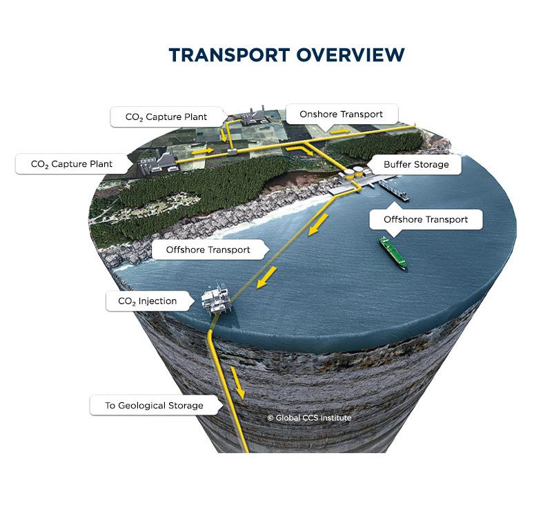
An FSIU – either a newbuild or converted existing offshore asset – receives liquefied CO2 from specialised carriers, stores and conditions it onboard, and ensures continuous injection into subsea wells for permanent storage in depleted oil and gas reservoirs or saline aquifers. Unlike fixed offshore platforms or long subsea pipelines from shore, floating facilities have the flexibility to be deployed incrementally and relocated as earlystage CCS markets continue to evolve.
Northern Lights: a proof point for scale
The Northern Lights project in the Norwegian North Sea illustrates how CCS value chains can mature when commercial alignment, government support and industrial demand converge. Equinor, Shell, and TotalEnergies have taken final investment decision on phase two of the project, which has been underpinned by substantial government support – the Norwegian government covered approximately 80% of the cost for Phase 1, while Phase 2 has received €131 million from the EU funding programme, Connecting Europe Facility (CEF).1, 2
Other projects are now approaching FID, including APOLLO CO2, which has been awarded €169.3 million in funding under the EU’s 5th Innovation Fund Large-Scale Projects Call.3 The project, a collaboration between the Greek natural gas system operator DESFA and ECOLOG, aims to create the first largescale CCS hub in Greece by 2030, with a first phase capturing 3 - 5 million t of CO2 from industries in the Attica region, with the possibility of scaling up to 10 million t. Meanwhile, EnEarth, a subsidiary of UK oil and gas group Energean, is developing the Prinos Carbon Storage Project, also backed by EU funding, while Malaysian energy giant Petronas was recently awarded the first Offshore Assessment Permit for CCS for the Duyong field, located offshore Peninsular Malaysia.4, 5
These developments underscore several lessons relevant to floating injection concepts: customer commitment is decisive, public-private partnerships reduce risk and catalyse investment, and scalable infrastructure unlocks further demand. Floating solutions may offer a complementary pathway, particularly where onshore infrastructure faces permitting constraints or where storage sites are remote.
Why offshore, and why floating?
Offshore storage offers several advantages over onshore alternatives. Regulatory and environmental constraints are often less complex; public acceptance risks are reduced; and mature hydrocarbon basins offer significant subsurface capacity and existing skills and knowhow to support the project. Floating injection facilities add another layer of flexibility, acting not only as injection hubs but also as processing and transfer platforms.
FSIUs can support regions where pipeline transport is not feasible or economical, enabling ship-based CCS networks to emerge. Their mobility allows operators to match infrastructure investment with market development, reducing upfront capital risk.
The impurities barrier: why standardisation matters
Despite its promise, offshore CCS – floating or otherwise –faces substantial challenges. Regulatory frameworks remain fragmented, long-term liability is not uniformly defined, and economic models are still evolving. Storage operators must identify and mitigate operational risks while assuring regulators and the public of safe, permanent containment. One of the most pressing technical barriers, however, is the issue of CO2 impurities.
Today’s liquid CO2 (LCO2) carrier fleet is largely built to customised specifications, which increases costs, limits fleet scalability and creates bottlenecks across the value chain. This customisation is driven by uncertainty over impurity compositions and their impacts on materials, safety, and operability.
Standardisation could be transformative. By defining acceptable impurity ‘envelopes’, designers and operators could move toward speculative newbuilding of CO2 carriers and associated floating infrastructure. Classification societies such as ABS are actively working with industry and academic partners – including Texas A&M University and Sintef, one of Europe’s largest independent research organisations –to close knowledge gaps around impurity behaviour and materials compatibility.6, 7 Solving this challenge could unlock significant pent-up demand for offshore storage solutions.
About ABS
As an independent and trusted third party, ABS is uniquely positioned to help convene stakeholders, educate the market and foster alignment across the offshore CCS ecosystem. While not a solutions provider, ABS plays a critical role in nurturing the conversations and collaborations from which safe, commercially viable and scalable solutions can emerge. Floating offshore CO2 injection facilities will not solve climate change alone but as part of an integrated carbon value chain, they may prove to be one of the most adaptable tools available. The conversation is moving quickly. The question is whether the industry can move together.
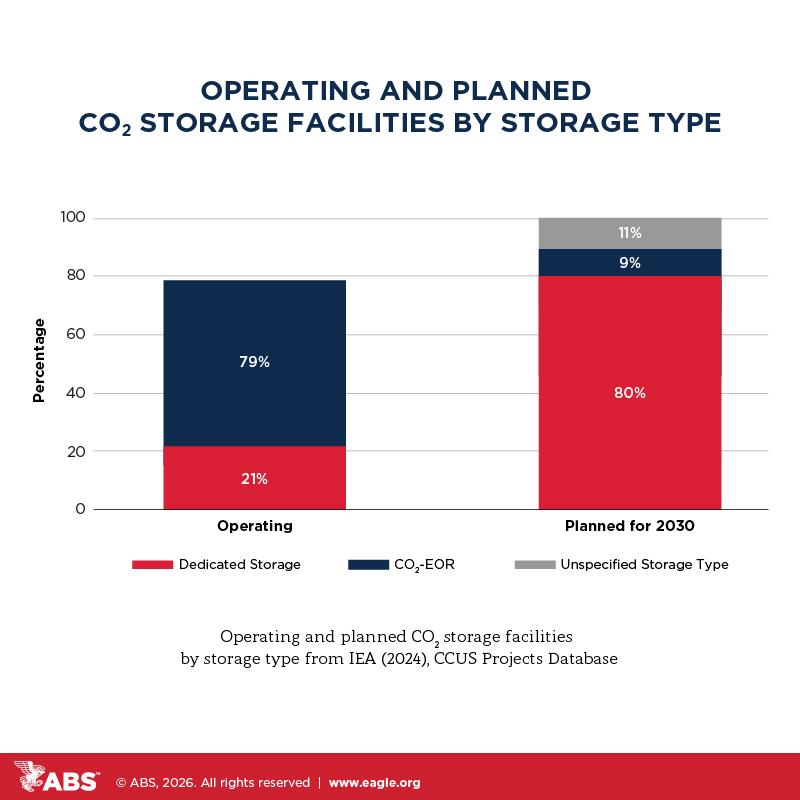
Figure 1. Operating and planned facilities (image credit: ABS).
Figure 2. Transport overview figure (image credit: Global CCS Institute, 2025).
Neil Gordon, CEO, Global Underwater Hub (GUH), outlines how oil and gas still matter to the underwater supply chain, and that it will still matter for decades to come.
ot even a week into 2026 and oil and gas was catapulted back to the top of the global news agenda. Then weeks later, it hit the headlines again as conflict erupted in the Middle East.
Political upheaval in Venezuela, home to the world’s largest proven oil reserves, meant the eyes of much of the industry were fixed squarely on South America hotly awaiting the next move. That story gained a UK angle when a tanker, accused of breaking sanctions and carrying oil for
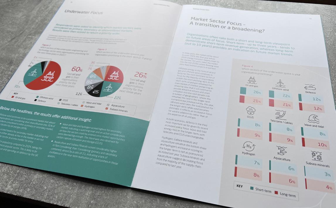
Figure 1. GUH’s Business Survey 2025 exposed a strong consensus amongst the supply chain that international markets currently offer greater opportunity than the UK.
Venezuela, Russia, and Iran, was seized by US authorities and moored in the Moray Firth for weeks.
As plans for its return across the Atlantic were revealed, the US and Israel launched attacks on Iran that set in motion a conflict which would impact the wider Middle East and send the oil price soaring globally.
What these dramatically different situations demonstrate, is that for all the worthy progress that has been made in scaling up the renewables and low carbon sectors, oil and gas still dominates the global energy industry and has significant repercussions on the world economy.
As we saw four years ago with the war in Ukraine and has been evidenced again this year, geopolitical tensions lead to fears around nations’ energy security, such is the global nature of the oil and gas industry. For countries, including the UK, that are adopting policies that heavily drive investment into renewable energy and taper off hydrocarbon production to advance the energy transition at pace, the wide-ranging impact of global hostilities should not be overlooked.
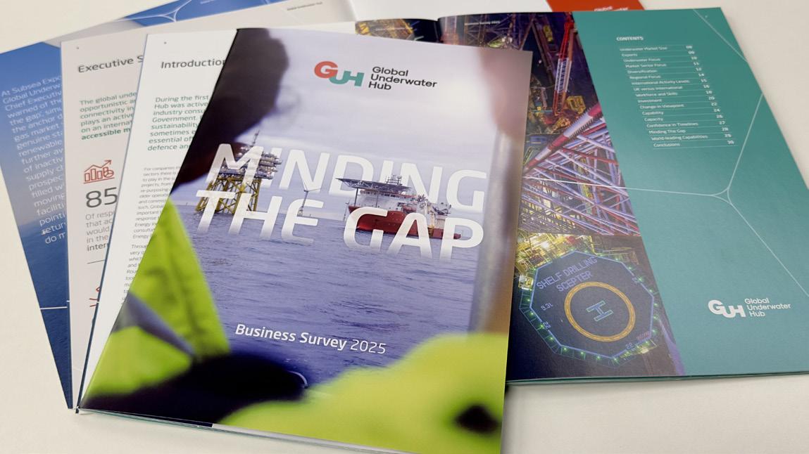
Global Underwater Hub’s (GUH) Business Survey 2025 underscored a central issue facing the sector, a growing misalignment between the decline of traditional oil and gas activity in the North Sea, and the slower-than-anticipated ramp-up of renewable energy projects.
This misalignment risks creating a gap in utilisation for the underwater supply chain, a gap that hydrocarbon activity, especially in international markets, is currently helping to fill.
Oil and gas as the anchor market
Change is part and parcel of any industry, but for those of us who have spent our careers working in energy, it is one of just a few constants. The long-term trajectory toward lower-carbon energy is clear, yet the near- and medium-term realities of project delivery, investment cycles and workforce retention present significant challenges.
Despite sustained policy focus on renewable energy, oil and gas remains the dominant market for the UK underwater supply chain in the short-term. Survey results show that 60% of respondents consider hydrocarbons their primary market over the next three years, with 95% either active in or prioritising the sector. These figures aren’t a rejection of the energy transition, rather they highlight the continued availability of defined, executable projects that require subsea engineering, installation, inspection and life-of-field services.
Oil and gas projects continue to progress from concept to execution with greater certainty than many emerging energy developments. For supply chain companies managing high-value assets such as construction vessels, ROV fleets, fabrication facilities and specialist engineering teams, this certainty is essential. Without a dependable pipeline of work, companies face the prospect of idle capacity, deferred investment and the erosion of hard-won technical expertise. In this context, oil and gas plays a stabilising role. It provides the utilisation necessary to maintain industrial capability while newer markets scale up. Importantly, it also underpins the financial resilience required to invest in innovation, diversification and workforce development.
The Energy Profits Levy introduced by the UK Government has had a significant detrimental effect on the oil and gas industry in the UK. Continued campaigning by industry representatives and engagement with the Chancellor of the Exchequer and Treasury officials has in recent weeks hinted at policy change, which if delivered could unlock investment and domestic market opportunity for the supply chain.
International markets and project cadence
While it’s a trend that many had suspected for some time, GUH’s latest report exposed in no uncertain terms the strong consensus amongst the supply chain that international markets currently offer greater opportunity than the UK. In the short-term, 85% of respondents expect international activity levels to increase, rising to 91% over the longer term. By comparison, confidence in domestic project flow remains more subdued.
International oil and gas regions – including South America, West Africa, and parts of Asia – continue to sanction new developments and invest in brownfield upgrades. These projects are often supported by clearer regulatory frameworks, more predictable approval processes and a stronger sense of project cadence. For the underwater supply chain, this translates into higher confidence that announced projects will proceed and that timelines will be broadly maintained.
As a result, UK companies are increasingly looking outward to secure utilisation. While this export success demonstrates the global competitiveness of the UK underwater sector, it also raises strategic questions. If international projects consistently move faster and offer
Figure 2. GUH’s Business Survey 2025 underscores a growing misalignment between the decline of traditional oil and gas activity in the North Sea and the slower-than-anticipated ramp-up of renewable energy projects.
Figure 3. GUH’s report analyses the top priority sectors in the underwater space among its members.
greater certainty, there is a risk that assets, personnel and even operational bases migrate permanently overseas.
Brownfield activity and life-extension
Much of today’s oil and gas work is concentrated in mature fields rather than new greenfield developments. Brownfield activity, including inspection, maintenance, repair, integrity management and life-extension, remains a major source of demand for underwater services. These activities are technically complex and draw directly on the UK supply chain’s core strengths.
Decades of operating in harsh offshore environments have given UK companies world-leading expertise in subsea inspection, monitoring technologies, ROV and AUV operations, and data-driven asset management. This capability is sustaining oil and gas production while, in tandem, reducing emissions by improving efficiency and avoiding unnecessary interventions.
Crucially, these same skills are transferable, and the experience gained through managing ageing hydrocarbon infrastructure is directly applicable to adjacent markets – such as carbon capture, utilisation and storage (CCUS) –where long-term integrity and monitoring of subsea assets will be critical. Supporting diversification into these adjacent markets requires alignment between policy, regulation and funding mechanisms so that companies can justify adapting existing technologies rather than developing entirely new ones from scratch.
Investment and confidence
Investment remains a cornerstone of competitiveness in underwater markets. The survey shows that 93% of respondents expect additional investment to be required in the short-term, increasing to 96% over the longer term. While offshore wind continues to attract strong investor interest, oil and gas has seen a notable improvement in perceived ease of accessing finance compared with previous years.
This shift reflects the continued availability of bankable projects and clearer revenue models in oil and gas. Where investment confidence is stronger, companies are better able to commit capital to vessels, tooling, digital systems and workforce expansion. Conversely, where project timelines are uncertain, even strategically important markets can struggle to unlock investment.
The Iran War and subsequent counter attacks have demonstrated how susceptible energy production in multiple countries is to disruption. Market confidence and investment in the Middle East have been impacted, affecting supply chains. The full toll of the conflict on the oil and gas market will likely take a long time to be calculated.
These political tensions show that the need for consistency in domestic policy frameworks is therefore critical and more pronounced than ever. Long-term, stable signals – across oil and gas, renewables and adjacent sectors – allow companies to plan strategically rather than react tactically. Frequent or material changes in policy direction increase risk and can delay or deter investment decisions that take years to realise returns.
Workforce and skills retention
The ability to deliver future underwater projects depends on people as much as it does investment and policy, with survey
respondents anticipating significant growth in workforce requirements, particularly for technical roles. The majority (85%) expect technical headcount to increase for future markets, with 15% anticipating growth of more than 50%.
Attracting, training and retaining this workforce is increasingly challenging as competition for skilled engineers, technicians and offshore personnel intensifies, not only within the energy sector but across the wider economy. Oil and gas projects continue to provide a vital training ground, offering early-career professionals exposure to complex subsea systems, offshore operations and large-scale project delivery.
Maintaining this skills pipeline requires continuity of work. Periods of inactivity or uncertainty risk driving talent away from the sector altogether. Targeted collaboration between industry, government and academia is therefore essential to ensure that training pathways align with future demand and that the underwater industry remains an attractive long-term career choice.
Managing the transition, not increasing the gap
Our research makes clear that the UK underwater supply chain is both capable and ready, with 84% of respondents believing they currently have the capability to compete effectively in their chosen markets, rising to 86% when considering future markets. Capacity, too, is available, with 81% confident they can meet current objectives.
But with just 39% of projects expected to maintain planned timelines, limiting confidence and complicating resource planning, the challenge is cadence, not capability. If oil and gas activity declines faster than renewable and emerging markets scale up, the resulting gap risks undermining the very supply chain required to deliver the energy transition.
A managed transition therefore requires balance and oil and gas activity, particularly where it focuses on efficiency, emissions reduction and responsible decommissioning, should be seen as an enabler rather than an obstacle. At the same time, accelerating the delivery of domestic renewable and CCUS projects through clearer timelines, streamlined processes, and consistent policy support will be essential to absorbing capacity as the market evolves.
Facing up to the realities
We must build a future, not built on ideology or nostalgia, but rather practicality. Oil and gas continues to set the pace of the global offshore energy system, not because the transition has failed, but because it is a transition. The UK underwater supply chain understands this better than most. It has diversified, invested, innovated, and prepared for what comes next, yet it cannot operate in a vacuum of stalled projects and uncertain timelines.
What our latest Business Survey makes unambiguously clear is that capability is not the constraint. Nor is willingness. The constraint is cadence. Where projects move, investment follows; where investment flows, skills remain; and where skills remain, the transition has a fighting chance of succeeding. At present, too many of those conditions are being met overseas rather than at home.
Patrick Hayes, Tracerco, highlights how evolving operator priorities are reshaping measurement strategies.
cross the upstream sector, operator priorities are shifting. In many regions, the industry has moved away from long cycle megaprojects and toward shorter cycle developments that demand faster returns and more disciplined capital allocation. This change has placed greater emphasis on operational efficiency, production optimisation, and rapid decision making across the life of an asset.
As a result, production monitoring technologies are evolving in both purpose and importance. Historically, monitoring solutions were often deployed to troubleshoot individual well issues once production problems emerged. Today, operators increasingly require measurement technologies that can confirm well performance, validate reservoir models, and support development programme efficiency from the earliest stages of production.
In this environment, the ability to obtain reliable subsurface flow insight quickly and without intervention is
becoming increasingly valuable. Technologies such as tracers are enabling operators to better understand how wells perform in complex reservoirs, identify production challenges earlier, and make more informed decisions to maximise hydrocarbon recovery.
Capital discipline and changing development strategies
Recent years have seen upstream operators adopt more cautious investment strategies in response to market volatility and shifting energy priorities. Large scale developments with long payback periods are increasingly supplemented or replaced by projects that deliver faster returns and lower risk.
This shift has implications for production monitoring. When development cycles shorten, operators require measurement solutions that can deliver reliable performance insight without introducing operational complexity or delays. Monitoring technologies must support rapid interpretation and provide actionable information that can be integrated into production planning and reservoir management workflows.
In unconventional developments and mature offshore fields alike, the ability to confirm production contribution and fluid movement within the reservoir has become central to achieving these objectives. Operators need to understand which sections of a well are contributing hydrocarbons, how injection programmes are influencing sweep efficiency, and where unwanted fluids, such as water, are entering the production stream.
Production monitoring technologies that can provide this insight help operators reduce uncertainty, optimise completion strategies, and improve recovery while maintaining operational efficiency.
The growing importance of measurement insight
Reservoir complexity is increasing across many producing regions. Multistage horizontal wells, advanced completion designs, and large waterflood programmes have significantly improved production potential but have also introduced new challenges in understanding subsurface behaviour.
In such environments, traditional monitoring approaches often struggle to provide the level of detail required to guide optimisation decisions. Surface measurements and conventional production logging may offer partial insight but can be limited by operational constraints or the need for intrusive well intervention.
Operators therefore increasingly seek measurement solutions that can provide detailed production information while maintaining operational simplicity. Non-intrusive technologies are particularly valuable because they allow monitoring programmes to run alongside normal production operations without requiring well intervention or disruption.
Tracer technologies represent one such approach. By introducing identifiable markers into specific locations within the reservoir or completion, tracers allow engineers to track the movement of fluids through the production system and identify where production contributions originate.
This capability provides operators with valuable information about well performance, reservoir communication, and the effectiveness of injection programmes.
Tracer technologies supporting production optimisation
Tracer technologies are used across a range of upstream monitoring applications. These include inflow profiling, interwell communication analysis, and completion integrity verification. Each of these applications provides operators with different forms of insight into reservoir behaviour and well performance.
During inflow monitoring, tracers are deployed within specific zones or stages of a well completion. By analysing produced fluids for the presence of these tracers, engineers can determine which sections of the well are contributing oil, gas, or water to the production stream. This information helps operators identify underperforming zones and evaluate the effectiveness of completion strategies.
Interwell tracer studies provide a different form of insight. By introducing tracers into injection wells and monitoring their appearance in surrounding producers, operators can determine the direction and speed of fluid movement within the reservoir. This helps assess sweep efficiency, identify preferential flow paths, and improve the design of waterflood or enhanced recovery programmes.
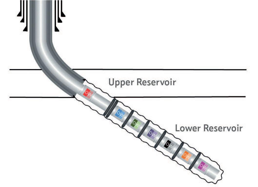
Figure 1. Production well tracer design showing placement of inflow tracers along the lower reservoir completion and completion integrity tracer in the isolated upper reservoir.
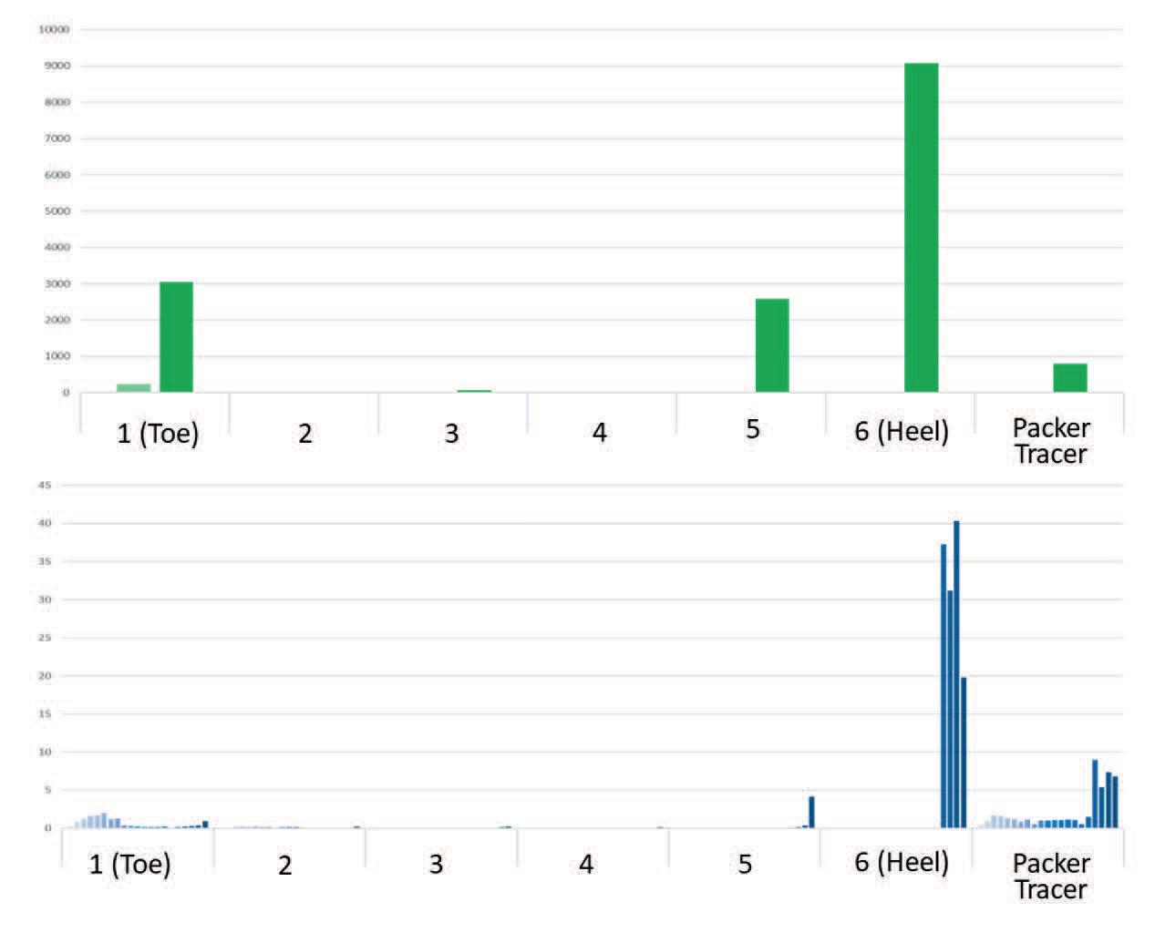
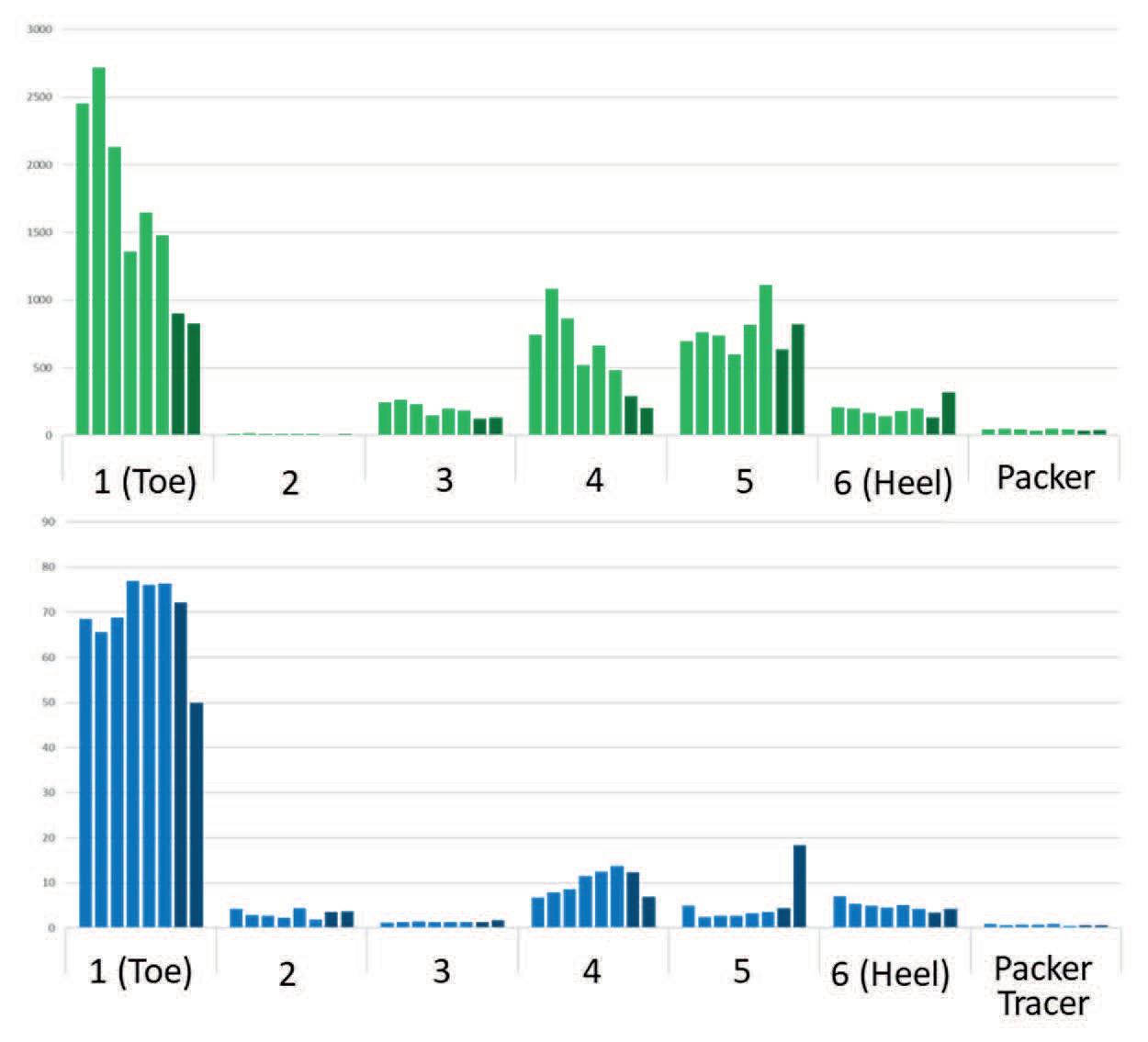
Figure 2. Oil and water tracer concentration during well clean up, showing dominant water contribution from the heel section of the well.
Completion integrity tracers provide yet another layer of understanding. These tracers can be used to confirm the integrity of packers, barriers, and other completion components by identifying whether fluids are bypassing intended flow paths.
Together, these monitoring approaches provide operators with a clearer understanding of subsurface flow behaviour. This information supports more effective reservoir management and enables targeted intervention strategies where necessary.
Case study: identifying the source of unwanted water production
Tracer technology can be particularly valuable in mature fields where water production begins to impact oil output and operating costs.
In one mature offshore oilfield development in the North Sea, an operator was experiencing significant water production from a newly drilled infill well. Excess water production can reduce oil processing capacity and increase treatment costs, making it critical to identify the source of the water and determine appropriate mitigation strategies.
Water entering the production stream may originate from several sources. These include water coming from the reservoir, high permeability channels, injection breakthrough from nearby wells, or potential well integrity issues within the completion.
To determine the source of the produced water, Tracerco’s tracer technology was deployed in both the new production well and several nearby injection wells. The monitoring programme used a combination of solid inflow tracers and completion integrity tracers placed at multiple positions along the wellbore. These tracers were installed in separate compartments within the lower reservoir completion, with an additional tracer positioned in an isolated upper reservoir section (Figure 1).
At the same time, liquid waterflood tracers were injected into several nearby water injection wells. These tracers allowed engineers to monitor potential communication between the injection wells and surrounding producers.
Over time, samples from the production well and neighbouring wells were collected and analysed to detect the presence of these tracers. The resulting data allowed engineers to build a detailed picture of fluid movement within the reservoir and identify the origin of the produced water.
During the clean-up phase of the well, water cut was observed to increase rapidly. Initial water production reached approximately 88% before rising to more than 90% as oil production declined.
Tracer analysis during this stage revealed that most of the produced water originated from the heel section of the well, with additional water contribution detected from the toe section. The tracer positioned in the upper reservoir section was also detected during early production due to temporary communication through the annulus before the swell packers had fully sealed (Figure 2).
As production stabilised and the swell packers fully sealed the annular section between the upper and lower reservoirs, further tracer analysis was conducted under steady state flow conditions.
These results confirmed that water inflow was continuing from both the toe and heel sections of the producing interval, while the packers were successfully preventing fluid communication from the upper reservoir through the annulus.
The detailed inflow profile provided by the tracer analysis allowed engineers to confirm the precise locations of water entry along the wellbore (Figure 3).
Following a brief shut in period, the well was restarted and additional tracer measurements were collected. The restart analysis confirmed that water influx from both the toe and heel
sections continued after the shut in event, while the packer system maintained effective isolation of the upper reservoir.
These results provided further confirmation of the water entry locations and reinforced the understanding of fluid flow behaviour within the well.
In parallel with the inflow tracer study, liquid waterflood tracers injected into surrounding injection wells were monitored in nearby producers. This allowed engineers to assess interwell communication and evaluate the effectiveness of the waterflood programme.
By combining the results of the inflow and interwell tracer analysis, the operator gained a comprehensive understanding of fluid movement within the field. The study helped identify the origin of the produced water and provided critical information to guide reservoir management and production optimisation strategies.
Case study: optimising production contribution in a deepwater field
Tracer monitoring can also play an important role in helping operators understand how different zones contribute to production in complex offshore developments.
In one deepwater oilfield development, an operator sought to better understand production contribution across multiple zones within a producing well. While the well had been successfully
completed and brought online, there was uncertainty regarding the relative contribution of each producing interval and whether the completion design was delivering optimal performance.
To address this challenge, Tracerco deployed a series of chemical inflow tracers within the well completion. These tracers were installed at selected production intervals, allowing engineers to track fluid contributions from each zone during normal production operations (Figure 4).
By analysing produced fluids for the presence of the tracers, engineers were able to identify the proportion of oil production originating from each section of the well. The results revealed significant variation in production contribution between the monitored zones.
This insight enabled the operator to refine its understanding of reservoir behaviour and confirm which sections of the well were performing most effectively. The tracer data also provided valuable validation for reservoir models and helped guide future completion and field development strategies.
For operators managing complex deepwater assets, this type of production monitoring can provide critical information that supports optimisation decisions without requiring intrusive logging operations or production interruptions.
The future of production monitoring
As upstream development strategies continue to evolve, production monitoring will play an increasingly strategic role in reservoir management and production optimisation.
Operators are seeking measurement solutions that provide reliable performance insight while maintaining operational simplicity and cost efficiency. Technologies that deliver actionable subsurface information without requiring complex intervention will therefore become increasingly valuable.
Tracer technologies offer a powerful tool for achieving this objective. By providing detailed information about inflow behaviour, interwell communication and completion integrity, tracer studies help operators better understand reservoir performance and make more informed decisions throughout the life of a field.
Because the monitoring process relies on analysing produced fluids rather than deploying intrusive logging tools, tracer studies can often be conducted without interrupting normal production operations.
In a sector where efficient production and rapid decision making are becoming ever more important, advanced monitoring technologies are helping to bridge the gap between subsurface uncertainty and operational confidence.
About the author
Patrick Hayes is Tracerco’s Business Development Manager for North America. Having joined Tracerco in 2004, Patrick has proven his expertise in chemical tracer technology by managing global, multi discipline projects with a focus on improving operator efficiencies and increasing customer’s return on capital investments from upstream through to downstream industries.
While working in the North Sea, Europe, Middle East, and parts of West Africa, Patrick’s innovative approach to applying novel measurement technologies has helped customers gain additional insight into the different aspects of the hydrocarbon production cycle from subsurface to midstream through to downstream refining.
Patrick is now focused on working with operators in North America to help them to gain production efficiencies through the better understanding of the relationships between reservoir characteristics, completions, and production.
Figure 3. Oil and water tracer profiles in steady state production conditions, confirming water entry points along the wellbore.
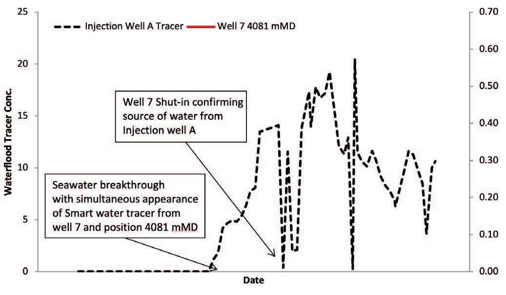
Figure 4. Tracer response confirming seawater breakthrough from an injection well into a nearby producer in a deepwater field.
www.worldpipelines.com
Dinesh Krishna Mohan, Digital/Asset Performance Management (APM) and Technology Project Manager for Schlumberger Technology Corp. (SLB), is interviewed by Ellen F. Warren, and shares how he transforms complex sensor data into operational insights, drives global process improvements, and develops scalable frameworks that extend asset life and performance.

inesh Krishna Mohan is a digital project manager and asset performance expert with nearly two decades of industry experience, including more than fourteen years in the global oil and gas sector. As a Digital/Asset Performance Management (APM) and Technology Project Manager, he draws on an extensive background in engineering, equipment testing, refurbishment, and industrial analytics to advance equipment health monitoring and condition-based maintenance, grounding technical insight in operational data. In his current role with Schlumberger Technology Corp. (SLB), one of the world’s leading oilfield services and technology companies, he applies prognostics and health management (PHM) to help organisations move from reactive maintenance toward more predictive, reliable decision-making.
Across senior technical and leadership roles, Dinesh has developed scalable analytical frameworks that translate highfrequency operational data into insights engineers can trust and act on. He has led complex digital initiatives involving large industrial asset bases, managed multi-million-dollar programmes, and delivered measurable improvements in reliability and uptime.
Dinesh holds a Bachelor of Engineering in Mechanical Engineering from Anna University in India and a Master of Science in Mechanics and Processing of Materials from Nanyang Technological University in Singapore. In this interview, he discusses the practical realities of implementing PHM at scale, the importance of interpretability and engineering context in analytics, and his perspective on advancing data-driven reliability in complex industrial systems.
Ellen Warren (EW): Can you walk us through how your early work in reliability and asset management shaped the way you now approach data-driven prognostics and health management (PHM) for complex industrial systems?
Dinesh Krishna Mohan (DM): Early in my career, I was deeply involved in root-cause analysis of equipment failures globally. That work required correlating operational sensor data with physical failure modes and, in many cases, redesigning components to eliminate frequent failures. I later carried this expertise into factory acceptance testing, where I analysed multisensor data to understand why systems failed performance criteria. These experiences gave me a strong intuition for how signals across subsystems interact. Today, that foundation directly informs how I frame PHM hypotheses, select meaningful parameters, and design models that are grounded in real failure behaviour rather than purely statistical patterns.
EW: Asset Performance Management (APM) has evolved rapidly over the past decade. From your vantage point, what fundamental shifts have you seen in how organisations think about reliability, maintenance, and decision-making and where do you believe many companies still misunderstand the true value of APM?
DM: Over the past decade, Asset Performance Management has moved from being a maintenance-owned, largely reactive activity to a more integrated, lifecycle driven approach. Earlier, reliability improvements mostly came from learning after failures and updating maintenance practices based on what went wrong in the field. This later shifted toward engineering-led maintenance, where scheduled maintenance plans were defined during product design and commercial launch, typically based on operating hours. While this improved consistency, it often resulted in over or under maintenance, and in some cases, critical degradation mechanisms were not adequately addressed.
The major shift came with the adoption of PHM and data analytics, which enabled maintenance decisions to be based on actual equipment behaviour rather than assumptions. Organisations now see that analysing historical and operational data allows degradation to be detected earlier and maintenance to be performed more effectively. That said, many still view condition-based maintenance mainly to avoid failures. Its larger value is in keeping assets operating within optimal ranges, slowing long-term degradation, extending usable life, and ultimately improving capital efficiency.
EW: Much of your work applies PHM and analytics to oilfield and energy equipment operating in harsh, remote, and high-variability environments. How do you design analytics strategies that remain reliable when data is incomplete, noisy, or delayed, yet still support confident maintenance decisions in the field?
DM: In oilfield environments, data being noisy or delayed is normal, so the analytics are designed with that in mind. For noisy data, we rely on domain knowledge to design the filters and eliminate the noise during the ingestion of data. We know what the process limit is for each sensor and so filtering rules are applied early to remove obvious noise. In addition, noise also comes from operational transitions, and so tagging the data to know what stage of the operation the data belong to is critical. By identifying the operating state, we can focus the analysis on steady and meaningful data and avoid drawing conclusions from transient data. With delayed data, since most of what we monitor is degradation based, the trends evolve over time, and so giving enough margin to act before conditions deteriorate to a failure point should take a couple of days of delay. With regards to incomplete data, data is often transmitted in chunks, which means we may not see the full picture immediately. The same degradation trend approach applies. Partial data is usually enough to understand the direction of change. As more data arrives, the picture fills in and confirms the actual condition.
EW: You recently published work outlining a scalable PHM framework that treats prognostics as a structured pipeline – moving from raw sensor data through layered processing, modelling, and decision logic rather than as isolated analytics. What motivated you to formalise PHM in this way, and how does this layered approach improve the reliability and actionability of condition-based decisions in complex industrial environments?
DM: This approach came from real field experience. We saw that even when PHM models raised alarms, teams still had to manually check whether the alert was real or just noise caused by sensor spikes, operating transitions, or equipment being powered on but not actually working. That extra investigation slowed teams down and reduced trust in the PHM outputs. It became clear that the problem wasn’t just the model, but everything around it.
We addressed this by structuring PHM as a layered pipeline, first cleaning the data and removing noise, then tagging operational states, and only then applying models and decision logic. This reduced false alarms and made results more consistent. As the solution was rolled out to multiple regions, the same pipeline allowed us to scale easily and incorporate feedback from different operating conditions, improving the models globally and making condition-based decisions more reliable and actionable.
EW: Scaling condition-based maintenance in oilfield operations often means integrating CBM into environments with strict uptime requirements, safety considerations, and distributed assets. From your experience, what separates organisations that successfully operationalise CBM in these settings from those that struggle to move beyond pilots?
DM: In my experience, organisations that successfully scale condition-based maintenance usually get three things right. First, there is a clear vision from maintenance and operations
leadership to move beyond reactive or purely scheduled maintenance and deliberately adopt PHM as part of how work gets done. When that direction is set top-down and translated into clear expectations, CBM stops being a pilot and becomes part of the maintenance workflow.
Second, the solution is designed to fit operational realities. That means thinking through how data is collected, where analytics should run, and who needs to act on the results. In settings where data can be transmitted reliably, remote monitoring allows reliability teams to review insights and escalate only genuine issues to the field. Where data latency is a challenge, edge based solutions that operators or maintenance teams can use directly are more effective. In both cases, involving end users during development is critical so solutions that address real problems get adopted, while overly complex analytics often do not.
Finally, for CBM to scale, it must be embedded into daily workflows and, over time, into core business systems. Once the approach matures, insights should flow directly into maintenance planning, work order creation, and asset management processes. When CBM becomes part of how decisions are made rather than an extra dashboard to check it is far more likely to be sustained and deliver long-term value.
EW: A recurring theme in your work is translating technical insights into decision support for operators, engineers, and leadership. How do you ensure that advanced analytics actually influence decisions on the ground, rather than remaining confined to dashboards or reports?
DM: Most dashboards fail to influence decisions because the people expected to use them don’t trust the results or don’t see them as relevant to their day-to-day work. To avoid that, operators and maintenance teams are involved early in the development process. Start by understanding the problems they actually face in the field and use their input to shape what the models look for and how results are presented. That involvement builds ownership, so the solution is seen as something built with them, not imposed on them.
Also keep the feedback loop active. Through regular touchpoints, we review how the outputs are being used, clarify how to interpret them, and collect feedback to refine the models. Over time, confidence builds as the analytics flag issues that would have been missed by routine inspections or scheduled maintenance. Once teams see that the insights consistently support better decision, the dashboards stop being reports and start becoming part of the normal maintenance workflow.
EW: Reliability engineering has traditionally relied on physics-based models and domain expertise, while modern APM increasingly incorporates data-driven methods. How do you balance these approaches, and where do you see the greatest opportunities for integration?
DM: Physics-based models work well when all the right sensors are available to provide data for all the parameters the model depends on. In many legacy assets, those sensors were never designed in, so building a full physics-based model is not always practical. In those cases, we rely on domain knowledge of how the system operates, combined with historical data, failure records, and maintenance history, to understand typical behaviour and identify degradation patterns that can be modelled from data.
If sufficient sensors are available, then physics-based models are very effective and we do use them. However, another limitation is that physics-based models typically assume nominal or near-new conditions and may not fully account for changes caused by different types of wear, clearance and wobbling etc. Data-driven models, trained in historical operating behaviour, naturally reflect how equipment degrades in the field. The biggest opportunity is in combining both approaches, using physics to guide model structure and data-driven methods to adapt to realworld behaviour resulting in more precise and practical PHM solutions.
EW: Throughout your career, you’ve worked across engineering, analytics, and business strategy. How has this cross-disciplinary role influenced your leadership approach when working with diverse technical and operational teams?
DM: Working across these diverse disciplines has helped me look at problems from multiple angles. When I work with different technical and operational teams, I focus on keeping things simple and making sure the solution actually helps the business and the people using it. That mindset helps teams stay aligned on what really matters instead of getting stuck only on technical details.
I’ve seen that when solutions are built only from a theoretical or very conservative engineering point of view, they often lead to replacing parts too frequently and driving up material and maintenance costs. Bringing business context into the discussion helps strike a better balance between theory and what works in the field. As a leader, this helps teams design solutions that are practical, cost-effective, and easier to adopt in real operations.
EW: In your view, what is the next major frontier for asset performance management and PHM – and how should organizations and engineers prepare to meet the reliability challenges of increasingly autonomous and data-intensive industrial systems?
DM: The next major frontier for asset management is making systems more autonomous without compromising reliability. From developing PHM models, one of the clear gaps we have identified is not having enough or correct sensor types. Many false alarms or missed detections happen because of this. Using insights from PHM deployments to guide where additional or better sensors are needed is critical to improving accuracy and building trust in more autonomous systems.
Another important thing is better decision support along with the analytics. Tools like GenAI and large language models can help engineers and operators quickly access relevant knowledge from manuals, historical failure reports, and past maintenance actions when troubleshooting issues. In parallel, time-series foundation models offer strong potential in APM by learning patterns across large volumes of operational data and adapting to different assets and operating conditions. Together, these advances can help organizations move beyond detecting issues to guiding decisions in data intensive equipment that operates in harsh and remote environments.
Note
The views expressed by Dinesh Krishna Mohan in this interview are entirely his own and do not represent Schlumberger Technology Corp. (SLB).
COVER STORY
Jim Crenshaw, Global Technical Advisor, and Sanjay Vitthal, Global Technical Advisor, Superior Energy Services EcoReach, discuss evolving production optimisation through microproppant technology.
perators are under increasing pressure to improve well productivity while reducing costs and minimising environmental impact. This has increased interest in completion approaches designed to improve reservoir response while lowering operational intensity. EcoReach, a broad sieve non-synthetic microproppant technology developed by Superior Energy Services, is designed
to improve stimulated rock volume, extend production performance and simplify execution across a range of reservoir conditions.
The technology addresses long-standing limitations in conventional completions, particularly uneven fracture coverage and rapid production decline. Traditional proppant systems often fail to effectively access complex fracture networks, limiting reservoir response and long-term recovery while increasing operational complexity. By enabling broader distribution within the fracture system and reducing reliance on complex fluid chemistries, EcoReach
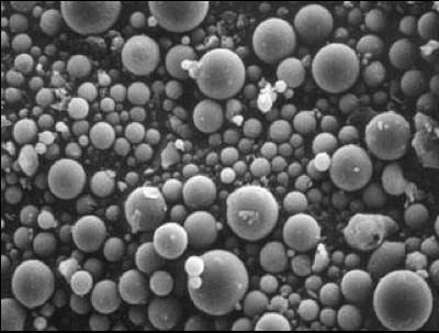
provides an approach that supports reservoir connectivity, operational efficiency and reduced environmental impact (Figure 1, showing broad sieve proppant under microscope).
EcoReach focuses on improving reservoir connectivity rather than relying solely on fracture size or intensity. This approach is intended to increase effective contact with hydrocarbons resulting in more stable production over time.
The result is a shift in how completion performance is evaluated, placing greater emphasis on sustained connectivity and overall recovery rather than initial production rates alone. This change reflects a broader industry trend toward optimising total recovery and longterm asset performance rather than focusing exclusively on early production metrics.
Technology development and material science
EcoReach BSP, developed by Superior in collaboration with the University of Kentucky, is a natural byproduct of coal combustion (Figure 1) with unique minerology and rheologic characteristics. Rangeing in size from 150 micron to less than 1 micron, the proppant has high sphericity, crush strength over 15k psi, and specific gravity significantly lower than sand. These properties allow greater connected frack area geometry, penetration and opening of secondary fracture networks, and enhancing production longevity under high stress/depletion. Our work has progressed through laboratory testing, simulation modelling and field validation over the last eight years. Early research focused on understanding how small, lightweight particles behave under reservoir conditions and how their physical characteristics influence transport and placement within fracture networks.
Laboratory and simulation work indicated that the spherical microproppant particles, which are significantly smaller than conventional sand, remain suspended longer in fluid systems and are capable of penetrating deeper into complex fracture geometries. Conventional proppants tend to settle quickly and form localised accumulations, while the EcoReach particles distribute more uniformly throughout the fracture network. This behaviour supports broader fracture coverage and improved cluster efficiency, particularly in formations with complex natural fracture systems.
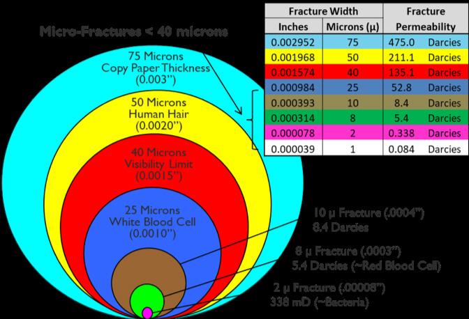
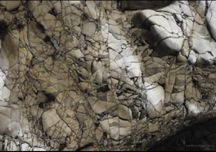
The difference in transport behaviour can be described in terms of distribution patterns. Conventional sand often forms concentrated deposits within dominant fractures, while broad sieved proppants disperse more evenly across both primary and secondary fracture pathways. This allows creation of a more extensive fracture networks that may not be achievable with larger proppant. (Figure 2 demonstrates the effective permeability obtainable from secondary micro fracture networks). As a result, a greater portion of the reservoir (Stimulated Rock Volume) can be connected for improved production. (Figure 3 shows the complex secondary fracture network EcoReach is able to penetrate and create stimulated rock volume).
This distinction contributes to a shift in how fracture effectiveness is evaluated. While traditional approaches often prioritise conductivity within individual fractures, EcoReach emphasises connectivity across the broader fracture network. Connectivity reflects how effectively different fractures are linked and how accessible they are to fluid flow. Increasing connectivity expands the number of effective flow paths, which can enhance overall production performance even if individual fracture conductivity remains unchanged.
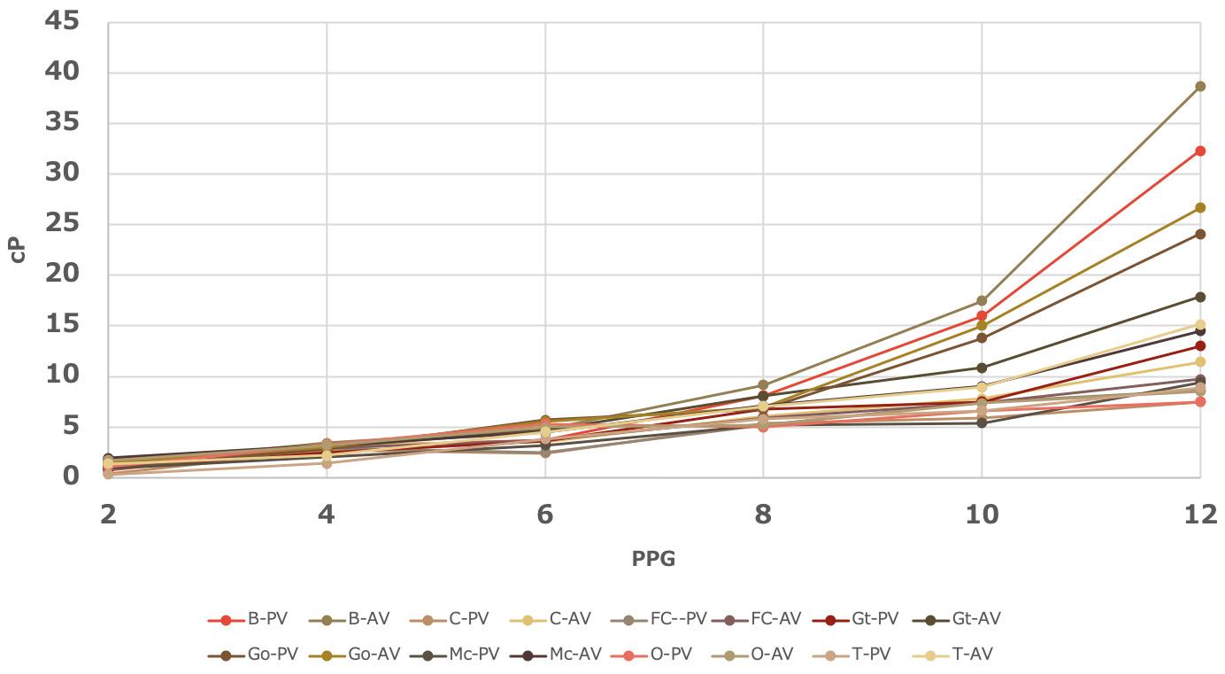
Laboratory testing has quantified several key performance characteristics of the material known as EcoReach. It exhibits a crush strength exceeding 15 000 psi compared to conventional sand, which has a crush strength ranging between 8000 - 12 000 psi. Flow behaviour testing shows that EcoReach slurry functions as a homogenous slurry
Figure 1. Zero polymer usage means clean proppant pack.
Figure 3. Ability to penetrate and prop microfractures.
Figure 2. Shows secondary fracture conductivity contributions from propped micro-fracture networks.
with Newtonian rheology even at proppant loadings of up to 10 lb/ gal. The slurry yield remains low, often near zero, indicating that minimal energy is required to initiate flow or penetrate small fractures (Figure 7).
Early field applications focused on existing wells with marginal production, providing a controlled environment for evaluating performance. These deployments demonstrated sustained production response and helped validate laboratory findings under operating conditions. By targeting wells with established production histories, operators were able to observe changes in performance following treatment with reduced operational risk.
Over time, applications expanded into more complex environments, including multistage horizontal wells and international projects. This progression reflects an evolution from targeted remediation in legacy wells to broader application across more advanced completion designs. The transition also highlights increasing confidence in the technology’s ability to perform under a wider range of reservoir conditions.
Field applications and global deployment
EcoReach has been applied across both new fracture treatments and re-fracturing operations, with configurations that include broad sieved non-synthetic microproppant-only systems as well as combined applications with conventional sand, depending on well design and reservoir conditions. This flexibility enables the technology to be adapted across a wide range of well types and operational objectives.
Since its acquisition by Superior, EcoReach has gained increased visibility and has been deployed across multiple basins and international markets. Initial applications in onshore environments have expanded to include multiple basins in the US and Middle East.
In a recent Middle East application, a well which previously delivered limited results from acid fracturing was recompleted using the EcoReach technology. The production increased from zero bpd of oil to over 200 bpd of oil.
In the Permian Basin, EcoReach was used to re-stimulate a horizontal well in the Wolfcamp formation that initially produced only gas due to its position above the intended oil zone. The well was isolated using a cast iron bridge plug, leaving a targeted section accessible for treatment and enabling a focused re-stimulation strategy.
Around 600 000 lbs of EcoReach were pumped through existing production tubing at low rates. Weighted fluid slugs were incorporated into the treatment to influence fracture growth direction and promote downward propagation toward the oil-bearing interval. This innovative approach was designed to improve contact with previously untapped zones within the formation.
The treatment connected the wellbore to the target zone, and the well began producing oil. This application demonstrates the ability of of EcoReach BSP proppant systems to influence fracture behaviour and improve reservoir access in complex geological settings where initial completions may not fully capture available resources.
Delaware basin field results on recent wells indicate that an EcoReach-treated well is outperforming offset wells treated with conventional sand, despite having six fewer stages completed.
Additional international activity includes projects in South America, including Argentina, where job design development is currently in progress.
Operational efficiency and environmental performance
EcoReach is designed to reduce operational complexity while maintaining effective reservoir stimulation. The lightweight particle
system allows treatments to be pumped at lower rates using conventional equipment, reducing the need for high-horsepower pumping units and large-scale surface operations. This simplifies execution and enables more flexible deployment across different well types.
Typical pumping rates range from approximately 6 - 95 bbls/min., depending on the application, with many treatments conducted between 6 - 15 bbls/min. This range reflects the flexibility of the system across both vertical and horizontal wells, as well as new completions and re-stimulation projects. This approach results in fewer trucks on location and reduced logistical requirements. Coupled with the elimination of polymers and chemicals, the reduced carbon footprint,
years
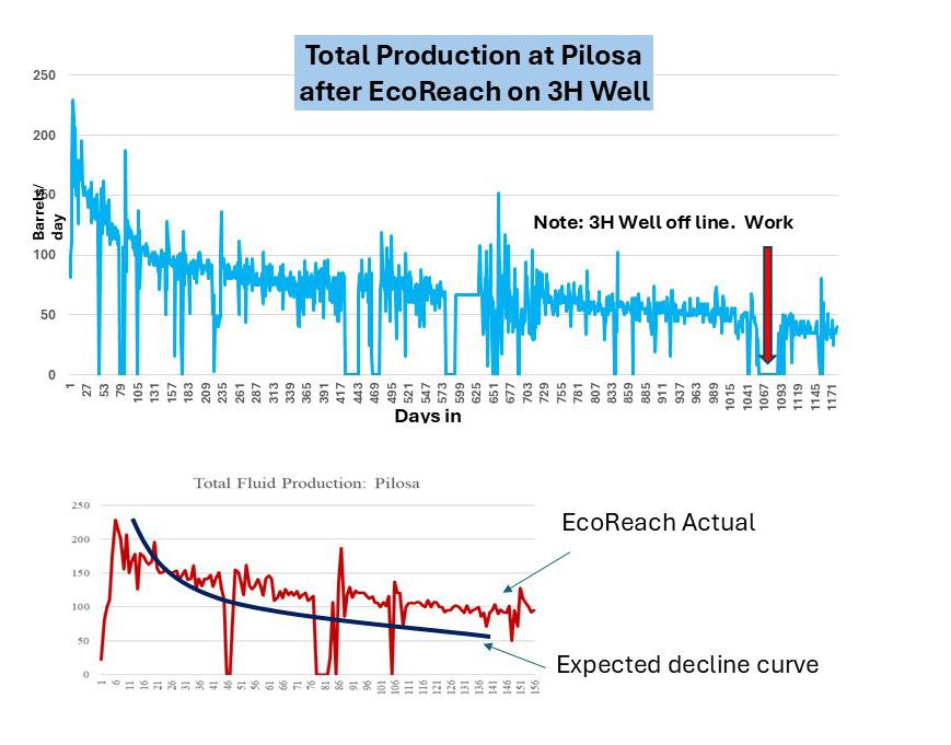
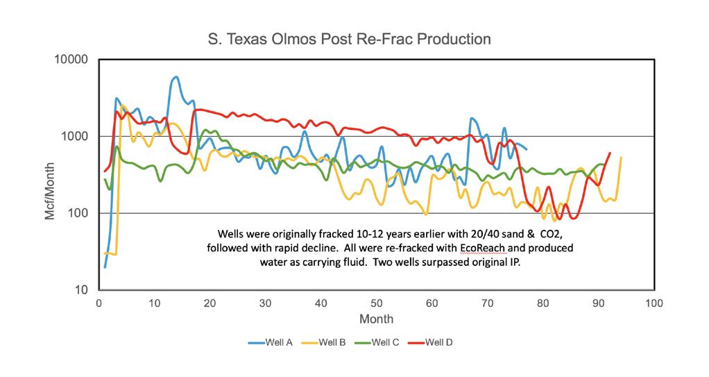
Figure 6. Sustained production uplift over five
after EcoReach re-fracks.
Figure 5. Production decline curve of EcoReach treated wells versus field average decline.
Figure 4. A smaller equipment footprint provides effective solutions for legacy well applications.
less water usage, and the repurposing of widely available proppant source provides a strong regulatory and environmental benefit.
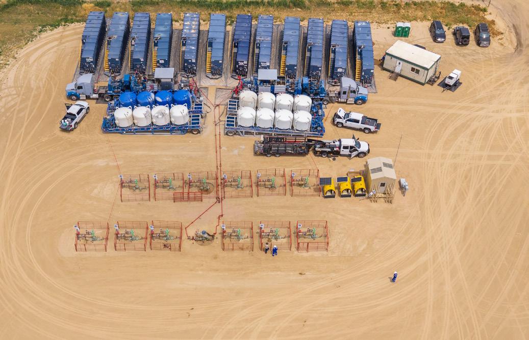
EcoReach operations may use as few as two cementing units compared to 20 - 25 larger fracturing pumps and associated equipment required for conventional treatments. Lower equipment intensity is associated with reduced fuel consumption and lower emissions related to transportation and pumping operations (Figure 4 demonstrates a fit for purpose equipment footprint utilising cementing pumps for legacy well fracks, re-fracks).
The fluid system used in EcoReach treatments typically consists of water and a small concentration of potassium chloride or other clay control salts. The absence of polymers and complex additives reduces chemical handling requirements and simplifies fluid management. In some applications, produced water from the same formation can be used, further reducing reliance on freshwater resources. The proppant tends to increase the pH of the fluid, which also reduces the need for biocides.
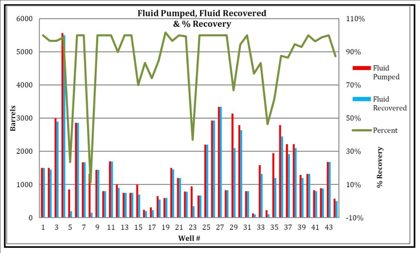
Water usage can be reduced by 50% or more compared to conventional methods due to higher proppant concentration levels. In addition, field experience shows that approximately 90% of injected fluid is recovered during flowback, compared to 30 - 35% in conventional sand fracturing operations (Figure 8).
These characteristics reduce surface footprint and overall environmental impact. Reduced equipment requirements also lower noise levels and limit exposure for personnel on site, supporting improved health and safety conditions during operations.
Economic considerations and industry adoption
EcoReach provides a cost-focused approach to production enhancement by reducing operational requirements while improving reservoir performance. As shown in Figures 5 and 6, wells treated with EcoReach are exhibiting uplift in the production with flatter decline
curves and sustained production beyond the field average of non treated EcoReach wells. The ability to execute treatments with lower horsepower equipment and simplified logistics contributes to more economical operations, particularly in legacy or marginal wells.
The system enables operators to economically stimulate wells with low production rates. For example, a well producing approximately 5 bpd of oil can be increased 3 - 5 times, with associated treatment costs potentially recovered within two to three months for oil wells. Gas wells with marginal payout periods are typically in the range of seven to nine months, depending on market conditions and gas composition.
Production performance across field applications has shown consistent uplift. Reported results include average production increases in the range of three to five times, with specific cases demonstrating five to seven times improvement in Olmos, Texas, US, wells and up to twelve times in South Texas Wilcox formations. In some gas wells, production has returned to original initial production levels after more than 10 years of decline, with certain wells exceeding original performance.
Decline curve performance has also shown measurable improvement. Field data indicate production curve improvements of about 15 - 30% over time, with sustained production observed for periods of three to seven years in multiple fields.
The ability to deploy treatments through existing tubing or work strings further reduces costs by limiting equipment mobilisation and minimising operational disruption. This makes the technology applicable to both new wells and re-stimulation of existing assets, including wells that may not justify conventional high-intensity treatments.
Adoption of new completion technologies is influenced by established industry practices. Operators typically require demonstrated field performance across multiple wells and reservoir types before integrating new approaches into standard operations.
As a result, deployment strategies often involve pilot projects and phased implementation, supporting the development of a broader performance record across different basins and applications. This approach allows operators to evaluate performance under specific reservoir conditions before expanding use more broadly.
Outlook for production optimisation
EcoReach reflects a broader shift in completion strategy toward improving reservoir connectivity while reducing operational challenges. Its ability to access complex fracture networks and enhance reservoir contact supports a more targeted and efficient approach to production optimisation aligned with evolving industry priorities.
Field applications continue to expand across multiple reservoir types, geographies, and operating environments throughout the United States and international markets. This growing body of operational data is improving the industry’s understanding of how broad sieved non-synthetic microproppant systems perform under varying reservoir conditions and completion designs.
As deployment experience increases, operators are gaining additional insight into the role Broad Sieved microproppants can play in enhancing fracture complexity, supporting hydrocarbon recovery, and improving long-term production behaviour beyond initial production metrics alone.
With operators increasingly focused on balancing efficiency, economics, and environmental performance, completion technologies capable of reducing operational intensity while improving reservoir access are expected to play an increasingly important role in the future evolution of well development strategies.
Figure 7. Plastic viscosity and apparent viscosity as a function of solids loading.
Figure 8. Percentage of slurry transport fluid recovered with post job flow back.
Hu Dai, PhD, Modelling lead at LINQX LLC, USA, discusses enhancing geothermal well cementing design using advanced cementing software.
ementing is essential in geothermal well construction as it provides a strong seal between the wellbore and surrounding formations, preventing fluid migration and reservoir contamination. It also supports the casing, protecting it from collapse under high pressure and temperature conditions common in geothermal environments. Cementing
isolates different layers within the well, ensuring proper fluid flow control and effective heat extraction from the targeted reservoir. With geothermal wells exposed to extreme conditions, the right cement type and proper execution are crucial for well integrity and longevity, making cementing a critical step in safe and efficient geothermal energy production.
Geothermal wells and conventional oil/gas wells differ primarily in their purpose, reservoir conditions, and environmental impacts. Oil and gas wells target hydrocarbon reservoirs, extracting oil or
natural gas, often from depths of 3 - 6 km or more. In contrast, geothermal wells are drilled to extract heat from the Earth’s crust, used for power generation or direct heating, with temperatures ranging from 150°C to 350°C. In well design, geothermal wells need specialised casings to handle high temperatures and corrosive fluids. With respect to environmental impacts, geothermal energy is a renewable, low-emission source, but it can involve water usage and mineral disposal issues. Table 1 summarises the differences between geothermal wells and oil and gas wells.
While the general cementing procedure for both geothermal and oil and gas wells involves similar steps, the extreme temperatures, chemical environments, and long-term performance considerations for geothermal wells require specialised cementing practices to ensure well integrity over time. The work of Payam Allahvirdizadeh provides a comprehensive review of geothermal wells focusing on well integrity issues.1 Salim (et al) discussed various aspects of cementing procedures and technologies for geothermal wells.2
Challenges in geothermal well cementing
The most critical issues for geothermal wells include the following: circulation loss and thick filter cake probably reducing cement formation bond strength; high temperature resulting in strength retrogression of the cement; and presence of corrosive components like CO2.2, 3
Circulation loss and thick filter cake reducing cement bond strength
Circulation loss occurs when drilling fluids or cement slurry leak into permeable formations instead of returning to surface. This can lead to incomplete or uneven cement placement, leaving voids in the annulus and weakening the bond between casing and formation. A buildup of drilled solids and mud on the formation wall, known as filter cake, can also impair bonding. If the filter cake is thick or poorly removed, it reduces cement adhesion to the rock. Poor bonding compromises zonal isolation, potentially causing fluid migration, reduced well integrity, and even wellbore collapse.
High temperature causing cement strength retrogression
Geothermal wells often exceed 200°C (392°F). Cement is designed to develop strength within a specific temperature range, but at high temperatures it may undergo strength retrogression, losing strength over time due to degradation of key compounds such as tricalcium silicate (C3S). Elevated temperatures accelerate hydration, causing faster setting but a less stable structure. This weakens bonding to casing and formation, increasing leakage risk and threatening well integrity. High-temperature-resistant cements and additives are used, though extreme geothermal conditions can still limit long-term performance.
Cement formulation
Fluid migration
Additives
Well type
High-temperature resistant cements (e.g. silica-based)
Emphasis on preventing fluid loss and ensuring thermal stability
High-temperature retarders, lightweight cements, expanding agents
Heat extraction or fluid injection wells
Standard API cement classes
Focus on preventing hydrocarbon or water migration
Standard additives (e.g. retarders, accelerators)
Hydrocarbon production or injection wells
Corrosive components such as CO2
Geothermal fluids often contain corrosive species such as carbon dioxide (CO2), hydrogen sulphide (H2S), and dissolved salts, which accelerate cement and casing degradation. CO2 dissolves in water to form
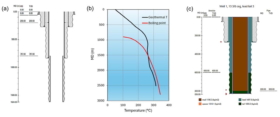
Figure 1. (a) Wellbore structure and (b) the static temperature profile of the example geothermal well; (c) the cement job of the 13 3/8 casing using lead and tail cements.
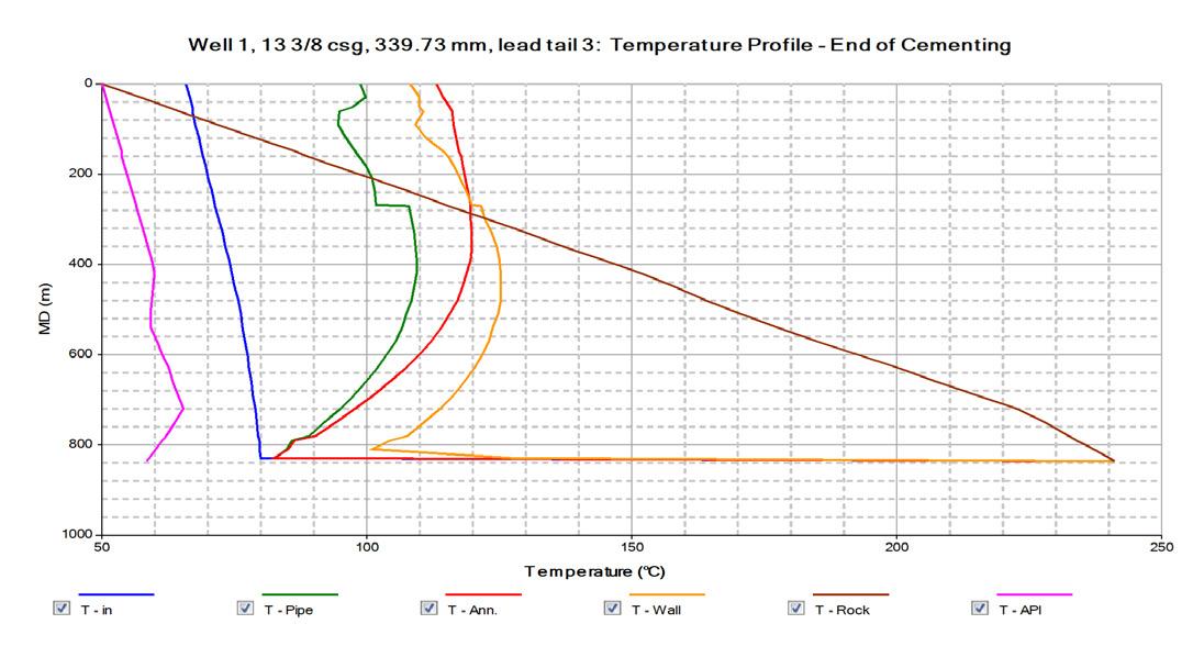
Figure 2. Temperature profile at the end of cementing job for the 13.375 casing.
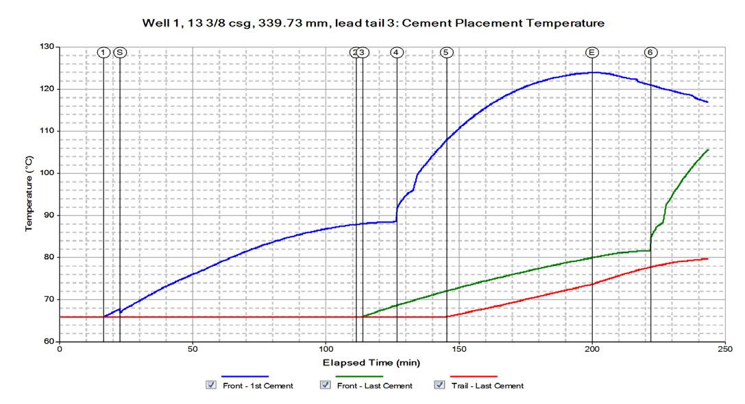
Figure 3. Temperature changes of the cement slurries during placement.
Table 1. Comparison between geothermal wells and oil and gas wells.
carbonic acid (H2CO3), lowering pH and causing acidic corrosion that weakens cement and reduces bond strength over time. High temperature and pressure increase CO2 solubility, worsening degradation. Specialised sulfurresistant or CO2-resistant cement systems are used, but controlling corrosive gases remains a major geothermal cementing challenge.
The role of cementing software in geothermal projects
Cementing software is essential in modern well construction. With advanced modelling capabilities, they support cementing design for oil, gas, and challenging geothermal wells. Take CEMPRO/CEMLife for example, important software features benefiting geothermal well job planning include:
Wellbore temperature modelling
The software uses a transient full-well heat transfer model to predict cementing temperatures accurately, even under extreme temperatures, accounting for complicated wellbore structure, fluids, lithology, and operation conditions.
Temperature- and pressure-dependent properties
The HPHT feature calculates rheological and density changes of cement slurries and other fluids, enabling accurate simulation of downhole ECD and temperature.
Acid-resistant casing database
Originally developed for CCUS wells exposed to long-term CO2, it benefits geothermal applications as it allows selection of corrosion-resistant casing materials.
Cement design optimisation
CEMLife applies a multi-layer stress model to evaluate mechanical and thermal performance of cement, casing, and rock, supporting efficient integrity analysis.
Cement placement simulation
An advanced displacement model accurately predicts annular flow behaviour, mud channeling, and contamination. It is especially important for challenging jobs of geothermal wells where cementing to surface is often needed.
Reverse circulation planning
Reverse circulation can improve placement control and reduce losses in fractured or high-temperature formations. This can be simulated in the software.
Case study
Real-world example in geothermal cementing
In this study, we created an example using real world data from a geothermal field developed in Indonesia.4 The project was developed to extract steam to generate and provide electricity. Well history suggested zonal isolation problems were due to structural failure of the conventional cement sheaths used, ineffective cement slurry placement by poor hole cleaning and ineffective removal of drill cuttings from the well during the hole cleaning.
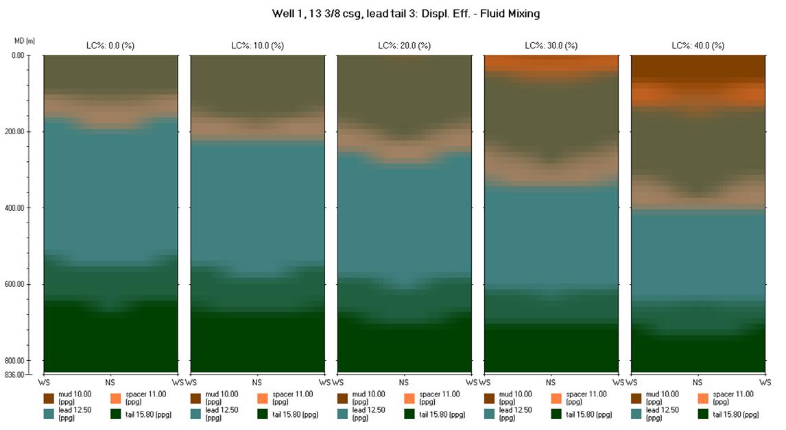
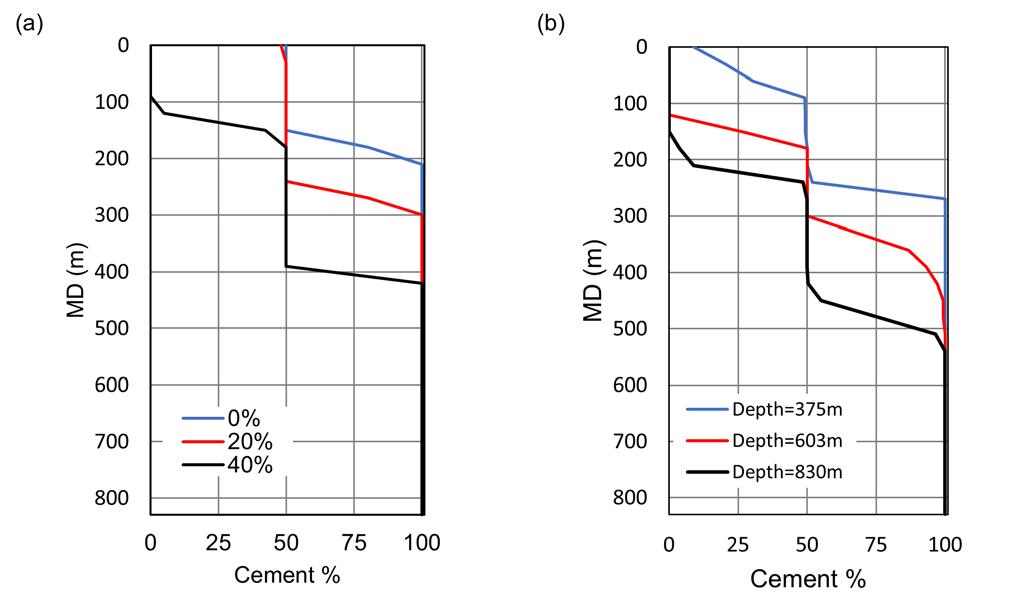
Figure 6. Sensitivity study of displacement efficiency during cementing of 13 3/8-casing under different lost return rates. Loss occurs at 830 m.
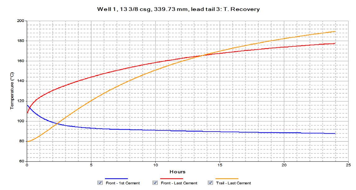
Figure 4. Cement temperature recovery during wait-on-cement.
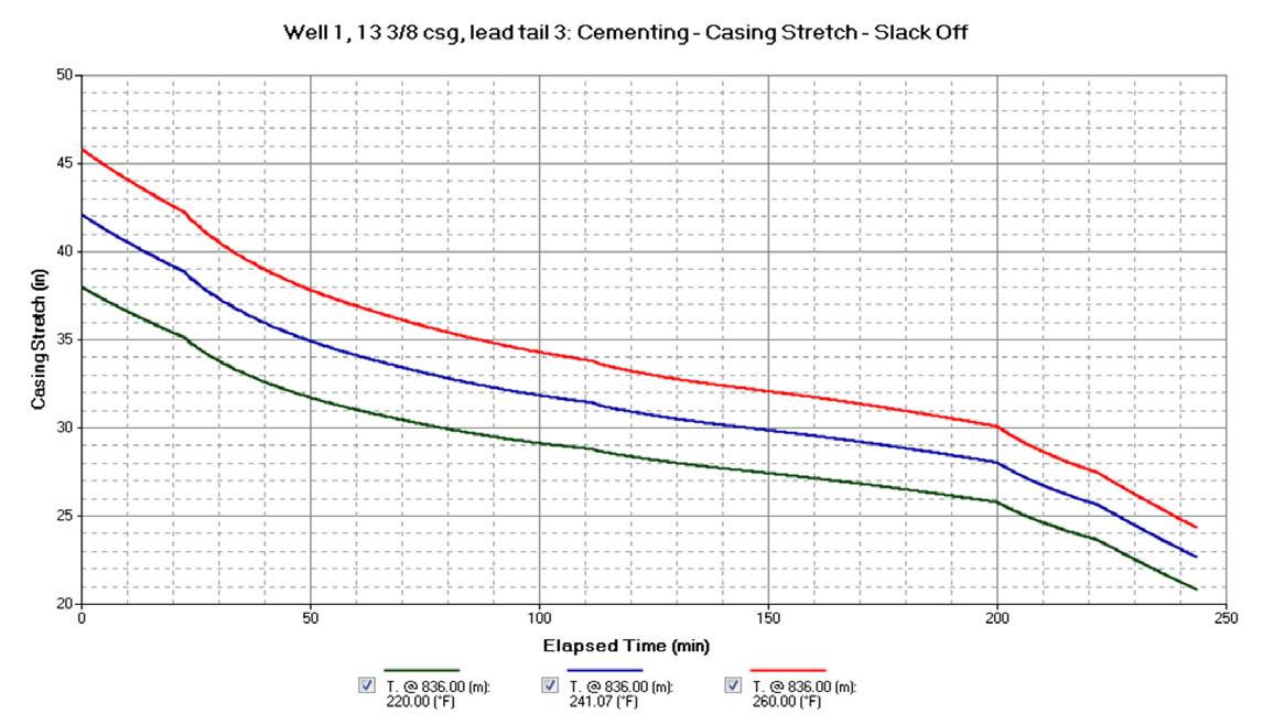
Figure 5. Sensitivity study of casing stretch during cementing under different static temperatures.
Table 2. Mechanical and thermal properties used in the model
The wellbore structure and the geothermal temperature profile are shown in Figure 1. The static temperature at the well bottom exceeds 260°C. In this study, we focus on the cement job of the 13 3/8 casing set at 830 m. The job used a conventional lead and tail cement slurry system. Figure 1(c) shows the planned fluid positions after cement placement. The pumping schedule uses a rate of 3 bpm for cement placement and 4 bpm for displacement. Since lost return was common in the field yet measurements are not available, a 20% lost circulation near the well bottom is assumed in the base case for the study.
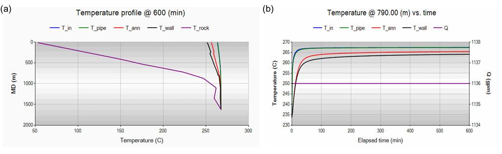
Using CEMPRO for temperature assurance during cementing. Although not very deep, the 13 3/8 casing job has a high BHST at approximately 240°C. Accurate prediction of BHCT is critical because thickening time, compressive strength development, and
rheological properties of cement slurries are all strongly influenced by temperature. The simulation shows a BHCT of approximately 82°C, higher than API-based estimation by over 20°C (Figure 2). Using CEMPRO to predict the transient temperature of front and trail of slurries provides direct guidance for lab tests of selected cement systems (Figure 3). The first sack temperature reaches 124°C during the job. During WOC, the trail of cement can recover to 190 °C in 24 h (Figure 4), which will impact curing and its compressive strength development.
High temperature in geothermal wells can cause excessive casing stretch during the cement job and during the production if casing is not well bonded. This study reveals a 42 in. stretch accounted at the beginning of job, and a 4 in. increasing of total casing stretch if BHST is increased by 20°C in the example (Figure 5). This is concerning during cementing if rathole length is short. On the other hand, it is reported that after the well produces, the casing temperature can increase by up to 300°C; the real wells in the field had 15 - 40 cm elongation based on wellhead growth measurement.4 This stretch should result from only part of the casing string with poor cement bond.
Using CEMPRO for lost circulation study
In the field, cement to top was planned, yet not achieved due to lost circulation in many wells; consequently, liner lap squeeze was performed. In the example, we vary the loss rate from 0 to 40% and perform the sensitivity study. Higher loss rate increases the amount of lost fluid, and reduces the annular velocity, thus it reduces the downhole ECD and pumping pressure.
Mud removal is simulated in CEMPRO with different loss conditions and a 70% casing standoff. With full return (zero loss), the simulation shows the clean TOC is located at slightly above 200 m, with mixed mud, spacer, and lead cement on top of it (Figure 6). This interface appears lower as loss rate increases; it is located at approximately 400 m with loss rate of 40%, when only pure mud is seen on the surface. Quantitative comparison of cement concentrations vs. depth for these cases are shown in Figure 7, where we also show the influence of loss depth.
Evaluating the loss conditions and simulating the displacement efficiency prior to cementing will benefit the job design. One can increase the volume of cement, improve the pumping schedule, or adjust fluid properties to ensure bond quality.
Using CEMLife for cement and casing failure analysis
In this project, conventional sealants were used in Phase 1 and an optimised elastic thermal cement system was used for enhanced life of well in Phase 2. The Young’s modulus value of the enhanced cement from the tests is 0.393 million psi, much lower than a typical unmodified Young’s modulus value of 1.5 million psi. Cement parameters used in the CEMLife model are listed in Table 2. The rock type used in the model is andesite and its properties are found in the work of Masri et al; the casing is 68 ppf K-55 steel, and the open hole size for the casing is 17.25 in.5 We examine the integrity at a depth of 790 m, slightly above the casing shoe.
We first evaluate the temperature change during production using CTEMP, another temperature model often used in drilling and production. We assume only liquid water exists inside the production tubing and the production flow rate is 4.3 m3/min. Based on previous analysis, the temperature at 790 m after cementing is about 89°C, and it will recover to static temperature of 234°C. The hot water is produced from the well bottom at 1624 m, and its temperature is 267°C. The simulation shows a quick increase of wellbore wall temperature to 264°C in 10 h; and the increase mostly occurs during
Figure 9. Cement integrity after increasing temperature by 30°C in 1 h.
Figure 10. Cement integrity after increasing temperature linearly by 30°C in 10 h.
Figure 8. (a) Simulated temperature profile after 10 h of production; (b) simulated temperature history at 790 m.
Figure 7. Simulated cement percentage profiles after displacement. (a) at different loss rates; (b) at different loss depths (loss rate is fixed at 50%).
the first hour. The temperatures of the tubing fluid and the static annular fluid are only slightly higher than the wall temperature, as seen in Figure 8.
Next, we examine the production-induced cement sheath failure risk by considering a temperature change of 30°C (from 234°C to 264°C) in the software. Using the conventional 15.8 ppg tail cement, stress analysis in CEMLife predicted a compression failure warning and traction failure (Figure 9). Quick temperature change causes expansion of cement; and because heat is transferred outward from inside, the formation expands slower and thus compresses the cement inward from outside, producing a shear failure risk at the same time. If the wellbore is heat up slower, as we consider the same temperature increase but in 10 h duration, there is no risk of compression but still with traction failure, as seen in Figure 10. This is because rock expands more simultaneously with the cement sheath.
On the other hand, if we replace conventional cement with the enhanced thermal cement system and perform the same modelling, the software predicted no failure at all (Figure 11), which is consistent with the field record. Based on the sensitivity analysis in the software, the cement should have a Young’ modulus lower than 0.78 million psi.
Casing yield is also analysed and no risk is predicted. In the real world, casing integrity is more complicated; casing collapse and buckling were reported in the field. An analysis requires information of annulus pressure due to compression of trapped fluid under thermal effect, and the details of cement bond and mud removal. Consider, collapse strength of the 13 3/8 casing is estimated to be approximately 15 MPa, if there is a 60 bar wellbore pressure during production, the casing could collapse if the annular pressure is going above 21 MPa due to high temperature.
Figure 11. Cement integrity after increasing 30°C in 1 h using improved elastic thermal cement.
Conclusion
Cementing is critical for ensuring the integrity and longevity of geothermal wells. While geothermal wells face unique challenges, advanced software tools help optimise cement design, improve accuracy, and mitigate risks. These technologies are essential for safe, efficient, and reliable geothermal well construction. Using a detailed case study based on real wells in this paper we further demonstrated the practical application of modelling and benefits of these cementing solutions in real-world geothermal projects.
References
1. Payam Allahvirdizadeh, 2020. A review on geothermal wells: Well integrity issues, Journal of Cleaner Production, Volume 275. https://doi.org/10.1016/j. jclepro.2020.124009.
2. Salim, Prisca; Amani, Mahmood, 2013. Principal Points in cementing geothermal wells, 1, s.l. : CSCanada Adv. Petrol. Explor. Dev. 5, 77e91, 1925-5438.
3. Shryock, S.H. & Smith, D.K. (1980): Geothermal Cementing - The State-of-the-Art, C-1274. Halliburton Services paper No. C-1274, Duncan.
4. Ravi, Krishna, et al., 2008. Advanced cement systems used to improve geothermal well reliability in java. s.l.. In: SPE Annual Technical Conference and Exhibition, 21-24 September, Denver, Colorado, USA. Society of Petroleum Engineers.
5. Asrizal Masri et al, 2015. Structural Permeability Assessment Using Geological Structural Model Integrated with 3D Geomechanical Study and Discrete Facture Network Model in Wayang Windu Geothermal Field, West Java, Indonesia. Fourtieth Workshop on Geothermal Reservoir Engineering. Stanford University, January 26-28, 2015, SGP-TR-204.
CCS Forum 2026: CCUS Panel Discussion Pt. 2
This episode of the World Pipelines Podcast is the second of a two-part series on CCUS in the cement sector, and what that means for CCS pipelines in the UK. Featuring the audience Q&A from the CCUS panel discussion, as shared by delegates at the World Pipelines CCS Forum 2026 and World Cement’s EnviroTech 2026.
The Q&A sees event and pipeline delegates ask our panel questions about infrastructure, investment confidence, timelines, risk, regulation, storage, industrial decarbonisation, and the practical realities of delivering CCS in the UK.
CATCH UP ON RECENT EPISODES
• CCS Forum 2026 CCUS Panel Discussion Pt. 1
• YPI
• Hunton Andrews Kurth LLP
John Tillema, Growth Hub Director for Process Automation at IMI, questions how the upstream sector can juggle efficiency, sustainability, and reliability challenges all while making stakeholders happy and turning a profit.
he upstream sector faces a balancing act. How does it juggle efficiency, sustainability and reliability challenges all while making stakeholders happy and turning a profit? The answer lies in market-led initiatives, such as IMI’s Growth Hub innovation engine.
Streamlining the upstream
The upstream sector needs innovation now more than ever before. It is contending with a myriad of market pressures, energy transition challenges and digitalisation dilemmas. There is also a clear paradigm that exists in the sector. While upstream operations are pivotal to the global energy supply, the sector is at the heart of the need to reduce reliance on fossil fuels. The duality of these challenges requires new ideas. And the best ideas come from those who work in the sector first-hand.
IMI’s Growth Hub was created as a catalyst to help ease pressures on the upstream sector. Originally developed from a growth accelerator process first tested by IMI in 2018, Growth Hub has since transformed into a series of stagegated processes committed to finding solutions to real industry problems, proving their feasibility and scaling them into sustainable offerings. Not only has it developed genuine, cutting-edge solutions, but it has in the process, generated
£125 million of orders in 2024 alone for IMI’s Process Automation sector.
The Growth Hub concept
As an innovation engine, the Growth Hub fosters entrepreneurial problem-solving from IMI’s strong customer relationship base to fast-forward good ideas and quickly kill off less viable ones. Sprint teams move quickly using a test and learn approach to create solutions to problems. Those concepts are then tested with customers at an early stage in the development process.
Ideas that are not successful at this stage are quickly withdrawn, ensuring only the ideas that offer significant value to customers are developed fully and launched to market. Practical ideas are key to achieving better results in today’s power generation plants. Optimising performance, improving the reliability and availability of plant assets and minimising maintenance times are goals that will be familiar to most site managers.
However, IMI’s Growth Hub philosophy is not just focused on these short-term changes, as valuable as they can be. Instead, it also focuses on laying the groundwork for longer-term goals, such as automation, digitalisation and, perhaps most important of all, decarbonisation.
The key to identifying and filtering ideas that are not just theoretical but also work in practice, is industry knowledge and first-hand experience. That’s why the Growth Hub model works. By nurturing ideas from those who work in the upstream sector and understand challenges at an operational level, process automation specialists, such as those at IMI, can turn these ideas into reality. And if it doesn’t work – the trial is halted before any unnecessary time and money is invested. That’s why killing off unsuccessful ideas quickly is as important as advancing good ideas quickly.
Tackling common industry challenges
The exciting thing about the Growth Hub approach is its ability to create solutions to a variety of common problems that blight upstream sector operations. These results are testament to the effectiveness of customerled innovation in the upstream sector. Since its launch, several solutions developed in Growth Hub are now delivered through IMI’s Process Automation sector. This includes Retrofit3D™ additive, manufactured valve components, EroSolve Wet Steam valve trim components, IMI InSynt study reports and IMI VIVO hydrogen electrolysers.
Take Retrofit3D for example. Traditional like-forlike valve replacements can be expensive and complex, especially for welded inline valves. This is due to additional scheduling, cutting, re-welding, engineering, and post-weld inspection costs. The process is costly in both time and money and can have severe consequences for power plant managers. To solve this dilemma, Retrofit3D was developed through the Growth Hub approach to eliminate problems in control valves without the need to replace the entire valve.
Retrofit3D is a customised trim solution that fits into existing valve bodies without changing the body or top works. The trim uses DRAG® technology to address root causes of valve issues by directing fluid through a multi-
Figure 1. Growth Hub.
Figure 2. As an innovation engine, the Growth Hub fosters entrepreneurial problem-solving from IMI’s strong customer relationship base.
Figure 3. IMI’s Growth Hub shows that shaping a more efficient, sustainable upstream industry will come by listening to the problems faced by engineers.
stage, multi-path trim to reduce differential pressure. Its design eliminates erosion, vibration and noise, ensuring enhanced valve performance.
The solution is proving successful in the power generation industry, where retrofitting is significantly more cost-effective than complete valve replacement which is a significant, capital expense project. The fact that the process is quick has led to far less plant downtime while also delivering greater process control. Instead of having to completely replace a valve, plant managers can simply change the part numbers in their inventory system and drop in a new trim set.
Another product which has transformed the process and power sector is EroSolve Wet Steam. The product recently passed the milestone of 750 installations worldwide and has been successfully integrated in various process and power plants, leading to improved efficiency and reduced operational costs.
Wet steam is formed during power plant start-up primarily due to insufficient drain, improper prewarming and incorrect operational logic within the plant. This issue is often difficult to fix without addressing plant design and layout to fix poor drain or incorrect operational logic within the plant. The trim upgrade is a novel way in which the plant can operate more efficiently without having to upgrade or redesign the whole system.
The primary function of the EroSolve Wet Steam solution is to prevent condensate erosion from damaging turbine by-pass valve internals, specifically during initial plant start up. It enhances valve performance by optimising droplet impingement angles and using erosion-resistant materials to prolong the life of valve trim components.
A real-world impact
While the Growth Hub has enabled innovations which have made positive impacts directly in the upstream sector and power plants, there have also been solutions which have tackled wider, decarbonising issues. The VIVO Electrolyser was developed by a Growth Hub team to aid the energy transition – specifically the use of hydrogen.
The Paris Agreement 2015 states that hydrogen will be a key part of ensuring economies can achieve carbon neutrality by 2050. But it’s safe to say the world’s economies are a way of making this commitment a reality.
Part of the reason for slow adoption of hydrogen into production is a lack of access to the right technology, especially for organisations operating in more remote geographical areas where there is an abundance of renewable energy resources. That’s why one of the major focuses at IMI has been the expansion of its portfolio and solutions throughout the hydrogen value chain. As a result, the Growth Hub team developed a low-risk solution for decarbonising on-site operations.
This takes the form of the VIVO Electrolyser which converts water into hydrogen using renewable electricity. As a turnkey solution, the electrolyser acts as a complete, packaged solution that includes the electrolyser itself as well as control and storage. This technology will be
critical in decarbonising manufacturing sectors that cannot be electrified, which was the reason behind this particular Growth Hub innovation. The electrolyser’s turnkey configuration makes it adaptable to customer specifications and allows for tailored designs that match the specific requirements of each facility. This allows the solution to be scaled – a necessary requirement for any innovation that has been designed to solve a decarbonisation problem.
Unlocking the upstream opportunity
IMI’s Growth Hub has proven that shaping a more efficient, sustainable upstream industry will be based on listening to the problems faced by engineers and involving them in finding solutions.
Innovation that is rooted in customer insight drives real-world, measurable impact and promises to ease the competing pressures on critical sectors, such as those facing the upstream. It also offers manufacturers a golden opportunity. By designing the answers to an ever-changing landscape, solution providers, such as IMI, can make themselves indispensable and place conscientious productdesign at the heart of pressing industry issues.
Figure 4. IMI’s Growth Hub was created as a catalyst to help ease pressures on the upstream sector.
Figure 5. The VIVO Electrolyser was developed by a Growth Hub team to aid the energy transition – specifically the use of hydrogen.
Mark Skene, Senior Consultant Engineer, Xodus, examines using digital integration to improve efficiency on the Triton FPSO.
he increasing importance of digitalisation and automation across all sectors is as critical and ever-present now as it ever has been, no more so than in the oil and gas industry.
Being digitally progressive and making use of groundbreaking technology has proven over time to ensure that the sector continues to strive forward and deliver vital improvements in health and safety, efficiency, sustainability and ultimately drive industry growth.
Despite a sustainability drive and the need to attain well publicised net zero targets, the oil and gas industry remains a
critical component of the global energy system - ensuring that the industry continues to progress is imperative. The most effective energy transition will still include oil and gas operations for years to come, and that brings both challenges and opportunities that new technology and an experienced workforce will meet head on.
Much of the opportunity stems from how the industry can improve efficiency through digitalisation. If new tech can create more efficient workflows that are both cost-saving and timesaving, then there are universal and substantial wins that can be achieved. XAMIN Integrity Management (IM), a digital platform developed by collaboration between the in-house software development team at Xodus and the engineering subject matter experts, has proven to deliver just that. In one case, a client reduced resource spend by approximately 52%, saving approximately £800 000. This was achieved by XAMIN data insights highlighting the ability to optimise inspections and interventions so that they were planned only when truly needed rather than the continuing with the status quo out of habit and lack of informed intelligence.
Greater understanding and utilisation of data is now an essential element of industry growth and the way in which it
has advanced has been exponential. Not only is historic and current data better understood, but now real-time analysis reduces risks while enabling quicker, more reliable, informed and data-driven decision-making. It is more accurate and more collaborative too, looping in separate teams and partners both on and offshore instantly.
From a downtime perspective, the data and corresponding status of assets can be constantly monitored to reduce the need for pre-scheduled and potentially unnecessary maintenance – again emphasising the benefits of digitalisation to save valuable costs and time. This type of data analysis of course has benefits in others way too, optimising both onshore and offshore production and performance by reliably understanding the ‘health’ of assets. Harnessed data can not only be used to influence current operations, but also to simulate future conditions and ensure teams are prepared for a wide range of unpredictable external factors – something that in days gone by would have been impossible and instead be a case of either operating through unknown risk or facing unplanned downtime.
Moreover, the impressive growth of advanced analytics, including the use of artificial intelligence (AI) within that, is enhancing modelling and forecasting, which in turn positively contributes towards improving recovery factors and extending the economic life of mature North Sea fields.
Collaboration is often at the heart of industrial growth and the same can be said in oil and gas. As the boundaries of digitalisation and automation grow, as do the possibilities when teams work together to greater utilise shared resources and technology. A founding principle of XAMIN IM was that it would be built in collaboration with both its users to help solve the problems they faced, and with the wider industry to bring insights from other digital platforms together, ultimately acting as one single source of truth for assets. This is the true value of a platform like XAMIN IM and why it can be of fundamental importance in a sector that continues to digitally modernise.
Case study: XAMIN
A persistent challenge in offshore oil and gas operations is aligning integrity management with maintenance and construction activities. These functions have often been managed in organisational and digital silos, resulting in inefficiencies that raise costs, increase risk and reduce transparency across teams.
Bridging disconnected systems
Dana Petroleum encountered this issue on the Triton floating production, storage and offloading (FPSO) vessel. The company’s Integrity Management
Figure 1. Digitalisation of offshore processes is increasingly common.
Figure 2. Integration is key to ensuring seamless synchronisation between platforms.
(IM) team relied on Xodus’ XAMIN IM platform to monitor asset health and track required maintenance. In parallel, offshore construction activities were supported through VISION – Global Design Innovation’s (GDi, an Oceaneering Company) digital asset management application. VISION provided a 3D contextualised model of the FPSO, informed by high-resolution laser scan data, to support planning and visualisation.
Although both systems were essential, they operated independently. Data transfer between them required manual effort, introducing duplication, delays and potential errors. This also meant that planning often relied on static spreadsheets instead of an accurate digital representation of the asset, leading to suboptimal task prioritisation.
Dana recognised the need for a unified solution capable of providing real-time, accurate data across both integrity and planning domains, while also reducing the administrative burden.
Integration approach
To resolve these challenges, Dana initiated a joint effort with Xodus and GDi to connect XAMIN IM and VISION into a single integrated workflow. Within six weeks, the teams aligned objectives, addressed connectivity and data synchronisation challenges, and built a bi-directional data bridge between the two platforms.
This was enabled through an Application Programming Interface (API) that ensured the security and integrity of IM data, while making it accessible within VISION’s planning environment. Integrity issues recorded in XAMIN IM were automatically visible in VISION, geolocated within the 3D model and linked back to their source records.
With this integration, planners could group and prioritise tasks by proximity, severity, or other criteria, while working from a reliable, visual representation of the FPSO. Importantly, XAMIN IM remained the system of record for all integrity data, ensuring planning decisions were grounded in verified, current information.
Operational benefits
Following implementation, Dana reported several measurable improvements. Manual duplication of data was reduced, freeing resources for higher-value activities. Planning cycles became more efficient, as tasks could be scheduled and visualised in alignment with the physical layout of the FPSO. This, in turn, improved campaign planning, reduced preparation time, and enhanced resource forecasting.
According to Dana’s Offshore Construction Supervisor, the reduction in planning effort has been substantial, providing new capability to coordinate campaigns more effectively.
Broader implications
The Triton FPSO project demonstrates how integration between digital systems can improve coordination between onshore planning and offshore execution. Beyond the technical implementation, the initiative highlights the value of cross-organisational collaboration in addressing persistent operational inefficiencies.
Dana, Xodus and GDi’s approach, linking existing systems through an API bridge rather than replacing them, illustrates a pragmatic and cost-effective model for other operators. The project also underscores how integration initiatives can extend further, connecting with additional digital systems to deliver even greater operational alignment.
A next-generation model
As offshore assets age and operational complexity grows, the ability to connect disparate digital systems becomes increasingly important. By leveraging available tools and focusing on integration, operators can reduce inefficiencies, enhance data fidelity and improve safety outcomes.
The Triton FPSO project provides an example of how targeted digital integration can deliver immediate benefits, while laying the groundwork for broader digital transformation across offshore operations.