AB
AC
20
HP 20
HP 20
HP 20
HB
HP 20
HP 20
HP 20
30°
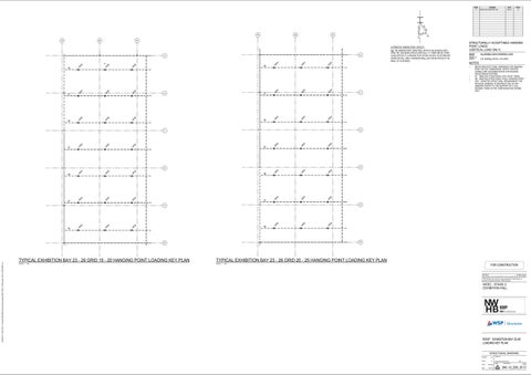
ALTERNATIVE HANGING POINT CAPACITY N.B. THE HANGING POINT CAPACITIES LISTED IN THE SCHEDULE RELY UPON THE LOAD BEING APPLIED VERTICALLY. IF THERE ARE NO OTHER LOADS APPLIED TO A HANGING POINT WITHIN THE MFS, FB OR GREATER EXHIBITION HALL AREA, A MAXIMUM 500kg LOAD CAN BE APPLIED AT AN ANGLE OF 30 DEGREES.
STRUCTURALLY ACCEPTABLE HANGING POINT LOADS (VERTICAL LOAD ONLY) MARK (S.W.L.) HP20
HP 20
HP 20
HP 20
HP 20
HP 20 HP 20
HP 20
HP 20 HP 20
HB
HP 20
HP 20 HP 20
HB
RT
16
•
23
HP 20
HP 20
HP 20
HP 20
HP 20 HP 20
HP 20
HP 20 HP 20
RT
HP 20
HP 20
HB
HP 20
RT
24
HP 20
25
20
16/06/2017 4:00:25 PM C:\Users\AURC02551\Documents\Autodesk\3942_MCEC_WSPcentral_RS16_AURC02551.rvt
HP 20
HB
HP 20
HP 20
HP 20
HP 20
19
HB
REFER ARCHITECTURAL DRAWINGS FOR HANGING POINT SETOUT DIMENSIONS. REFER THEATRE CONSULTANT DOCUMENTATION FOR RIGGING TRUSS SPECIFICATIONS. RT : DENOTES STRUCTURAL STEL ROOF TRUSS HB : DENOTES STRUCTURAL STEEL HANGING POINT HP4* : DENOTES STRUCTURAL REQUIREMENT FOR PHYSICAL SIGNAGE TO RESTRICT USE OF HP4 HANGING POINTS TO THE SUPPORT OF A 9.0m RIGGING TRUSS IN THE CONFIGURATION SHOWN ONLY.
HP 20
HP 20
HP 20
HP 20
HP 20
HP 20
RT
18
HB
2.0t (2000kg) ON 6m x 6m GRID
22
17
RT
21
ALLOWABLE SAFE WORKING LOAD
NOTES:
• • •
RT
INTIAL SL
AC
15
HB
DATE 16.06.17
kg 500
AA
AB
REVISION ISSUED FOR CONSTRUCTION
X. MA
AA
CL OF HANGING BEAM
ISSUE C1
TYPICAL EXHIBITION BAY 23 - 26 GRID 15 - 20 HANGING POINT LOADING KEY PLAN
TYPICAL EXHIBITION BAY 23 - 26 GRID 20 - 25 HANGING POINT LOADING KEY PLAN
SCALE 1 : 100
SCALE 1 : 100
FOR CONSTRUCTION COPYRIGHT All rights reserved. These drawings, plans and specifications and the copyright therein are the property of WSP Structures and must not be used, reproduced or copied wholly or in part without the written permission of WSP Structures.
MCEC - STAGE 2 EXHIBITION HALL
ROOF - EXHIBITION BAY 23-26 LOADING KEY PLAN STRUCTURAL DRAWING Designed
MS
Drawn
JX
Scale
As indicated
Date
MAR. 2017
Approved Project Engineer/Director North
Drawing No:
Date Issue
3942 S3_2500_09 C1