Exhibition Bays Engineering Report

Page 1

21

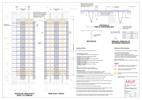
Rigging zone between truss and services zone denoted by blue arrow. Exhibition loads should be supported using beam clamps applied to the bottom flange of the beams, centered on the web.

20

Within the hatched zone, the load at rigging point F must be combined with the load at the adjacent rigging point (e.g., A, B, C, or D) when assessing compliance with the loading criteria - typical

Secondary beam

No rigging within services zone

F

F

E

A

B

E

A

B

E

A

B

Services zone - 7800 typical A

B

C

D

Main roof truss

F

6000 Typical

F

F

F

A

B

C

D

A

B

C

D

A

B

C

D

SECTION A-A TYPICAL STRUCTURAL BAY

Bridling permitted parallel to secondary beams. Refer to table for maximum load and angle restrictions.

A

B

-

A

E

B

E

A

B

E

A

B

E

A

B

A

E

A

E

A

A

B

C

B

C

B

A

B

C

D

A

B

C

D

A

B

A

B

C

B

C

D

A

B

A

B

C

D

E

A

B

A

B

C

D

A

E

A

E

F

F

B

A

B

A

F

F

B

C

B

C

F

F

F

0-9

Vertical load - refer loading criteria note 2

10-30

1000kg

31-45

700kg

46-60

500kg

>60

Not permitted

Reference Documentation

1. All loading advice refers to working (unfactored) loads.

1. Structural advice is based on the following existing documentation.

Notes: - Loads can be supported from concurrent rigging lines - Refer to note 3 for limitations for rigging in bridle arrangements

D

Max Load

Loading Criteria

i) Maximum load supported at any single location: 2000kg Conditions: A, B, C, D, E ≤ 2000kg ii) Maximum cumulative load supported by a main truss: 2000kg Conditions: A+B, C+D ≤ 2000kg iii) Maximum cumulative load supported within a typical structural bay: 2000kg Conditions: B+C ≤ 2000kg iv) Maximum load supported within an end structural bay: 2000kg Conditions: E+A ≤ 2000kg v) Maximum load supported by beams 0 and 14: 1000kg Conditions: F ≤ 1000kg

D

C

ϴ degrees

BRIDLING - PARALLEL TO SECONDARY BEAM (NTS)

2. Vertical Rigging Load Criteria: - The vertical rigging loads must not exceed the following criteria:

D

E

ϴ

Max Load Refer Table

B

D

SECTION B-B

Rigging line (13 total)

ϴ

No bridling permitted perpendicular to roof beams.

D

EXHIBITION HALL

External wall shown indicatively

Roof Line

Typical Structural Bay 18000 Nom

End Structural Bay 18000 Nom

F

B -

3. Bridling Load Criteria: - When bridling, the maximum load shall be reduced. Refer to Detail 1 for restrictions. - No additional loading (points A to F) is allowed concurrently with bridle loading. - The maximum angle for bridling is 60 degrees. For detailed guidelines, refer to Detail 1 of this sketch. 4. The maximum load allowance is based on the MEC Operating and Maintenance Manual For the Building - Part A, Section A.2.1. - The manual specifies that 2,000 kg can be supported by any of the secondary beams.

Ove Arup & Partners Consulting Engineers: - 7761/S1700/C - General Notes Steelwork - 7761/S1702/B - Exhibition Hall Secondary Steel Layout - 7761/S1703/B - Exhibition Hall Secondary Steel Typical Bay Layouts - 7761/S1707/C - Exhibition Hall Duct Support Layout & Details - 7761/S1732/B - Exhibition Hall Secondary Steel Details Sheet 2 Melbourne Exhibition Centre: - Operating and Maintenance Manual For The Building - Part A Section A.2.1

Legend

A

Denotes rigging point. Loads can be supported between truss and service tray. Refer section A for details. Denotes roof secondary beam (UB14 & UB20). Refer structural drawing S1703/B for details

Denotes main roof truss. Refer structural drawing S1703/B for details Denotes beams 0 and 14 (UB9). Refer structural drawing S1703/B for details

5. This advice is based on the assumption that exhibition loads are static in nature. 6. Exhibition loads are to be supported by roof secondary beams, not the main trusses. Roof secondary beams are shown indicatively in blue. 7. Exhibition loads should be supported using beam clamps applied to the bottom flange of the beams, centered on the web. Design of beam clamps by others. 8. This advice is based on loading applied to the roof beams only (blue). 9. This advice assumes no solar panels have been installed on the main roof. If solar panels are installed, this advice may be invalidated, and further engineering guidance should be sought. 10. This advice assumes that the weight of the operable walls is equal or less than the original specification. Future installation of heavier wall panels may invalidate advice and engineering guidance should be sought.

ROOF PLAN - GRID 20 TO 21 (GRID 1 TO 2 SIMILAR)

ROOF PLAN - TYPICAL

11. No materials are to be stored on the Exhibition Hall roof whilst exhibition loads are installed. Access for roof maintenance shall be limited to individuals and shall not exceed the equivalent of 7kg/m^2.

MEC - Exhibition Hall Roof Rigging Assessment

Exhibition Hall Rigging Loads ARP-SKT-ST-001 For Information

304112-00

1 of 2

NTS

02

JSD

28/08/2024

DY


Turn static files into dynamic content formats.

Create a flipbook
Exhibition Bays Engineering Report by Melbourne Convention and Exhibition Centre - Issuu