Instructions for shielded metal arc welding WARNING
Please pay attention to the safety instructions in the Operator's and Service Manuals concerned. Scope
These instructions have been provided to ensure that modifications or repairs involving welding onVolvo Wheel Loader"s machines will be of the highest quality.
These are general welding instructions that must be supplemented with drawings, sketches and specifications from Volvo CECustomerSupport
In cases where the use of MIG, TIG, Fluxcore or submerged arc welding is required, contact VCE Customer Support for approval
Welder competence, qualifications and requirements
Unless otherwise specified or approved, all welding must be carried out by a welder whose competence meets the requirements according to the AmericanWeldingSociety, Specification D1.1 or D14.3, or ASMEPressureVesselCode, Section IX.
Each country has its own welding standards and specifications. All welding must carried out by a competent welder in order to meet the requirements specified by the country where the work is to be carried out.
Base materials
Refer to drawings, sketches and specifications which are made available by VCE Customer Support.
Filler materials (Coated electrodes)
Electrode classification must be according designations on accompanying drawings, sketches or specifications which are made available by VCE Customer Support
The welding electrodes must meet the following requirements:
EN 499-95E 42 4 B 42 H5
Swedish National Standard 79SS 3211-H10
AWS A5. 1-91E 7018-M
DIN 1913-84E 51 55 B10 120
ISO 2560-73E 51 5 B 120 20 H
These electrodes may be used:
E 8018: AWS A5 5, class E 8018-D3
E 9018: AWS A5 5, class E 9018-D1 or E 9018-M
E 10018: AWS A5.5, class E 10018-D2 or E 10018-M
E 11018: AWS A5.5, class E 11018-M
OK 67.45 (EN 1600 E 18 8 Mn B, AWS A5.4) ESAB
OK 68 81 (EN 1600 E 29 9R 32,SFA7AWS A5 4) ESAB
Elgaloy Mix 18 (EN 1600 E 18 8 Mn R 53,AWS A5 4-92)), ELGA
Electrode sizes
The electrode size must be adapted and be suitable for the type of material, type of weld joint, welding position and other circumstances affecting the work
The maximum size of electrodes and current strength are as follows:
NOTE! Position
Flat/horizontal 100/150 175/225 225/275 350
Vertical 120/140 140/160 - -
Overhead 110/135 140/170 - -
6.35 mm (1/4") max. diameter for horizontal fillet welds.
6.35 mm (1/4") max. diameter for root passes or fillet welds made in the flat position and for weldjoints made in the flat position with backing bar (root passes) and with an root opening of 6.35 mm(1/4") or greater.
3.97 mm (5/32") max. diameter for welding made in the vertical and overhead positions.
Care and storage of electrodes
Electrodes in hermetically sealed containers may be used immediately from the container for a specific period of time afterthe container has been opened
Time periods are as follows:
E7018 -4 hours
E8018 -2 hours
E9018 -1 hours
E10018-30 minutes
E11018-30 minutes
All electrodes which are not used within the above specified times must be stored in an oven at a temperature of at least 121 ºCelsius (250 ºF)
Electrodes which have been exposed to the atmosphere for a longer time than specified above, must be dried for at least one hour at a temperature between 371and427 ºC (700 and 800ºF) before they are used.
Preparation of materials
The surface, which is to be welded, must be free from moisture, slag, rust, paint, grease, oil or other foreign material which prevent proper welding
In cases where original parts have been removed by carbon arc welding, all oxides, slag and carbon deposits must be removed by grinding to remove sharp undercuts, cracks, nicks or gouges. This is to be followed by welding and grinding if required to provide a smooth and even surface.
Assembling
Aligning parts:
Parts to be joined by fillet welding must be placed as close together as piratically possible. The distance between the two parts must normally not exceed 3.17mm(1/8"). If the distance exceeds1.58mm(1/16"), the leg of the filled weld must be increased by the distance between the parts
All parts must be supported to provide the best possible alignment between the parts and to minimise stresses on tack welds and root passes
Tack welds are subjected to the same quality requirements and limitations as the final welds
All tack welds must be thoroughly cleaned from slag prior to incorporating them in the final welds
Cracked or faulty tack welds must be removed by grinding prior to final welding.
Position
The pieces to be welded should be placed flat where possible
Preheating and temperature of the work pieces
Interpass temperature –the temperature throughout the material
The material to be welded must be preheated, when required, to reach a minimum preheating temperature which is specified in supplemental drawings, sketches and specifications supplied by VCE Customer Support
Unless otherwise specified, the temperature must not be less than 10ºC(50ºF)
The preheating temperature must be measured 75 mm(3") from the centre line of the weld and at the opposite side of the work piece from where the heat was supplied. This technique will assists in ensuring that the heat has penetrated through the material.
Maximum interpass temperature are 204ºC(400ºF) unless otherwise specified. If possible all welding should be carried out in an
order that balances the supplied heat during the progress of the welding
A device for measuring the surface temperature is to be used to check the preheating temperature and the interpass temperature throughout the material. In cases where temperature sensitive crayons are used, all remaining crayon residue or other contaminants must removed from the surface to be welded.
Welding must not be carried out when the workpiece is exposed to strong wind, draught or moisture
Electrical specifications
Use direct current, reverse polarity (electrode positive) at amperages and voltages recommended bythe electrode manufacturer
The ground connection must be safely secured as close to the point of welding as possible. Do not connect the ground connection so that the electrical current of the welding circuit has to pass across a bearing. For example, when welding on the front frame of the wheel loader, do not attach the ground connection to the rear frame
Welding technique
Electrode handling:
The arc length must be kept as small as possible during the entire welding work.
All welding beads, except vertical ones, are to be deposited as stringer beads, the width of whichmust not exceed four times the diameter of the electrode. When welding vertically, a partial weaving technique may be used.
The width should be limited to twice the diameter of the electrode. When starting a new electrode, back puddle slightly to heat surrounding base material and to fill the crater in the previous welding bead
Fill all arc craters at the end of each bead
Interpass Cleaning
Slag must be removed from all welding beads before starting on the next bead Remove all visible defects such as cracks, pores and undercuts by grinding before beginning the next bead
Welding bead size
Groove welds:
The maximum thickness of layers deposited after the root pass in fillet welds and all layers of groove welds is:
6 mm (1/4") for root passes of groove welds.
3 mm (1/8") for subsequent layers of welds made in the flat position.
5 mm (3/16") for subsequent layers of welds made in the vertically, overhead and horizontal positions.
Fillet welds:
The maximum size of fillet welds which may be made in one pass is:
10 mm (3/8") in the flat position.
8 mm (5/16") in the horizontal or overhead positions.
12 mm (1/2") in the vertical position.
Welding sequence
The welding sequence must be arranged so as to minimise distortion and shrinkage. If possible, all welds should be made in a sequence that balances the applied heat of welding while welding progresses. Backstep welding technique is recommended.
Backstep welding technique
Figure1
Backstep welding
Weld in the direction of the arrow
X = Start
(n ) = Welding sequence
Peening
Welded metal may be peened after each pass, while the bead is still very hot to reduce stresses and distortion Peening canbe carried out using a heavy hammer (especially intended for peening), but it is much more effective touse a 7 or a 9 kg (15 or 20Ib) air hammer with a blunt chisel point tip with a diameter of 6.35mm(1/4") to peen each layerof welded metal.
NOTE!
Peening is not permissible on the first or final layers.
Back gouging
Complete joint penetration groove welds made without the use of steel backing must have the root gouged down to sound metal before welding is started from the other side. Gouging may be done by grinding or carbon-arc cutting. Gouging with oxy- fuel gas cutting torch is not permitted
Inspection
The surface of the final weld beads must be free of slag, abrupt peaks or valleys, overlaps or undercuts and the surface must be smooth and even
All completed welded joints should be magnetic particle inspected
Additional inspection requirements may be specified by accompanying instructions for assembling, sketches or drawings which are made available by VCE Customer Support
This SB is to be considered as a technical information and comprises normal warranties within the rules for the same.
Quality of illustrations in technical reports
WARNING
Please pay attention to the safety instructions in the Operator's and Service Manuals concerned.
This Service Bulletin is to be considered as technical information only and is not subject to any reimbursement programs outside normal warranty.
Cause
Although, today, it is general practice to use a digital camera and/or scanner when producing pictures, it may be appropriate to determine a reasonable level of quality of such material. As Techline is now beginning to be used togreater extent it is even more important that the information made available in this way, is relevant and easy to interpret.
If the pictures are to be of any help to us during discussions with design engineers, suppliers orour own factories, thesepictures must clearly show the problem in question.
If used correctly, the digital camera is an excellent tool which greatly improves our understanding of the written word
Depending on what is to be shown, the size of the picture may of course vary However, sizes smaller than 800*600 pixels are not recommended The picture can then also be printed with good results and be viewed on paper A JPG picture in colour of this size requires approximately 300 kb when storing. This means that it is possible to store 4 pictures in a Techline call.
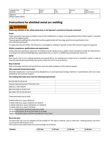
On most digital cameras it is possible to preview the image immediately after it has been taken Use this function and check that the image is sharp in the right place If this is not the case, take another picture If the picturedoes not clearly show what is intended, it is of no use.
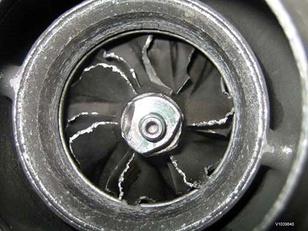
Picture with poor sharpness
NOTE!
If there are any doubts as to what the picture describes, it sometimes may be necessary to add notes or comments to enable those who have to analyse the picture to understand what is intended. It is possible to do this in most picture editing programmes available on the market
Example of how notes or comments can be presented in a picture (it is also OK to insert text boxes, arrows, circles etc. to describe the picture)
1 Example of note/comment
2.Example of note/comment
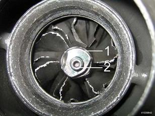 Figure 2
Figure 3
Figure 2
Figure 3
Figure4
Example of general layout picture
If it is not clear which part or component is shown in the picture, it can be illustrated by inserting a general layout picture

NOTE!
This layout should be used when the report applies to attachments, i e buckets etc Insert then a picture of the product identification plate.
How many pictures?
As a rule it can be said that it is the quality of the pictures that determines the value of the pictures not the quantity Try to show what is important with as few pictures as possible It is also not a good idea to enclose several pictures showing the same thing The thinking behind each picture must be to convey important information
GB ART/BHL/CEX/ 900 20 2 06/14/2019
COA/COS/CWL/ EXC/GRD/PAT/ PAW/PIP/RHA/SCR/ SSL/WLO
Applies to Excavators (EXC), Articulated Haulers (ART), Backhoe Loaders (BHL), Compact Excavators(CEX), SoilCompactors (COS), Compact Wheel Loaders (CWL), Asphalt Compactors (COA), Motor Graders (GRD), Tracked Pavers (PAT), Wheeled Pavers (PAW), Pipelayers (PIP), Skid Steer Loaders (SSL), Wheel Loaders (WLO), Screeds (SCR), Rigid Haulers (RHA)
Hydraulic oil leakage from hose, pipe and o-ring
NOTE!
Read and understand the safety instructions in the Operator's Manual and Service Information for the machine.
This Service Bulletin is to be considered as technical information only and is solely applicable for normal warranty in case of failure Proactive replacement parts are not considered to be normal warranty This information is asupplement to existing warranty claim requirements
The analysis of leakage is very important for quality improvement activities In order to analyze the root cause, it is crucial to correctly interpret the claim description of the warranty information system Although the service technician or dealer enters the claim information for the best, some claim descriptions do not have enough claim information to describe what we need to know, the degree of leakage, the location of the leakage and the cause.
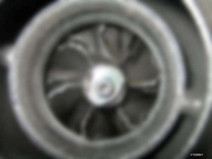
The information about the degree of leakage, the symptom of leakage and the location of leakage should be accurately described in the claim text. Hoses, Pipes and O-rings are judged to be the main components in the external leakage problem and it is required to obtain higher level of leakage information for these parts. It is requested toenter the information about the external leakage as proposed below so that it can be included in the claim description of the warrant system. It is required to attach step-by-step photo, 3-step photos consisting of Leakage Detail photo, Problem Part photo & Sub-System photo
For example:
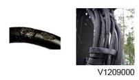
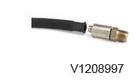
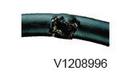
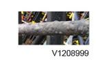
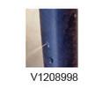
1) Leakage Detail photo (showing where leakage occurs)
2) Problem Part photo (entire hose showing which side of hose is leaked)
3) Sub-System photo (showing where the problem hose is fitted)
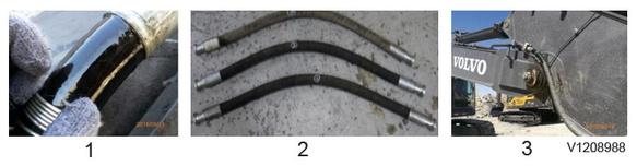
1 Leakage detail
2. Problem part
3 Sub-system
The severity of leakage is the basic information for understanding the characteristic of leakage It is needed to have a common standard to describe the level of leakage The table below provides a uniform guide for defining theseverity of external leakage on hydraulic systems. The description of leakage severity is intended to be by visual means rather than with the aid of instruments. It describes the leakage state at the observed time, considering that the state may change over a period of time. The Leakage description is an excerpt from ISO TR 11340, which is simplified to avoid unnecessary complexity in this standard
Leakage severity
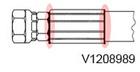
Leakage location of Thread Type hose
Leakage mark
Dripping
Spraying
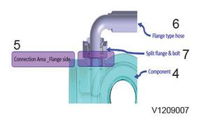
Leakage location of Flange Type hose
Hose leakage can be described by the severity of the leakage, leakage location & leakage symptom. Correct information on these is necessary to identify the problem and to find the correct solution. The more information wehave, the better we understand the exact situation of leakage
For example:
1) Severity of the leakage (showing how much severe leakage occurs)
2) Leakage location (showing which point of the component is problem)
3) Leakage symptom (provides general description of failure mode)
Hose leakages have many kinds of symptom and the below table shows typical symptoms which are frequently observed in the field. Also the scope of the symptom is limited to the symptom when the dealer or service technicianlooks at the machine from the outside, not after the hose assembly is disassembled. Symptoms that happen on the inside of the hose or inside of the fitting and inner rubber are excluded.
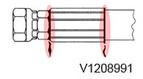
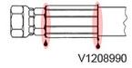
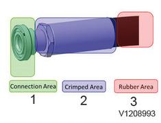
Leakage locations are divided into 3 main areas below, see Table 2 for the details
1) Connection Area
2) Crimped Area
3) Rubber Area
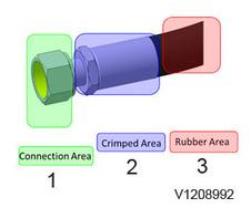
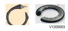
Leakage location of Hose assembly
Leakage location of Thread Type hose
Leakage location of Flange Type hose
The leakage location area together with a description of the type of failure (see Table 3 for typical failure types) shouldbe specified as part of the claim description
4. Hose assembly leakageSymptom of Hose assembly
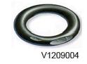
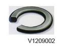
O-ring seals are susceptible to failure. Broken O-ring or Deformed O-ring are top rankers in O-ring leakage claims. While there are number of different types and causes of O-ring failure, this document intends to cover only the types encountered most frequently The table below shows the major symptoms of O-ring failure with example photos and it isthe failure modes which can be identified when defect parts are disassembled

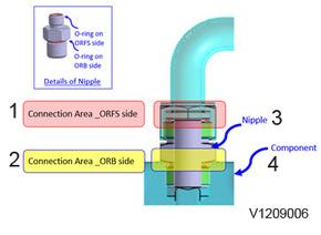
Leakage locations of O-rings can be categorized into two, one is “Leakage from Nipple Type Connection” and another is “Leakage from Flange Type Connection” Nipple Type Connection has two O-ring locations, 1st is O-ring on the ORFS(O-ring Face Seal) side and 2nd is O-ring on the ORB(O-ring Boss) side. Flange Type Connection has one O-ring location, which is on Flange side. The details are in the table below.
An example of the claim description considering the above is “O-ring is Cracked to Drip at ORB side”.
Symptom of O-ring
Deformed (compression set)
Extrusion (nibbling)
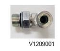
Leakage location of O-ring
Leakage location of Nipple Type Connection
Leakage location of Flange Type Connection
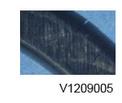
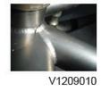
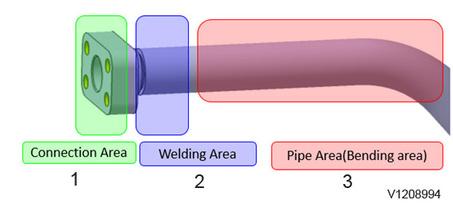
Generally speaking, the main cause of pipe leakage is “crack”, crack at welding area or bending area. The symptoms of pipe failure with example photos is listed in the table below.
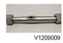
Leakage location of pipe assembly are divided into 3 main areas, see Fig. 2 for the details.
For example:
1) Connection Area
2) Weld Area
3) Pipe Area
An example of the claim description considering the above is “Pipe is Cracked to Spray at Weld Area”
Symptom of Pipe

 Symptom
Figure 2
Example
Cr ack
Brea kage
Deformed
Leakage location of Pipe
Symptom
Figure 2
Example
Cr ack
Brea kage
Deformed
Leakage location of Pipe