Standard Supports 2020

Edition: September 2018
The LISEGA product program covers all components required for the implementation of modern concepts in the support of pipe systems.
These components correspond to the LISEGA standardization philosophy and are organized in a modular system with load and attachment compatibility.
Containing the complete product program, this catalog is in full compliance with LICAD, the LISEGA pipe support design program.
The catalog and LICAD can be downloaded from www.lisega.de.
LISEGA reserves the right to introduce revisions in the interest of further technical development.






Detailed information on contents in the individual sections Product group
Technical specifications
Constant hangers, constant supports
Spring hangers, spring supports
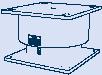
Snubbers, rigid struts, energy absorbers, viscoelastic dampers, dynamic clamps
Pipe clamps, clamp bases, pipe connecting parts

Roller bearings, pipe saddles, cryogenic clamp bases
Threaded connecting elements
Plug-in and Libraries
Structural attachments, trapezes, clamps, slide plates
LISEGA software tools for planning and design
Supplementary services, engineering, field service
0
1
2
3
4
5 6 7 8 9
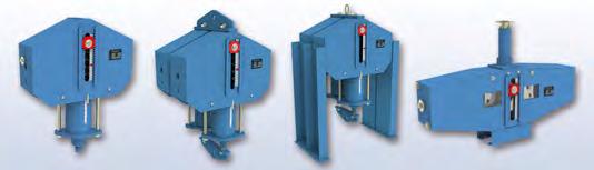
Product group 1
Constant hangers, constant supports, types 11-14, 16-19
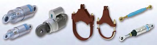
Product group 3
Snubbers, energy absorbers, rigid struts, viscoelastic dampers, dynamic clamps, types 30-39
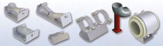
Product group 5
Roller bearings, pipe saddles, cryogenic clamp bases, types 51-58
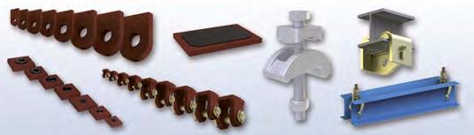
Product group 7
Structural attachments, trapezes, clamps, slide plates, types 73-79

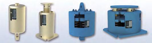
Product group 2
Spring hangers, spring supports, types 20-22, 25-29

Product group 4
Pipe clamps, clamp bases, pipe connecting parts, types 41-46, 48-49
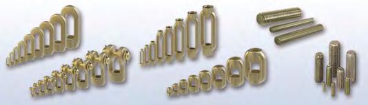
Product group 6
Threaded connecting elements, types 60-67
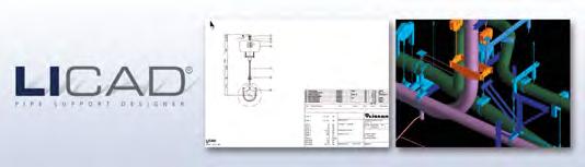
Product group 8
LISEGA software tools for planning and design

Product group 9


Supplementary services, engineering, field service
ProducT 0
2 3 4 5 6 7 8
The products outlined in this catalog – Standard Supports 2020 – are fully in line with the latest developments in support technology and satisfy general requirements for plant installation at the highest level. For the general design of LISEGA standard supports, standardized criteria are applied. They are described in the following Technical specifications and apply to the contents of this catalog. Component related features are outlined in the corresponding sections of the product group sections and in the type data sheets.
Unless expressly agreed otherwise, the stipulations in the catalog Standard Supports 2020 apply to all our shipments.
1.1
For the support of industrial piping systems the use of standard supports is regarded as well-proven, up-to-date technology.
Only a high level of standardization can satisfy the demand for technically superior and economical support components. The complex requirements for modern pipe supports are:
reliable functioning maintenance-free operation quick delivery low component prices computerized design systems easy installation favorable performance weight ratio
1.2 Definition
Standard supports must fulfill the following criteria:
component shapes are uniform and designed to make the optimum use of material components are compatible regarding dimensions and load capacity components are cataloged and clearly designated via an identification system components are manufactured in series production components comply with the approved standards and international codes the functional capacity, suitability and durability of the components is well proven components are certified and approved for use by independent certification bodies
The relevant codes for pipe supports in German and European plant construction (power stations), the DIN EN 13480-T3 and VGB Guideline R 510 L, require the preferential use of standard supports and define the criteria as follows:
“Standard Supports are pipe support components in which the design in form and dimensions, as well as the design data regarding loads, are specified, verified and cataloged and where the components are manufactured according to defined, reproducible processes, e.g. series production”.
2.1
At LISEGA, standard supports form the basis of a comprehensive performance package. A complete product program of more than 12,000 standardized components covers all support situations, operational loads, temperatures and travel ranges normally experienced in piping systems in industrial plant construction:
650°C operating temperature for pipe clamps and clamp bases
400kN nominal load for all mainly statically loaded components
1000kN nominal load for rigid struts and standard snubbers
5000kN design load for large-bore snubbers
900mm travel range for constant hangers
400mm travel range for spring hangers
2.2
Specially developed components are available for the various support functions. Fundamental design principles were taken into consideration in the design and construction of the components:
symmetrical design shapes
compact installation dimensions special, reliable functional principles extra-wide adjustment ranges fully compatible load ranges and connection dimensions integrated installation aids
Moreover, LISEGA hangers feature only one upper connection point. Due to this, along with compact and symmetrical design shapes, load distribution free of imposed moments on the connections is ensured and easy installation made possible. The operating position of the moving parts (hangers, supports and snubbers) can be read directly off a linear travel indicator.
Load adjustment of the constant hangers and supports can be carried out at all times, even in the installed condition. Hangers and supports can be blocked in any travel position.
For the design and arrangement of support components, optimum coverage of the specific support function is the decisive factor. So only one design is required for each function, namely, the optimum one for the purpose. The project engineer is no longer forced to choose from a range of alternative solutions.
This not only facilitates application but also increases safety. In addition it is a prerequisite for the logical implementation of standardized construction according to the modular system.
The cost of pipe supports is a major factor in the total cost of a pipe system. The cost of the supports is the accumulated total arising from the individual costs of:
project management (processing) design and engineering work use of material (components) and installation and assembly work
Moreover, the pipe supports are almost always critical for the commissioning deadlines and can, through delays in delivery, cause incalculable extra costs.
The goal of the LISEGA product strategy is to achieve optimum user benefits for customers at the lowest cost, following the economic principle
The LISEGA modular system provides the corresponding basis. The standardization of components is the decisive prerequisite for:
rational series production favorable performance/weight ratios consistently high product quality ready availability from stock our special LICAD® design software
The cumulative benefits from this result in reliable project processing at competitive prices with superior component quality. In addition, the user also benefits from cost reductions in labor-intensive sectors such as support engineering (design) and onsite installation. The assembly procedure for the pipe systems can also be streamlined by first installing the supports, then mounting the piping directly into them.
The standardization of components at LISEGA is specifically directed toward their systematic interaction as support configurations. To this end, load and travel ranges as well as the geometry of the connections are harmonized. The LISEGA standard support program has been developed in this fashion as a fully functional and effective modular system. The individual components therein form modules and guarantee load compatibility. This enables a wide range of combinations to produce tailor-made support configurations as required. The comprehensive selection of components enables adaptation to widely differing support situations and application conditions.
The standardized components are divided into 7 product groups according to task and function (see standardized components table, page 0.3 and diagram on page 0.4).
To ensure uniform loading in component combinations the product groups are arranged throughout according to clearly classified static and dynamic load groups (see page 0.5 and page 0.6).
The economic principle: = with the least possible effort, achieving the maximum possible benefit = Total Cost Minimum/TCM
First install the supports, then mounting the pipes!
Product groups + load groups + travel ranges + connection compatibility
= Modular System
Modular System + CAD design + IT Logistics System = High-Tech Application
Metric or UNC according to region of application.
For spring hangers and supports (product group 2) the springs are pre-stressed to approx. 1/3 of their nominal load. This results in the initial load.
Within a load group (nominal load), all components feature uniform load limits and safety margins. Within a load group the connection dimensions of the components (thread and pin diameters) are uniform and compatible with the components in other product groups.
As different components can only be combined with each other within the same load group the stresses on a load chain are consistent throughout, whereby the clamps are selected in each case according to the relevant temperature, load and insulation thickness of the pipe system.
The incorrect combination of parts from different load groups is thus avoided.
Moving components such as constant and spring hangers are split into travel ranges corresponding to the usable spring travel of the standard springs used. The relevant travel range in each case is designated in the type designation by the 4th digit in the following table.
&
2 Spring hangers & supports
11 Constant hangers 12-14 Constant hangers, multi-cell
16 Constant supports, multi-cell
17 Servo hangers
18 Constant hangers, low profile
19 Constant supports, low profile
19 Angulating const. supp., low profile
71 Brackets for constant hangers
79 Constant hanger trapezes
20 Angulating spring supports
21 Spring hangers
22 Heavy duty spring hangers
25 Spring hangers, seated
26 Heavy duty spr. hang. (seated)
27 Sway braces
28 Heavy duty spring supports
29 Spring supports
72 Base plates
79 Spring hanger trapezes
30Snubbers
3 Dynamic components
4 Pipe connecting components
5 Pipe bearings and saddle components, cryogenic clamp bases
The LISEGA snubbers are grouped into standard stroke ranges denoted by the 4th digit of the type designation as in the following table.
6 Threaded connecting elements
31 Large bore snubbers
32 Energy absorbers
33 Installation extensions
34 Dynamic pipe clamps
35 Weld-on brackets
36-38 Dynamic pipe clamps
39 Rigid struts
3D Viscoelastic dampers
3L Shear lugs
3R Pipe whip restraints
40 U-bolts
41 Weld-on lugs
42-44 Horizontal clamps
45,46,48 Riser clamps
49 Clamp bases, lift-off restraints
77 Connection plates
51 Cylinder roller bearings
52 Double taper roller bearings
53 Double cylinder roller bearings
54 Weld-on pipe saddles
54 Pipe saddle with pipe clamps
55 Lift-off restraints
56 Cryogenic clamp bases
57 Cryogenic axial stops
57 Weld-on pipe shoes
58 Stanchions
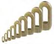
60 Eye nuts
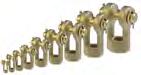
61 Clevises
62 Turnbuckles
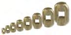
63 Hexagon nuts
64 Rod couplings
65 Tie rods L/R
66 Tie rods
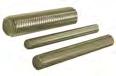
67 Threaded rods / stud bolts
7 Structural attachment elements
70 Sliding components
73 Weld-on clevises
74 Weld-on plates with sph. washers
75 Weld-on eye plates
76 Beam adapters
78 Beam clamps
79 Trapezes
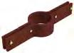






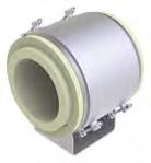
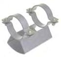

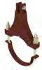
Pipe clamps, clamp bases, pipe connections



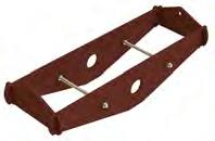
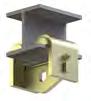
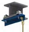
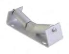
Structural attachments, trapezes, beam adapters, slide plates

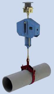



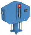
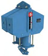
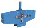
Constant hangers, constant supports


















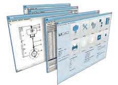
LISEGA Software Tools for Planning and Design



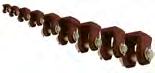
Cryogenics, stanchions, roller bearings, pipe saddles











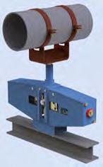








Connecting components




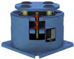
Snubbers, rigid struts, energy absorbers, viscoelastic dampers, dynamic clamps
Load and connection compatibility

























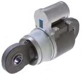

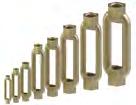



Cold load:
The cold load is the load determined by the pipe system calculations for the support point in shut down condition.
Set load (blocking load):
The set, present or blocking load is the load at which the spring or constant hanger is set and blocked. The set load is made up of the cold load and the dead weight of the components suspended from the spring or constant hanger. In part, blanket dead weights are already calculated into the cold loads. These must be taken into account when designing the hanger arrangement.
Hot load (operating load):
The hot or operating load is the load acting on the support point during normal operation. For spring hangers it is made up of the set load and the force resulting from spring travel multiplied by spring rate. For constant hangers the hot load corresponds to the set load.
Hydrostatic test load:
The hydrostatic test load is the load acting on the support during pressure testing, in general at 80°C.
Pickling (and clean) load:
The pickling load is the load distributed from the support points during pickling of the pipe system, in general at 200°C.
4.1
For permissible loads we distinguish between statically and dynamically loaded components. The components in product groups 1, 2, 4, 5, 6, and 7 are, according to their function, loaded in only one direction (static or quasi static) and are viewed as statically determined components. The units in product group 3 as well as their accessories are regarded as dynamically determined components.
4.1.1
The nominal load is used to denote the load group. For the statically determined components in product groups 1, 2, 6 and 7 the nominal load corresponds to the max. set load of spring elements such as spring hangers. The max. operating load (load case H) is, in the event of use as a rigid support, considerably higher than the nominal load and is adapted to the load capacity of the connection thread. This also includes spring hangers and constant hangers in blocked condition, whereby for cold loads in pressure tests (short duration) the emergency loads (load case HZ) can be exploited.
As these components are generally used as safety devices for emergencies, load case HZ or level C (ASME III / RCC-M) are taken as the maximum occasionally occurring load condition. In any case, the requirements set forth by the responsible project engineer apply.
For product group 4 (pipe connections), a corresponding overlapping area in the load groups is taken into account, due to the wide temperature-dependent range of different loads. Data on the permissible loads for pipe-connecting components under consideration of the respective operating temperatures can be taken from the individual selection tables.
The permissible operating loads for long-term operation (load case H (under normal conditions), normal load, level A) are shown here. On higher short-term loading (e.g. hydrostatic tests) no permanent deformation is caused.
The permissible loads in load cases HZ (emergency (occasionally occurring operating conditions), level C) and HS (faulted condition, level D) depend on the codes to be complied with.
4.1.2
For dynamically loaded components the nominal load corresponds to the operating load for load case H (under normal conditions) or level A/B. (ASME III / RCC-M).
The components in product group 5, clamp bases for cold pipe systems, low temperature systems (cryogenic) as well as roller bearings and pipe saddles, are regarded as static, however they are not considered to be part of the modular system with regard to the load group. As they are more comparable with components in secondary steelwork with respect to loading, they form a separate group. The nominal load here corresponds to the max. operating load according to load case H (normal operation conditions level A/B). For product group 5 see also 4.4.3, page 0.6
For components according to KTA 3205 qualification test the following applies:
4.4 Load tables
The permissible loads of the components are arranged in the form of a matrix (ordered according to load groups and load cases) in the following LISEGA load tables. The definition of the load cases are in line with DIN EN 13480T3, VGB-R 510 L, ASME B31.1, MSS SP-58, ASME
4.4.1
section III, Div. 1, Subsection NF and KTA 3205. The load table applies uniformly to all components in the LISEGA modular system and to other LISEGA components scheduled for use with standard components such as special designs.
4.4.2 Max. permissible loads [kN] for dynamically determined components, product group 3
4.4.3 Max. permissible loads for roller bearings in product group 5
4.4.4 Max. permissible loads for viscouselastic dampers
Max. operating load for spring and constant hanger corresponding to max. load on main springs. The load group allocation does not apply to types 18/19.
Permissible loads according to design criteria for US standard “MSS SP-58” (ASME B 31.1 / B 31.3).
All loads are included here that can possibly occur during conventional operation of the plant, including startup and shutdown, weight tolerances, and hydrostatic tests.
Loads falling outside conventional operation are included here, according to the regulations in each case, also hydrostatic tests. Subsequent inspection of the whole support arrangement is strongly advised.
Due to the loads specified the yield stress of the components can be reached. At all events replacement is recommended.
All dynamic stresses possibly resulting from plant operation are included here including pressure shock forces from valve operations or possibly from operating basis earthquakes (0.B.E.).
All dynamic stresses beyond conventional operation and possibly safety shutdown earthquakes (S.S.E.) are included here. Subsequent inspection of the whole support arrangement is strongly recommended.
For the dynamic loads specified the yield stress of the components can be reached. At all events replacement is strongly recommended.
Load groups 1 and 2 are compatible regarding load and connections, whereby load group 1 refers to the smallest snubber and load group 2 to the corresponding rigid struts and weld-on brackets.
All components can be identified via coded type designations. 6 digits contain all the information required for description of the standard design
The type designation system is the prerequisite for the use of modern IT and enables the unrestricted integration of the LISEGA modular system into current CAD programs.
The LISEGA type designations can be decoded by way of the following tables.
The 1st digit describes the product group (PG)
PG 1 = Constant hangers and supports
PG 2 = Spring hangers and supports
PG 3 = Dynamic components
PG 4 = Pipe connecting components
PG 5 = Pipe bearings and saddle components, cryogenic clamp bases
PG 6 = Threaded connecting elements
PG 7 = Structural attachment elements
The digits 2 – 6 designate the further characteristics according to the following tables. The design for increased requirements (5th or 6th digit) is described on page 0.18.
PG 1 Constant hangers and supports 2nd
2nd digit 3rd digit4th digit 5th digit 6th digit
design load group travel range [mm] field of application production series
8= constant hanger, short D=M10 1=M12 2=M12 3=M16 4=M20 5=M24
9= constant support, short
2= CH 2 x coupled 8 LG10
LG20 3= standard 4= standard with brackets 7= standard <increased requirements> 8= standard with brackets <increased requirements> 5=1985 3= CH 3 x coupled
6= heavy con. support 8 160kN 9 200kN 2=150 3=300 2= coupled 2 x 6=with high temp. SE* 7=with PTFE-SE* 9=without SE*
240kN 9 300kN 3= coupled 3 x 8 320kN 9 400kN 4= coupled 4 x
7= servo hanger 5=M24 6=M30 7=M36 8=M42 9=M48 2=150 3=300 1= standard 5= standard <increased requirements> 5=1985 *SE= sliding element
1,2= standard 5,6= <increased requirements>
1,2= standard constant support
design pipe diameterfield of application production series load group [kN]
T0=1016
6= dynamic pipe clamp with U-bolt Pipe diameter in [mm/10]
T1=1067
T2=1118 T3=1168 T4=1219
9= angulating constant support, short 7=2007
3,4= standard angulating constant support 5,6= support <incr. requirem.> constant support 7,8= <increased requirements> angulating constant support 6=with high temp. SE* 7=with PTFESE*
design load group travel range [mm] field of application production series
1= spring hanger suspendet
0= angulating spring support
0= installation extension for type 20
5= seated
7= sway brace
7= installation extension for type 27
9= spr. support
C=M10
9=installation
f. type 20 & type 27 & type 29
2= standard 6= standard <increased requirements>
1= standard 5= standard <increased requirements> 2= telescopable spring support 6= <increased requirements> 1=1991 4=1994 8=1978 9=1999 1=1991 4=1994 6=with high temp. SE* 7=with PFTE-SE* 8=1978 9=1999
2= heavy spring hanger suspended 6= heavy spring hanger seated 1=LG 10 2=LG 20 3=LG 30 4=LG 40 5=LG 50 1= 50 2=100 3=200
1= standard 5= standard <increased requirements> 2= standard 6= standard <increased requirements> 9=1999
8= heavy spring support 6=with high temp. SE* 7=with PFTE-SE*
digit
design load group travel range [mm] field of application production series
0= hydraulic snubber serial version 2= energy absorber 3= installation extension 1= 3 2= 4 3= 8 4= 18 5= 46 6= 100 7= 200 8= 350 9= 550 0=1000 2=150 3=300 4=400 5=500 8=100 9=200 1= standard 5= standard <increased requirements> 2=2002 3=1993 6=1986 8=1988 at type 32: 6=1996
1= hydraulic snubber large bore 2= 2000 3= 3000 4= 4000 5= 5000 9= 550 0= 1000 8=100 9=200
1= standard 5= standard <increased requirements> 1=1991 3=1993 9=1989
2nd digit3rd +
2nd digit3rd
5= formed riser clamp
6= box clamp for shear lugs
T0= 1016 T1= 1067
T2= 1118 T3= 1168 T4= 1219 1=standard for pipe elbows R 1.5OD max. insulation thickness in
horiz. clamp 2= 1-hole 2= 2-hole 3= 3-hole 4= with U-bolt or strap standard 1=to 350°C 2=to 500°C 3=to 560°C 4=to 600°C 5=to 650°C standard <increased requirements> 6=to 350°C 7=to 500°C 8=to 560°C depending on load group and design riser clamp
8= box clamp for trunnions
PG 4 Pipe clamps, clamp bases and pipe-connecting components (continued)
2nd digit3rd + 4th digit5th digit 6th digit
design pipe diameter [mm] field of application production series
9=
14= 139.7 16= 159.0
17= 168.3 19= 193.7
22= 219.1 24= 244.5
26= 267.0 27= 273.0
32= 323.9 36= 355.6
37= 368.0 41= 406.4
42= 419.0 46= 457.2
51= 508.0 56= 558.8
61= 609.6 66= 660.4
71= 711.2 76= 762.0
81= 812.8 86= 863.6
standard
1=to 350°C
2=to 500°C
3=to 560°C
4=to 600°C
5=to 650°C
standard <increased requirements>
6=to 350°C
7=to 500°C
8=to 560°C
0= U-bolt 1= S235JR 3= 1.4301
91= 914.4 97= 965.2
T0= 1016 T1=1067
T2= 1118 T3=1168
T4= 1219
<incr. requirem.>
6= S235JR
8= 1.4301
1= low
2= medium
3= low, welded
4= medium, welded
5= high, welded
2nd digit3rd + 4th digit5th digit 6th digit
design load group field of application production series
0= eye nut
1= clevis
2= turnbuckle
4= rod coupling
D9= M10-0.62kN
29= M12-2.50kN
39= M16-5.00kN
49= M20-10.0kN
59= M24-20.0kN
69= M30-40.0kN
79= M36-60.0kN
3= hex. nut
89= M42-80.0kN
99= M48-100kN
10= M56x4-160kN
20= M64x4-200kN
30= M68x4-240kN
40= M72x4-300kN
50= M80x4-400kN
5= tie rod L/R
6= tie rod R/R
D=M10
2=M12
8= standard
7= stud bolt, threaded rod
9= lift-off restraint for clamp base 00= lift-off restraint 0= lift-off restraint 1–5= compon. size
2nd digit 3rd + 4th digit 5th digit 6th digit
design load group [kN] field of application production series pipe diameter
1= cyl. roller bearing
2= double taper roller bearing
3= double cyl. roller bearing
5= lift-off restraint for roller bearing
4= pipe saddle with pipe clamps, weldon saddle, pipe tray
6= cryogenic clamp base
7= cryogenic axial stop
04= 4kN
08= 8kN
12= 120kN
16= 16kN
35= 35kN
60= 60kN
01= 21.3mm
02= 26.9mm
03= 33.7mm
05= 48.3mm
06= 60.3mm
07= 73.0mm
08= 76.1mm
09= 88.9mm
10=108.0mm
11=114.3mm
13=133.0mm
14=139.7mm
16=159.0mm
17=168.3mm
19=193.7mm
22=219.1mm
24=244.5mm
26=267.0mm
27=273.0mm
32=323.9mm
36=355.6mm
7= weld-on pipe shoe
8= stanchion
2nd digit 3rd digit 4th digit 5th
1= standard 5= standard <increased requirements>
2=1982 5=1995 8=1978 9=1999
2= standard 3= 25CrMo4 5= standard <increased requirements>
3=1993 8=1978 9=1999
3=M16
4=M20
5=M24
6=M30
7=M36 8=M42 9=M48
10=M56x4
20=M64x4
40=M72x4
Length: 0= LG10LG50
1=stud bolt
2= 500mm
3=1000mm
4=1500mm
5=2000mm
6=2500mm
7=3000mm
30=M68x4 Length not standardized
50=M80x4
1= standard 2= movable laterally 9=1989
1= standard 5= standard <increased requirements>
support bracket for constant hanger
support bracket for heavy constant hanger
2= base plate for spring hanger D…9= load group
Production series/travel/variant Field of application/travel Travel range/pipe Ø/function
Load gr./pipe Ø/thread Ø
Design Product group (PG)
1= weldable 2= with pipe clamps 3= support plate
Length: 3=150mm 5=300mm
7=500mm 8=750mm
Insulation thickness in mm 0= 25
1= 40
2= 50
3= 80
4= 100
5= 130 6= 150 7= 180
8= 200 9= 250
37=368.0mm
41=406.4mm
42=419.0mm
46=457.2mm
51=508.0mm
56=558.8mm
61=609.6mm
66=660.4mm
71=711.2mm
76=762.0mm
81=812.8mm
91=914.4mm
97=965.2mm
1= Standard 1= out of T-section
2= out of U-section
1= rigid pipe supports 2= pipe supports, adjustable
1,2=for str. pipes
3,4=for elbows
R OD
5,6=for pipe elbows
R 1.5 OD
Standard design
Travel range 3 / 0-300mm
Load gr. 5 / FN = 20kN
Individual design
Constant hanger
High design, welded 13CrMo4-5, increased requirements
Pipe diameter 508mm
Clamp base
connection
Standard design Medium length 2500mm
Load group 6 / FN = 100kN
3= weld-on clevis D…50= load group 0 load group 9 1= standard 2= lift-offrestraints 5= standard <increased requirements>
1982 3= 1993 9= 1989 4= weld-on plate
5= weld-on eye plate 6= beam adapter & combinations D…4= size 2= beam adapter & bolts 1= 2001 C…2= size 1= cantilever 6= vertical connection 7= horizontal connection 00=guide 1...4= size 8= beam clamp 2..7= load group 1= standard 1= 1991
9= constant hanger trapeze 3rd to 5th digits correspond to single hangers in each case (see PG1) 3= 2013 5= 1985 7= 2007 9= spring hanger trapeze 3rd to 5th digits correspond to single hangers in each case (see PG2) 1= welded unit 9= with individual hangers
9= rigid trapeze C…4= load group 2,3= depending on design type
0 LG9 3= standard 8= standard <increased requirements> 7= L-section 2…9= load group 9= U-section, centric connection
2…20= load group 4= U-section
7= connecting plate 3rd to 6th digit correspond to the clamps to be coupled
Worldwide coverage of recognized standards
In design, in stress and load calculations, as well as in production, the relevant European and other international standards are taken into account.
The material characteristics upon which all design calculations are based are taken from the relevant standards and technical codes.
the following codes apply:
Standardized selection of carbon steels and heat-resistant materials!
DIN EN 13480-T3
VGB-R 510 L
KTA 3205.1/2/3
AD-Merkblätter
RCC-M
MSS SP-58
ANSI ASME B31.1 / B31.3
ASME section III Div. I - NF
JSME S NC1
JEAG 4601
SPIR-O-2008
Metallic industrial pipe systems Europe
Standard supports Germany
Nuclear regulations Germany
Pressure vessels working group Germany
Specifications for pipe supports France
Pipe supports – material and design USA
Pressure piping systems USA
Supports for nuclear components USA
Nuclear design code Japan
Nuclear design guide Japan
Supports for nuclear plants for AES-2006 Russia
Materials are exclusively used that conform to DIN-EN, ASTM or CN steel material requirements.
Preferred materials for pipe connections
As a matter of course only materials of guaranteed strength characteristics are used for the support components.
High temperature resistant materials for use at higher temperatures or cold tough materials e.g. until – 60°C on request.
All welding is carried out as gas metal arc welding under protective gas according to DIN EN ISO 4063.
MAG/GMAW (= gas metal arc welding), Procedure no. 135
MAG/FCAW (= flux core arc welding), Procedure no. 136
WIG/GTAW (= gas tungsten arc welding), Procedure no. 141
For these procedures (welding procedure specifications (WPS)) are on hand which are certified on the basis of the EN ISO 15614-1 and / or ASME section IX (WPQR).
The welders are qualified according to EN 287-1 and ASME section IX for the corresponding procedures and material classes, and the service personnel for welding equipment according to EN 1418 and ASME section IX.
LISEGA holds certifications according to:
DIN 18800-T7 Kl. E, recertification according to EN1090-1 – EXE 4 conformity certification for support components and EN 1090-2 Technical regulations for the execution of steel construction
ASME section III Div. I Subs. NCA 4000 –NPT and NS stamp
EN ISO 3834-2
TRD 201/AD 2000 Leaflet HPO
Technical Regulations for Steam Boilers/ Manufacture and inspection of pressure vessels by the German TÜV
The current welding inspection team is qualified according to:
EN ISO 14731, welding engineers IWE and EWE (International/European welding engineer) and welding technicians, IWS (International Welding Expert)
Certified welding inspectors according to AWS 1.1
ASME section III Div. I Subs. NF-5500
SNT-TC-1A
Non-destructive testing VT, PT, MT, UT and RT (external) is conducted by test personnel qualified according to standards ISO 9712 Level II and SNT-TC-1A Level II. Supervision is carried out by personnel qualified according to ISO 9712 Level III and SNT-TC-1A Level III.
The tests are conducted on the basis of regulations:
EN ISO 5817 Assessment Group C
EN ISO 17635 (ISO 10836) with relevant stipulations for the various ZfP procedures
RCC-M Subs. H 4000 with MC 3000 – MC 7000
ASME section V as required by subsection NF
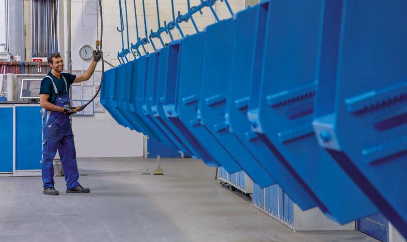
As a matter of principle, LISEGA products are designed for long-term operation, functioning reliably for the whole life of the plant. To limit maintenance work, particular attention is paid to protection against corrosion. It is important to specify the type of surface treatment for the environmental conditions prevailing. LISEGA offers a range of suitable corrosion protection systems based on the corrosivity categories and protection periods of EN ISO 12944:
Standard surface protection (9.1)
Increased surface protection (9.2)
Hot dip galvanized version (9.3)
Surface protection for extreme applications (9.4)
Wherever technically feasible, LISEGA uses low-solvent, environmentally friendly, “water-borne” paint finishes.
9.1
As protection against corrosion, the surfaces of LISEGA products are treated with high-quality protection systems. Our standard corrosion protection corresponds to the Corrosion Category C3, medium protection period (M) according to EN ISO 12944 and is well suited to implementation in environments with a moderate industrial atmosphere. Typical fields of application in this regard are the interiors of production workshops with increased levels of humidity and dust or exteriors with a normal atmosphere.
9.1.1
Data on specified coat thicknesses correspond to NDFT (Nominal Dry Film Thickness) according to DIN EN ISO 12944, measured according to DIN EN ISO 2808.
Metallic surfaces of carbon steel exposed to the open air receive shotblasting to SA 2 1/2 (SP10 according to ASTM) and then a base of zinc-rich primer 60µm is applied. After curing an additional top coating 60µm is applied. The total dry film thickness of the coating amounts to 120µm, color shade RAL 5012 – light blue.
Components falling into this category are constant hangers and supports, heavy spring hangers and supports, trapezes, installation extensions for snubbers etc., rigid strut tubes and viscoelastic dampers.
9.1.2
High quality helical coil springs are an important element in LISEGA constant and spring hangers. Due to their exposed functional significance, all springs are treated with a cathodic electrophoretic dip coating (CED). The springs are shot-blasted and zinc-phosphated on their extended or peeled surfaces. Finally, a dual-component epoxy resin coating is applied in a galvanic process and baked at approx. 200°C.
9.1.3 Electro galvanizing
Spring hangers and spring supports, beam clamps and all threaded components and internal functional parts of the constant hangers and supports are galvanized with a coating thickness of approximately 12 – 15µm.
9.1.4 Hot dip galvanizing
Roller bearings, pipe saddles and cold-block clamp bases are treated as standard with hot dip galvanization, coat thickness 60 – 80µm
9.1.5 Primer coating
Due to their special installation situation, mainly within the insulation, the pipe-surrounding components such as pipe clamps and clamp bases, weld-on brackets, weld-on eye plates, weld-on clevises, weld-on bearings and weld-on pipe supports (stanchions) are treated to higher quality transport protection with a weldable primer coating on a shot-blasted surface, coat thickness approximately 30µm, color shade red brown.
9.1.6 Snubbers
Snubbers are manufactured completely from corrosion resistant materials and require no special coating.
The separate connection lugs of type 30, are manufactured from carbon-steel, and treated according to 9.1.7.
9.1.7 Snubber connections
Connecting lugs are electro galvanized according to 9.1.3 and fitted with corrosion-protected ball bushings. Installation extensions are treated with the standard paint coating according to 9.1.1. Weld-on brackets are given a weldable primer coat according to 9.1.5 and the connection pins are of stainless steel.
9.1.8 Rigid struts
The rigid strut tubes are given a standard color coating (9.1.1). The ball bushing joints are electro galvanized (9.1.3) and fitted with corrosion-protected ball bushings. Weld-on brackets are treated with a weldable primer coating (9.1.5), while the connecting pins are stainless steel.
9.2 Increased corrosion protection
Increased corrosion protection according to EN ISO 12944, Corrosivity Category C4, medium protection period (M), is recommended in aggressive atmospheres, such as in the open in industrial areas and in coastal regions with moderate saline exposure or in the case of internal applications in chemical plants.
Increased corrosion protection is ensured through corresponding additional measures for surface treatment according to 9.2.1 to 9.2.5 on the basis of the standard treatment.
9.2.1 Increased corrosion protection for carbon steel surfaces
Painted surfaces corresponding to the standard version (9.1.1), such as constant hangers and supports, support brackets, trapezes, installation extensions, rigid strut tubes and viscoelastic dampers are topcoated with an additional coat of 60µm on an already existing coat of 120µm, so that a specified coat thickness of 180µm is achieved, color shade RAL 5012 – light blue.
Functional components lying within the constant hanger bodies are also treated according to corrosivity category C4, medium protection (M), in line with EN ISO 12944.
9.2.2 Increased corrosion protection for electro galvanized surfaces
Surfaces electro galvanized as standard according to 9.1.3, such as spring hangers and supports, are given a layer of adhesion primer of 40µm thickness plus a topcoat of 60µm to create a total layer thickness of 115µm, color shade RAL 5012 – light blue.
Threaded parts from product group 6 are not given additional surface coats and can if required be supplied hot dip galvanized.
9.2.3 Increased corrosion protection for spherical bearings
The connecting elements of rigid struts and snubbers receive a special coating containing zinc and aluminum lamellas with an additional organic topcoat, layer thickness approx. 20 – 25µm.
9.2.4 Increased corrosion protection for LISEGA helical coil springs
On top of the standard CED coating according to 9.1.2 a supplementary paint layer with a specified thickness of 60µm is applied.
9.2.5 Increased corrosion protection for pipe clamps and clamp bases, product groups 3 and 4
Pipe clamps and clamp bases for an application range up to 350°C can, if required, be supplied hot dip galvanized.
Pipe clamps and clamp bases for a range over 350°C are given a coating which corresponds in the stability of its maximum working temperature to the following table.
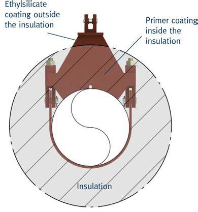
Coating in example of pipe clamps,
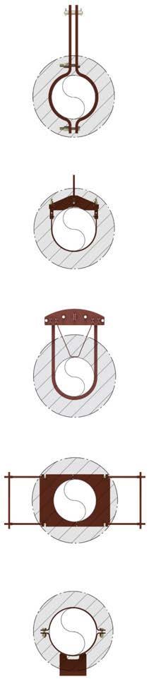
Threaded parts and boltings of the straps, plates, U-bolts and clamps of the pipe-surrounding components must, for increased corrosion protection and a working temperature over 350°C, be located within the insulation in accordance with the installation instructions.
The pin connection of pipe clamps and the end plates of the LISEGA vertical clamps with the adjoining components of the product group 6 must be located outside the insulation.
9.3 Hot dip galvanized version
As an alternative to 9.2, all components in the LISEGA product program can also be supplied as hot dip galvanized version or, where this is not suitable for technical reasons, made from corrosion resistant materials. Components receive a hot dip galvanized coating of approx. 60 – 80µm. Internal functional components, threads, small parts etc. are hot dip galvanized by spin coating and have a thickness of approximately 40µm.
For components not suited to hot dip galvanization due to the material used or the application area, the version ‘Increased corrosion protection C4’ corresponding to 9.2 represents a good alternative.
9.3.1 Constant hangers and supports, product group 1
If required, constant hangers and supports can be supplied hot dip galvanized. When ordering it should be stated whether corrosion protection C3 according to 9.1 is sufficient or C4 according to 9.2 is required. The difference consists in the additional treatment of the inner functional components.
9.3.2 Components in product group 2
Spring hangers and supports are available ex stock in hot dip galvanized versions.
9.3.3 Pipe clamps and clamp bases, product group 3 and 4
See section 9.2.5.
9.3.4 Components in product group 5
Roller bearings, cryogenic clamp bases and pipe saddles are supplied in hot dip galvanized versions as a standard.
9.3.5 Components in product group 6
Connecting rods and other connecting components, tie rods and threaded rods, threaded clevises, threaded eye nuts, turnbuckles and couplings can be supplied ex stock in hot dip galvanized versions.
9.4 Surface protection in extremely aggressive atmosphere
For use in extremely aggressive atmospheres such as e.g. seawater, offshore or aggressive chemical vapors, well-tested corrosion protection systems suitable for all conditions or correspondingly high corrosion resistant materials can be supplied.
10.1.1
Constant hangers and constant supports of the product group 1 are designed, so that in theory, minimum load deviation occurs over the whole operating range. The total deviation arising from springs, bearing friction and production tolerances is restricted to 5% in series production. Load adjustment is made to an accuracy level of 2%.
For spring hangers and spring supports in product group 2 the load changes linearly in line with the spring travel. The deviation of the spring hysteresis from theoretical values, which results from spring hysteresis and production tolerances, amounts to less than 5% within the operational travel.
10.1.3
Snubbers are designed, in the event of an impact load between the component to be secured and the building structure, to produce an instantaneous rigid connection. Slow displacement due to thermal expansion must not be resisted. Hence the locking mechanism that blocks the component reacts to velocity. The individual functional data are specified in section 3, page 3.7.
Viscoelastic dampers are employed to reduce operational vibrations from machines or plant components to a harmless level by means of broadband damping. The kinetic energy is thereby transformed into heat via a viscous mass. The damping resistance in all degrees of freedom is decisive for its effectiveness. The individual functional data are specified in section 3, page 3.13.
Slide plates are used to reduce the lateral forces produced by the change in position of the sliding bearing-points. In the LISEGA slide plates, lowfriction materials are used with self-lubricating characteristics that reduce friction forces by up to 2/3 at an operating temperature of max. 350°C. The individual design data are given in section 7, page 7.10.
FN = nominal load
Fmin = minimum load (upward travel)
Fmax = maximum load (downward travel)
sN = nominal travel (incl. reserve)
FN = nominal load
sN = nominal travel (incl. reserve)
FH = hot load a (operating load) for downward operational travel
FC = cold load a (installation load)
s = operational travel
sa = piston rod tolerance
sb = piston rod travel
sb = operational stroke
Reduction in reaction forces in the piping system by the use of slide plates.
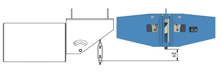
Simple method for checking the installation possibilities with the E dimension!
type 75
type 61
type 66 type 67
When under loading and depending on time and temperature, standard helical compression springs lose a considerable amount of their internal stress through relaxation or settling loss. If no special measures are taken to counter this, in constant and spring hangers, it can in the long-term lead to a reduction of more than 10% in the set ultimate load.
In contrast to common practise, LISEGA exclusively uses specially treated springs that exhibit practically no relaxation.
In these springs the expected settling loss is anticipated through hot setting. This method is called prerelaxation
For the simple determination of the required rod lengths in load chains, the installation dimension E is specified for all components apart from tie rods and threaded rods (product group 6).
This E dimension denotes the respective installation length of the components minus the thread engagement depths (X dimensions) of the connecting tie rods and threaded rods.
type 60
type 42
X = Thread depth
Et = Total installation dimension (Et=Etotal)
= Length adapted to individual installation conditions
The length of the rods required is given by the total installation height (pipe axis to reference edge of connection surface) minus the sum of the E dimensions of the components to be connected.
To determine the total length of the rods in a load chain all the E dimensions are added together. The sum is compared with the total installation dimension. If a difference results which is greater than the sum of the thread engagement depths (X dimensions), then the chain selected is correct for the total installation height.
For load chains solely with pinned connections the minimum installation dimension results from the sum of all E dimensions.
Product-related details are to be found in the selection tables.
Relaxation behavior of helical coil springs
cold set helical coil springs (loosely based on DIN 2089)
LISEGA hot set helical coil springs, qualified by the KTA qualification tests and VGB type tests
product group 1
constant hangers constant supports servohangers
• upper starting position (0 on travel scale)
• on deviation in blocking position to the new blocking position is also to be considered
product group 2
spring hangers spring supports (without type 29 .. 2.)
product group 3
snubbers
• upper starting position (0 on travel scale)
• on deviation in blocking position the blocking position is also to be considered
• upper starting position (0 on travel scale)
• independent of blocking position due to adjustment available in the support tube
• specification of “E min” and “E max” corresponding to possible travel
viscoelastic damper
product group 4
pipe clamps
product group 6
threaded connections
product group 7
structural attachments
• for installation instructions the planned installation position incl. travel reserves is to be taken into account
• middle position
• distance from pipe axis to pin connection or bottom of clamp bases
• middle line of pin or lower edge of thread engagement depth up to upper edge of thread engagement depth
• middle line of pin up to face of structure
11.2.1 Turnbuckle function of connection threads
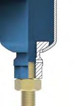
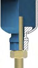
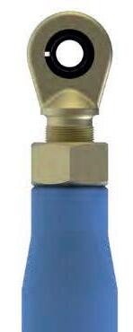
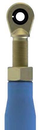
For length adjustment in installed condition (setting pipe installation position, creating force-fitting) the lower connections on the constant and spring hangers are designed to function as turnbuckles. In this way convenient future adjustment of installation lengths (connecting rods) is ensured. The length adjustment amounts to:
300mm for constant hangers type 11 150mm for constant hangers type 18 the adjustment possibilities of a type 62 turnbuckle for spring hangers type 21 min. 140mm for spring hangers type 22 for spring hangers types 25 and 26 the load-bearing rods are led through the weld-on support tube and held by an adjusting nut. Adjustment can be made within the scope of the available thread length of the rods.
All connecting threads are right-hand.
11.2.2 Constant and spring supports
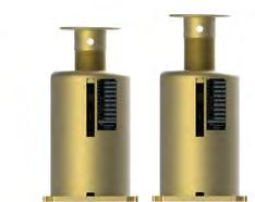
For types 19, 16, 28, and 29, the installation height is adjustable independently of the respective presetting by using the threaded support tube designed as a spindle. The necessary load is reached during installation by the turning of the threaded support tube.
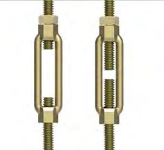
11.2.3 Turnbuckles type 62, tie rods L/R type 65
For rigid hangers with short installation lengths a defined reserved length for connection components types 60 and 61 usually enables sufficient length adjustment. For greater installation lengths the use of a turnbuckle L/R type 62 in combination with a tie rod L/R type 65 is recommended for the purpose of simpler adjustability. For easy accessibility this combination should always be placed at the lowest end of the load chain.
The connections for the rigid struts type 39 are supplied as standard as right/left fine thread for length adjustability in installed condition. Flat faces on the rigid strut body enable easy adjustment with an ordinary wrench.
Further instructions are given in the corresponding installation instructions.
For the effective management and supervision of the organization (Corporate Governance) the Integrated Management System (IMS) summarizes in a centralized structure the established methods and regulations in the company for observation of the demands in the main sectors.
The IMS covers the areas: fundamental company principles quality management environmental protection work and health protection organizational procedures international export certification
Through the utilization of synergies and the pooling of resources, lean and effective management is possible. In IMS the data from the various systems are gathered, analyzed and evaluated centrally according to the requirements of modern CAQ (Computer-aided quality) solutions. The system takes into account recognized standards and guidelines including the corresponding reporting system. Relevant approvals from authorized bodies can be found in the table on page 0.18.
Our quality management (QM) monitors and regulates all activities affecting quality in the company. The independent QM department is the leading system in IMS and has overall supervision of the clearly targeted function of the processes integrated into IMS and the observation of rules and regulations.
One of the most important corporate principles at LISEGA is superior product quality, a vital element which also encompasses the activities and close partnership with our business partners. The organization and behavior of our personnel are correspondingly attuned to this.
The particular measures ensuring quality undertaken by QM are outlined in the quality management program (QMP), which covers the whole organization. These measures and activities to promote quality are an integral component in the processing cycle and are firmly rooted in the procedures.
Constructive devices available for the subsequent adjustment of installation lengths!
The QMP, as an integral component, forms an entity with the processing cycle!
Following international codes and standards, the QMP is described in detail in the Quality Management Manual (QMM). The QMM takes into account all the recognized European and other international standards, especially DIN EN ISO 9001 and ASME section III Div. 1 Subs. NCA 4000 including Subs. NF and KTA 1401, RCC-M H
The QMM covers the whole organization of the LISEGA Group and is applied generally both in the conventional sector as well as in areas with increased requirements, such as the nuclear industry. The scope of the traceability of material, and testing the corresponding documentation can also be adapted exactly to special demands by the activation of further verification levels. All international requirements, including those affecting the nuclear field, can be covered by the QMM. The relevant approvals are available and are regularly renewed.
12.2
All the materials used are monitored by way of a receiving inspection check by quality management regarding compliance with the technical specifications. The materials used are, according to requirements, certified by material test approvals according to ASME and DIN EN 10204.
12.3
The supervision of production is carried out through constant quality control according to QMM. In particular, for nuclear applications the international quality stipulations according to the codes ASME section III NF / NCA 4000 (USA), RCC-M section H (FR), KTA (DE), DIN EN 13480-T5 and NNSA (CN) are fulfilled.
12.4
Before shipment, constant hangers and spring hangers, as well as snubbers and dampers are subjected, under the responsibility of Quality Management, to function tests on special test benches. The measurement and testing is performed with correctly calibrated test and measurement equipment. The measurements are recorded and can if required be accessed and documented. All the testing faculties are regularly inspected and checked by qualified personnel according to EN ISO 7500-1.
If required, the materials used are documented by certification via material tests according to ASME and DIN EN 10204. In addition, the results of the functional test can be confirmed by the issue of an acceptance test certificate, also by an independent test institute if so desired. Computerized verification in line with special requirements and special quality-related documents can be agreed upon between customer, producer and supervisor.
For the use of serially produced standard supports in industrial piping installations, especially in plants with more stringent requirements, e.g. nuclear power stations, special suitability and type tests are required worldwide. The test programs specified mainly involve the following steps:
inspection of the quality management program
inspection of the materials used inspection of the design documentation verification of the computer-based tensile stress values
experimental testing on
• function
• overload capacity
• continuous load capacity
On successful testing, suitability is regarded as proven and general approval can be issued for use in industrial piping installations.
Type and suitability tests have been carried out for the major part of the LISEGA product range by the various German and international, independent institutions. They therefore also comply with the requirements of current European codes.
DIN EN 13480–T3 Section 13
RCC-M H5300, H5400
KTA 3205.3
VGB-R 510 L
Certifications can be supplied upon request.
Our standard supports are absolutely equal in design and function for both the conventional market and where increased requirements are concerned, e.g. in the nuclear field. Hence they do not differ in design or construction. However, due to additional quality assurance requirements and materials with supplementary certification in these sectors, a separate production process may be required.
For areas with increased requirements, all components right up to the finished product must be traceable through batch restamping and the units themselves identifiable according to KTA and ASME codes. In the type designation the
increased requirement level is indicated in the 5th digit and for rigid struts in the 6th digit. The relevant component documentation refers to this and to the number of the production order.
In this catalog the standard component, i.e. the one for conventional applications, is identified by the type designations. As the functional data and component dimensions specified are identical to the increased requirements version, in all cases the selection of products can be made using the catalog. However, when planning or ordering, it is important to verify the part number associated with the requirement level.
The order examples on the individual data sheets should be noted. The type code under Sect. 5 (pages 0.7 and 0.8) can also be used for this.
TÜV Nord BSI
ISO 9001
EN 1090-1:2009/A1:2011
TÜV Rheinland AFAQ LRQA
TÜV Nord
TÜV Nord
Cl. E; DIN 18800-7:2008-11, DIN 18801TÜV Nord
AD 2000 Leaflet-HP0
DIN EN ISO 3834-2
BS OHSAS 18001:2007
„Safety management“
DIN EN ISO 14001:2009
TÜV Nord
TÜV Nord
TÜV Nord AFAQ
„Environmental“ TÜV Nord
SCC
ASME section III Div. I NCA 4000
TÜV Nord
NS - Certificate for supports ASME
ASME section III Div. I NCA 4000
NPT - Stamp for supports ASME
KTA 1401
NNSA Designing
78 100 034445
FS 557331 01 100 038965
1996 / 5030.4
MEA6011026/1 07 100 010963
0045-CPR-1090-1.00151 TÜVNORD.2013.003
DIN 18800-7 / 0513-EW /13/0
07-203-1282-HP-0513/13
07-204-1280-HS-0513/15
78 116 034445 2010/38940.1
78 104 034445
78 106 034445
N 3092 N 3025
N 3169 N 2951
VGB, EnBW Kernkraft, RWE, E.ON, Vattenfall
NNSA Manufacturing China National Nuclear Safety Administration 1405 1406
TN VED / Rostechnazor Federal Service for Ecological, Technological and Atomic Supervision
GOST R RST Expert
SPIR-O-2008
SSMFS 2008:13
ASME section III Div. I, Subs. NF
Separate production processes of components meeting increased requirements for the traceability of certified materials!
POCC DE.A 80.H02052 POCC DE.A 80.H02053 POCC DE.A 80.H02054
ATT=Atomic Techno Test .0001.01 00.00.10.
INSPECTA NUCLEAR AB 5477
Class 1, 2, 3, MC, ASME section XI Tractebel Belgium
At the time of publication. Current certificates can be downloaded from our website.
Piping can only be as good as its supports!
Unless specified otherwise, all products are classified according to component types and shipped in appropriate packaging for transport or for short-term storage. They are clearly marked and, if necessary, protected against corrosion by special measures. If long-term storage is required, different packaging can be agreed on for this purpose.
Specific requirements can, where applicable, be found in the data sheets or installation instructions. Complete pipe supports (load chains of different components) can on request be preassembled, bundled, and labeled.
For all LISEGA components a 2-year warranty is issued from date of commissioning, limited to 3 years after transfer of ownership.
Modifications in the interests of further technical development as well as deviations for technical reasons in the dimensions, loads and weights in the range of the selection tables are expressly reserved. Dimensions are often used as maximum dimensions for clash tests. If required, the exact manufacturing dimensions can be provided.

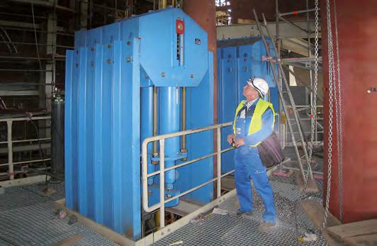
hangers, constant supports
ProducT 1 grouP
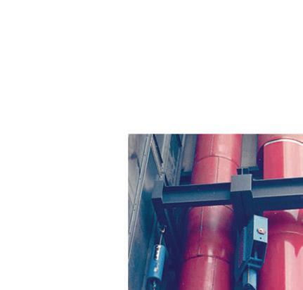
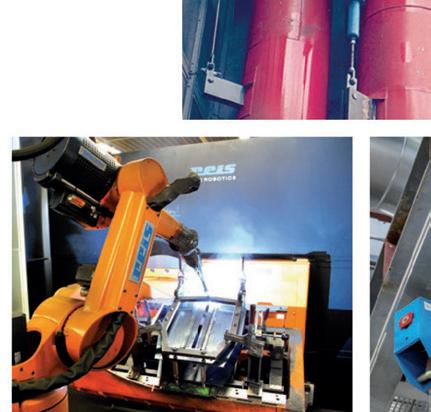
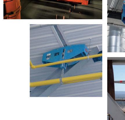
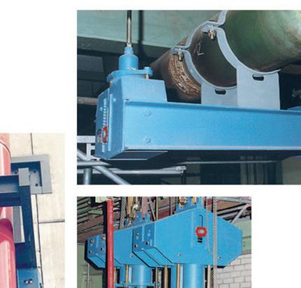
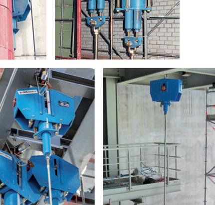
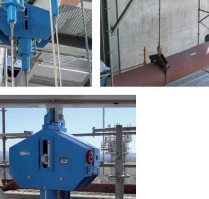


To avoid unacceptable forces and moments in pipe systems, the thermal expansion of the piping must not be restricted.
Minor thermal displacement in the pipe systems in the vertical direction can be compensated by spring supports or spring hangers. Due to the resulting proportionally increasing force deviation corresponding to the spring rate, their use is limited to a displacement range specified by the designer (see product group 2, pp 2.5 and 2.6).
In the case of greater vertical displacement the use of constant hangers or constant supports is required. For these special designs, the spring force is transformed into a constant force throughout the displacement range (see function principle, page 1.5).
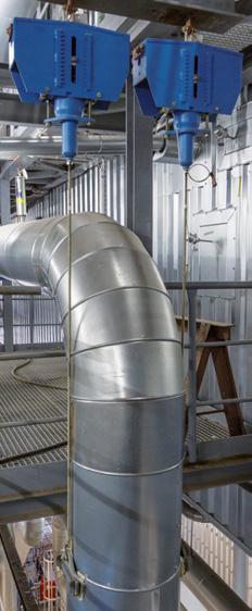
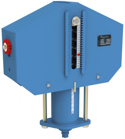
The proportional loads of the pipe system can in this way be constantly distributed over the whole displacement range without significant deviations. As a rule, for LISEGA constant hangers the use of type 11, tried and tested over 100,000 times, provides the standard solution.
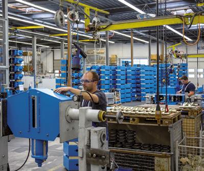
The function principle is based on the arrangement of three springs resulting in the parallelogram of forces. The design is distinguished by highly functional accuracy along with wide load adjustment ranges. The favorable performance-to-weight ratios and symmetrical designs enable easy installation. For further typical advantages, see page 1.3.
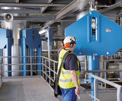
As a rule, the pipe support engineer allows for sufficient installation space for the supports required. However, due to limitations of space the installation height can be too small for the typical standard solution with type 11.

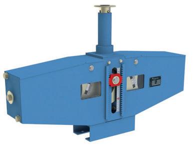
This sometimes occurs, especially when reconstruction existing plants. To provide the optimum solution in such cases, type 18, a low profile design, is available from the LISEGA hanger range, besides the main type 11 series.
The function principle of this design is based on the lever principle. Unlike the usual leverarm type hangers, the load displacement here is linear and is constant, following the LISEGA principle (see function principle, page 1.6).
In the case of constant hangers, the pipe systems are suspended from roof constructions or the steelwork. If the piping is laid out near ground level it may be appropriate to take up the loads from below with constant supports.
Due to its compact design, constant support type 19 thereby replaces its predecessor, type 16, as standard. Type 16 continues to be standard only in the heavy-duty range (load range 100 – 400kN) for its coupling capacity.
On the basis of their special function principles and modes of design, LISEGA constant hangers and supports have, for the past five decades, proven their outstanding operational safety and reliability many thousands of times. Further descriptions of their mode of operation and function are set out on page 1.6 and their design features from page 1.7.
For the operational safety and long life of the pipe systems and hence of the plant itself, the consistent functional accuracy of the constant hangers is of utmost importance.
In comparison with conventional lever-arm type hangers the new LISEGA type 18 is lower profile and enables the creation of support chains in the smallest of spaces.
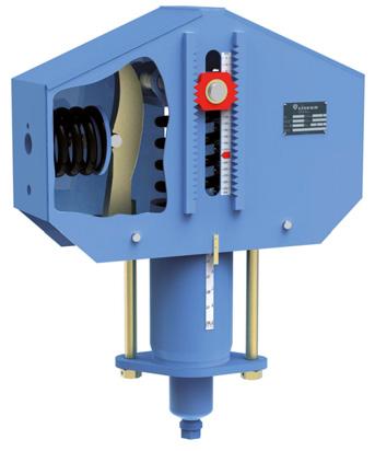
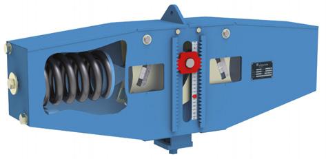
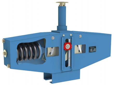
The user can profit from a variety of special benefits where LISEGA constant hangers are concerned.
Significant savings are possible, especially regarding labor-intensive ancillary support costs such as planning, installation and operation.
Principle-based constancy by way of a special function principle.
Pre-relaxed springs eliminate any significant loss of load-bearing capacity.
Reduced friction due to minimized number of bearing points.
Especially wide load adjustment range avoids hanger replacement when operational loads change.
Turnbuckle and swivel joint function allows greater adjustment of pipe installation position.
Load application free of moments due to a single suspension point.
Blocking device through fine rasterization nearly infinitely variable
Name plate contains complete technical specifications
Directly readable travel scale with marking for hot/cold positions.
Load scale with permanent marking of set load.
Symmetrical design ensures direct flow of forces through axis of symmetry.
Favorable performance-weight ratios for reduced installation loads.
Arranged by load groups and travel ranges to simplify selection (modular system).
Consistent functional behavior due to highquality corrosion protection and maintenance-free chemically nickelized finishes.
Readily adaptable to installation situation via corresponding designs and standardized accessories.
Double load-tube guiding of constant supports for transmission of side loads.
Secure connection of load chains due to load- and connection-compatible modular components.
As fixed elements in the pipe system concept, the pipe supports must operate smoothly as functional connections between the pipe system and the surrounding structure.
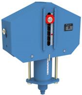
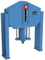
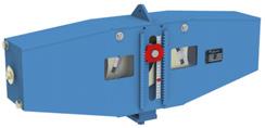
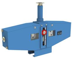
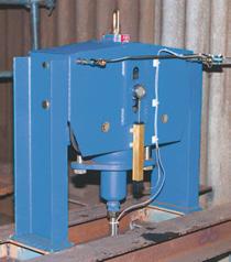
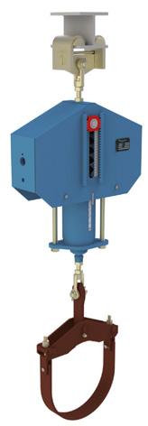
Pipe systems are usually very complex layouts with restricted space. To allow for optimum use of the different spatial conditions, various designs are available as standard for the different application situations. All components are available either from stock or at short notice.
Constant hanger type 11 C3 19 to 11 96 15
Standard design for use as suspension for loads up to load group 9 (100kN) and travel range 6 (750mm). Travel range 7 (900mm) is available on request. If no space restrictions or other specifications are to be considered, this is the preferred product.
Constant hanger type 11 with support brackets type 71 C3 .1 to 71 96 .1
Standard design with support brackets bolted at the LISEGA factory for use as seated versions.
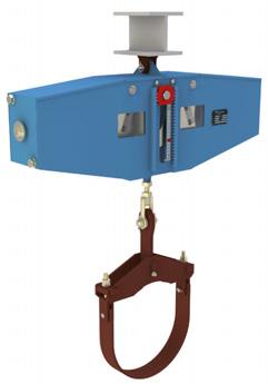
Constant hanger type 18 D3 17 to 18 93 17
Serial standard design in special low profile version as alternative suspension to type 11, if the installation height is limited.
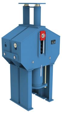
Constant support type 19 D3 17 to 19 93 17
Serial standard design for use as support if constant support from below is required.
Note: This version replaces the taller single-cell constant hanger type 16 (see Standard Supports Catalog 2010) and is especially suitable in restricted spaces. Type 16 can still be supplied if required.
Heavy constant support type 16
Special design as multi-cell constant support type 16, if heavy loads have to be distributed.
Servohanger type 17 52 15 to 17 93 15
Servohangers are equipped with additional active load regulation and can reduce overloading in the piping system to a permissible harmless level.
Besondere Anforderungen
Besondere Anforderungen
Besondere Anforderungen
An die zuverlässige Funktion von Konstanthängern sind strenge Anforderungen zu stellen:
An die zuverlässige Funktion von Konstanthängern sind strenge Anforderungen zu stellen:
An die zuverlässige Funktion von Konstanthängern sind strenge Anforderungen zu stellen:
➜ exakte Konstantheit bei jeder Lasteinstellung
➜ exakte Konstantheit bei jeder Lasteinstellung
➜ minimierte mechanische Reibungskräfte
➜ minimierte mechanische Reibungskräfte
➜ exakte Konstantheit bei jeder Lasteinstellung
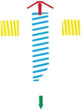
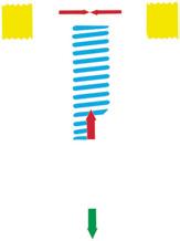
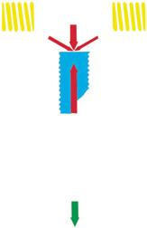
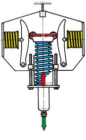
The LISEGA Function Principle is based on the interaction of the force from a mainspring and the resulting force of two connected balance springs. The force directions of the pre-loaded compensating springs are thereby angled against each other in the shape of a parallelogram of forces.
Ebenso sind für die laufende Überwachung des Rohrleitungsverhaltens besondere Voraussetzungen zu erfüllen:
➜ minimierte mechanische Reibungskräfte
Ebenso sind für die laufende Überwachung des Rohrleitungsverhaltens besondere Voraussetzungen zu erfüllen:
Ebenso sind für die laufende Überwachung des Rohrleitungsverhaltens besondere Voraussetzungen zu erfüllen:
➜ zuverlässige Kontrollanzeigen für Einstelllast und Wegstellung
➜ zuverlässige Kontrollanzeigen für Einstelllast und Wegstellung
➜ zuverlässige Kontrollanzeigen für Einstelllast und Wegstellung
➜ ausreichende und präzise Nachstellmöglichkeit der Last
➜ ausreichende und präzise Nachstellmöglichkeit der Last
➜ ausreichende und präzise Nachstellmöglichkeit der Last
Das LISEGA-Funktionsprinzip
Das LISEGA-Funktionsprinzip
Das LISEGA-Funktionsprinzip
The suspended load acts directly on the mainspring via the load tube . The preloaded compensating springs act additionally on the load tube as the resulting force via pivoting cams and roller supports . The mainspring force and the resulting force change on the shifting of the load over the displacement range in accordance with the specified spring constants, the cam path, and the angular position of the cam components.
Für die Erfüllung der Anforderungen bietet das patentierte LISEGA-Funktionsprinzip die besten Voraussetzungen. Hiernach beruht die Wirkungsweise auf dem Zusammenwirken der Kraft aus einer Hauptfeder und der resultierenden Kraft zweier zugeschalteter Ausgleichsfedern. Die Kraftrichtungen der vorgespannten Ausgleichsfedern sind dabei nach Art eines Kräfteparallelogramms winklig gegeneinander gerichtet.
Für die Erfüllung der Anforderungen bietet das patentierte LISEGA-Funktionsprinzip die besten Voraussetzungen. Hiernach beruht die Wirkungsweise auf dem Zusammenwirken der Kraft aus einer Hauptfeder und der resultierenden Kraft zweier zugeschalteter Ausgleichsfedern. Die Kraftrichtungen der vorgespannten Ausgleichsfedern sind dabei nach Art eines Kräfteparallelogramms winklig gegeneinander gerichtet.
Für die Erfüllung der Anforderungen bietet das patentierte LISEGA-Funktionsprinzip die besten Voraussetzungen. Hiernach beruht die Wirkungsweise auf dem Zusammenwirken der Kraft aus einer Hauptfeder und der resultierenden Kraft zweier zugeschalteter Ausgleichsfedern. Die Kraftrichtungen der vorgespannten Ausgleichsfedern sind dabei nach Art eines Kräfteparallelogramms winklig gegeneinander gerichtet.
The course of the resulting force corresponds to the characteristics of the mainspring. In this way the mainspring force is balanced out, without deviations, to a constant support force.
Die anhängende Last wirkt über das Lastrohr direkt auf die Hauptfeder .
Die anhängende Last wirkt über das Lastrohr direkt auf die Hauptfeder .
The LISEGA function principle leads to absolute constancy which by theory can easily be proven.
Die anhängende Last wirkt über das Lastrohr direkt auf die Hauptfeder . Die Vorspannkräfte der Ausgleichsfedern wirken als resultierende Kraft über schwenkbare Kurventeile und die Stützrollen zusätzlich auf das Lastrohr. Die Hauptfederkraft und die Resultierende verändern sich bei Verschiebung der Last über den Bewegungsbereich entsprechend den vorgegebenen Federkonstanten, der Kurvenbahn und der Winkelstellung der Kurventeile.
Die Vorspannkräfte der Ausgleichsfedern wirken als resultierende Kraft über schwenkbare Kurventeile und die Stützrollen zusätzlich auf das Lastrohr. Die Hauptfederkraft und die Resultierende verändern sich bei Verschiebung der Last über den Bewegungsbereich entsprechend den vorgegebenen Federkonstanten, der Kurvenbahn und der Winkelstellung der Kurventeile.
Die Vorspannkräfte der Ausgleichsfedern wirken als resultierende Kraft über schwenkbare Kurventeile und die Stützrollen zusätzlich auf das Lastrohr. Die Hauptfederkraft und die Resultierende verändern sich bei Verschiebung der Last über den Bewegungsbereich entsprechend den vorgegebenen Federkonstanten, der Kurvenbahn und der Winkelstellung der Kurventeile.
The LISEGA function principle permits an especially wide load adjustment range of 40% – 100% of the nominal load.
Der Verlauf der Resultierenden entspricht exakt der Kennlinie der Hauptfeder. Dadurch wird die Kraft der Hauptfeder ohne Abweichungen zu einer konstanten Stützkraft ausgeglichen.
Der Verlauf der Resultierenden entspricht exakt der Kennlinie der Hauptfeder. Dadurch wird die Kraft der Hauptfeder ohne Abweichungen zu einer konstanten Stützkraft ausgeglichen.
Der Verlauf der Resultierenden entspricht exakt der Kennlinie der Hauptfeder. Dadurch wird die Kraft der Hauptfeder ohne Abweichungen zu einer konstanten Stützkraft ausgeglichen.
The load adjustment is carried out by a preloading of the mainspring. As the characteristics of the resulting balancing force and the mainspring are the same, only a linear shifting of the initial force thereby occurs . This way, the change in force is the same at every point of the movement and the ultimate load remains constant at each load setting.
The remaining travel range changes proportionally to the load alterations.
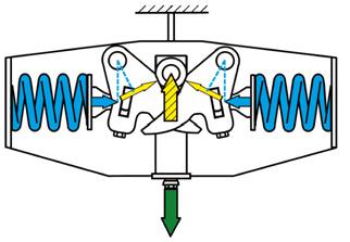
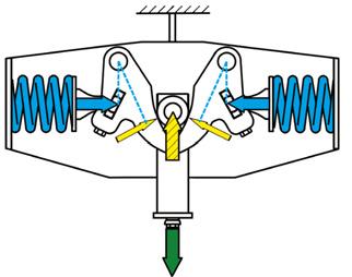
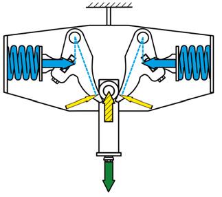
Function principle for LISEGA constant hangers type 18 and constant supports type 19
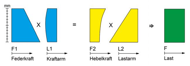
The function principle is based on the lever principle, by which variable spring forces are transformed into a constant support force by way of lever mechanics.
Two lever arms , symmetrically arranged at an angle to each other, thereby act as one system with pre-loaded springs . On a vertical change in position of the load to be taken up, the displacement is distributed over rollers and defined bearing surfaces onto the lever systems. Through the pairing arrangement of the levers the displacement runs linearly in the axis of symmetry, whereby the lever conditions that thereby change do so proportionally to the correspondingly changing spring preloading. In this way the load stays in balance with the set set load in every travel position.
Sinus-shaped load deviations from the lever movement in the form of an arc are balanced by correspondingly machined cam profiles. This way the load distribution is held constant with mathematical accuracy in every position.
The set load is adjustable within a range of approx. 50% to 100% of the maximum hanger force. By way of an adjusting hex-head bolt the length of the lever arm force is continuously variable.
On all load settings the available travel range remains unchanged. The whole working travel range is always available.
LISEGA constant hanger type 11 standard design
A steel body encases the moving parts such as springs and cam lever. The compact arrangement of the individual components enables small external dimensions. The body is designed to bear loads and is mass-produced for the attachment of standardized connections.
The connection threads correspond to the respective LISEGA load group, whereby the upper connection thread (type 11) has a defined thread engagement depth and the lower one is designed as a adjusting nut for length compensation.
Constant hangers and supports are produced as standardized single-cell hangers in load groups C to 9. In addition, type 11 constant hangers in sizes 8 and 9 are coupled to form hangers for higher loads (heavy duty). In this way a standard performance range from 0.13kN to 500kN is covered. Constant hangers are manufactured in the seven standard travel ranges 75 / 150 / 300 / 450 / 600 / 750 / 900 mm and constant supports up to 300mm.
LISEGA constant hanger type 18 compact design
Due to their design, type 11 constant hangers can also be seated directly on suitable supporting components without the need for accessories. In addition, special support brackets can be bolted on using the standard tapped holes provided. Type 11 constant hangers above load group 9 (heavy duty) and type 18 constant hangers are fitted with yoke plates (only on top) for a pined connection, instead of connection threads.
Component design and layout correspond to the applicable national and international standards and recognized technical specifications with regard to load capacity, function and lifespan. This applies equally to the materials used, the welding technology and other processes. The relevant details are clearly defined in the technical specifications, page 0.9.
The springs are crucial components for the smooth functioning of constant hangers and supports – their long-term functional efficiency is vital for the operational safety of hangers and supports. The relevant standards are the basis for the design of LISEGA helical coil springs. Details can be found in the technical specifications, section 0.
When subjected to loads and temperature over a period of time, conventional helical coil springs lose part of their reset force through relaxation (settling loss). In constant and spring hangers this can, in the long term, lead to a reduction in the set ultimate load of more than 10% (see calculation example).
LISEGA exclusively uses springs that, through an artificial aging process, show no appreciable settling loss. The spring relaxation normally to be expected is anticipated by producing preplastification in a hot setting process with greater coil lengths.
The constant hangers are finished with a LISEGA standard coating which, together with a metallically pure treated surface, offers superior corrosion protection with high mechanical stability. Bearings and bearing bolts for the constant hangers are plated or made of nonrusting materials. All threaded components and cams are electro galvanized.
The surface of the spring is given a special finish (technical specifications, page 0.11).
Constant hangers with standard corrosion protection need no maintenance if installed in buildings or in locations protected from the weather. For operation in the open or in special situations, corresponding extra corrosion protection can be arranged – see the corrosion protection section in technical specifications, page 0.10.
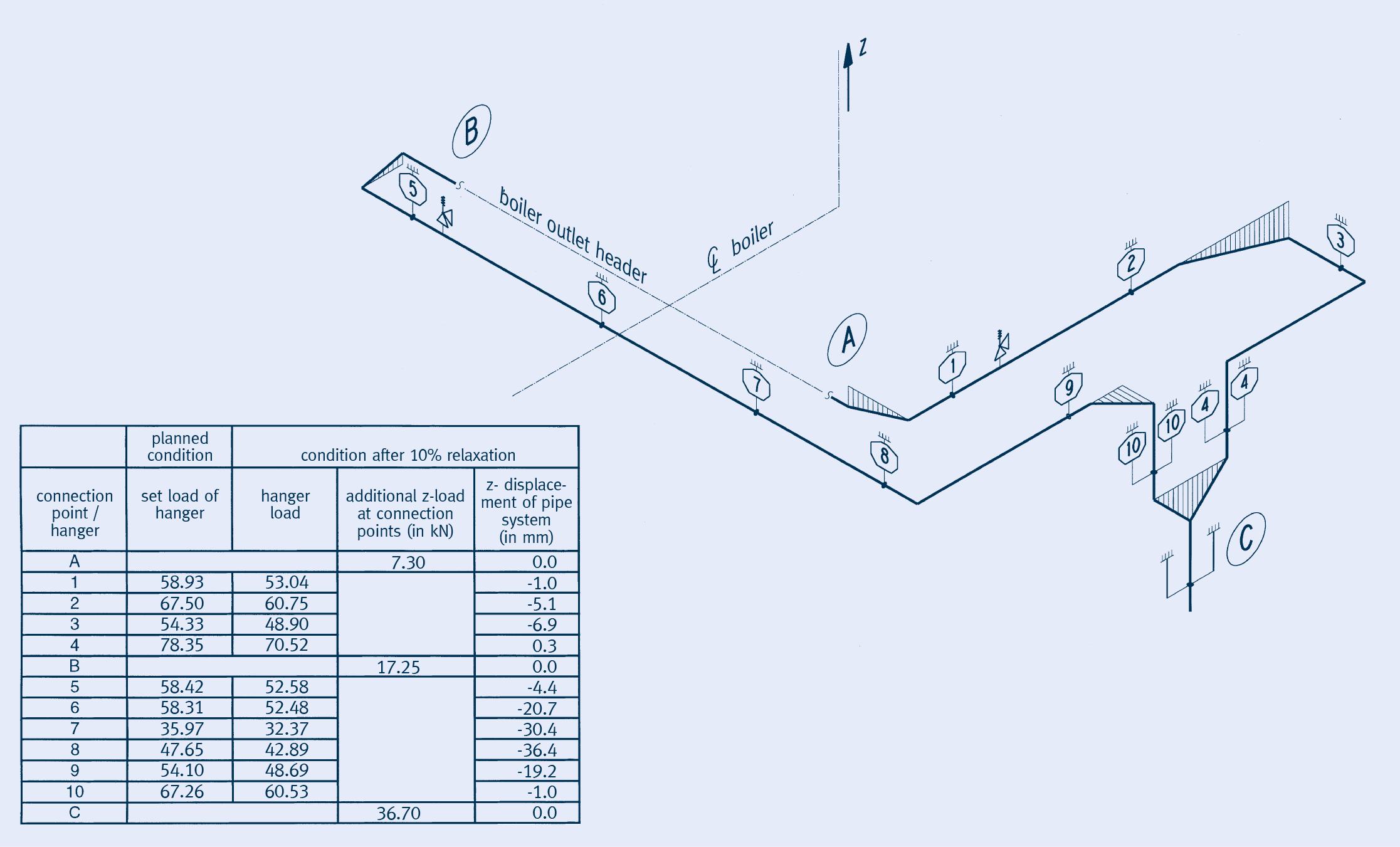
Calculation example of cumulative additional loads due to hanger relaxation A pipe system was observed (dia = 525mm, s = 27mm, temperature = 540°C, pressure = 50 bar). The effect of a 10% loss of force in the hangers was assumed. Due to this loss, the pipe system is displaced by 36.4mm.
The maximum primary stresses were calculated in the vicinity of the boiler connection. They stand 93% above the planned stress condition.
The permissible stresses for the boiler connection are exceeded by 9% (calculations according to Regulation B31.1).
The special functional principle of LISEGA constant hangers guarantees constancy across the entire travel range. This is also unaffected by shifts in load. Only a minor adjustment force produced by tolerances and bearing friction is to be taken into account. The hysteresis so produced is kept within strict limits due to the design principle and modern production processes.
In effect, the deviation in the set load of LISEGA constant hangers on the serial average can, on normal load setting, be kept to 3%.
Applying a selection process, with limited load and travel ranges, it is possible to reduce this even further.
The typical permissible deviations are set out in the following international codes:
MSS SP-58 (USA), max. 6% in relation to the operating load VGB-R510L and KTA 3205.3, Germany, max. 5% in relation to the operating load. The deviation in load adjustment (medium load) is limited to 2%
DIN EN 13480-T3 max. 5% in relation to the operating load
Before shipment, all constant hangers and supports are tested for flawless functioning and set to the load ordered. The test results are recorded.
The calibration values are stamped onto a riveted name plate. The adjusted load is also marked permanently on the load scale. Hot and cold positions are noted on the travel scale in red and white respectively.
The respective travel positions can be read directly off the travel scale in mm or inches.
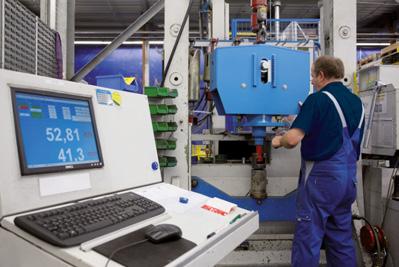
The set load in each case can be read directly off a load scale in kN or lbs. For the functional tests, test benches operating quasi-statically with capacities up to 1,000 kN are on hand. The test benches are checked regularly by an independent supervisory body.

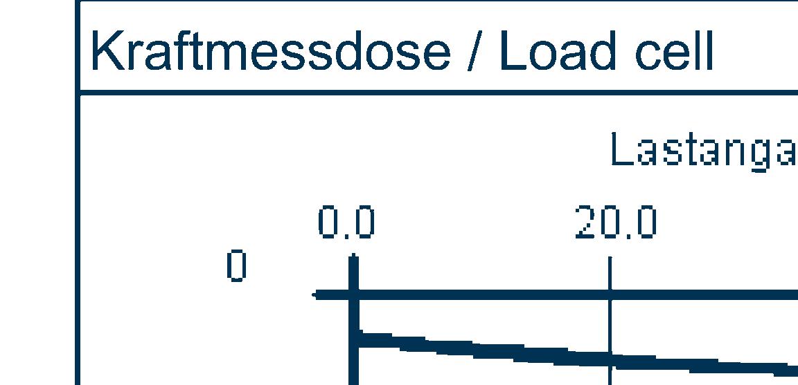
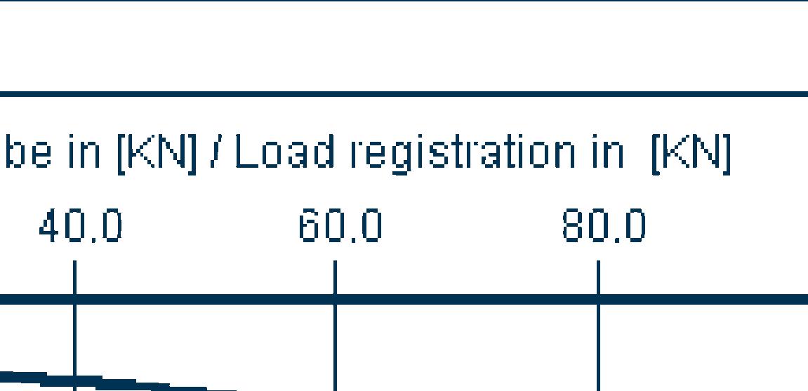
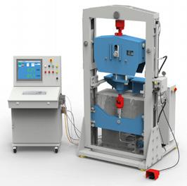
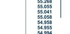
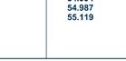
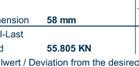
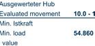
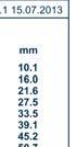
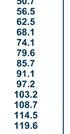
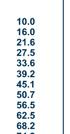
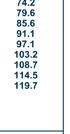

LISEGA testing technology is constantly under improvement and represents state-of-the-art technology. These improvements cover test benches for constant hangers and supports, spring hangers and supports, as well as snubbers.
The testing facilities are in operation at all production sites within the LISEGA group, while mobile units are available for use at customer locations.
32 test benches are on hand for constant and spring hangers or constant and spring supports in the load range from 1kN to 1000kN. All LISEGA test benches are tested at regular intervals according to DIN EN ISO 7500 with calibrated load cells and measurement amplifiers.
All components are tested in installation condition and adjustment.
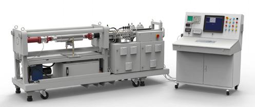
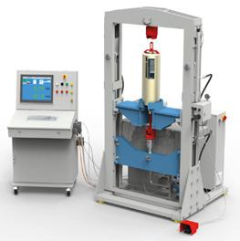
The installation of the constant hangers can be adapted to any situation in the plant through the use of universal accessory components from the modular system.
All configurations can be created in just a few steps via the LICAD design software in the shortest of time with the input of 6 parameters – with parts lists and drawings.
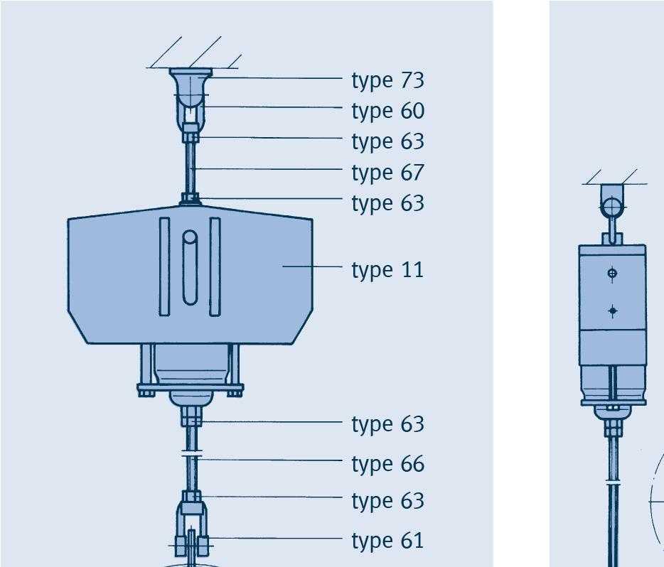
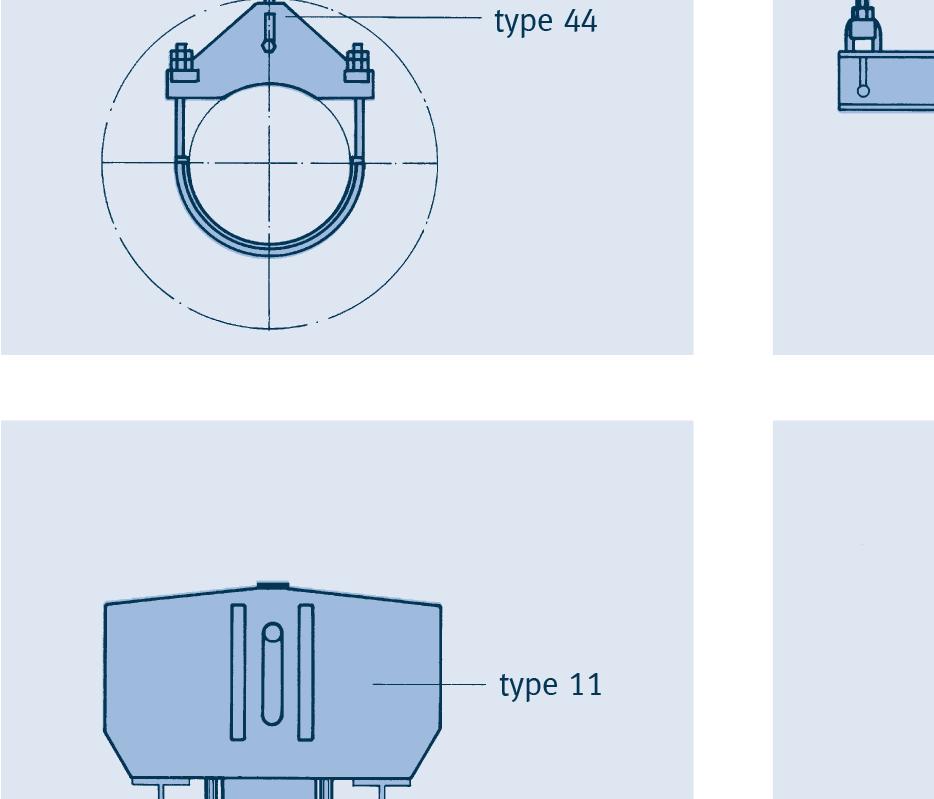
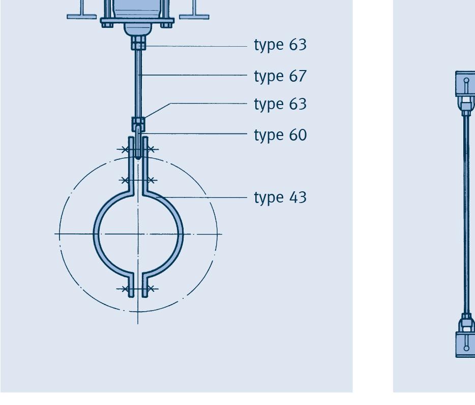
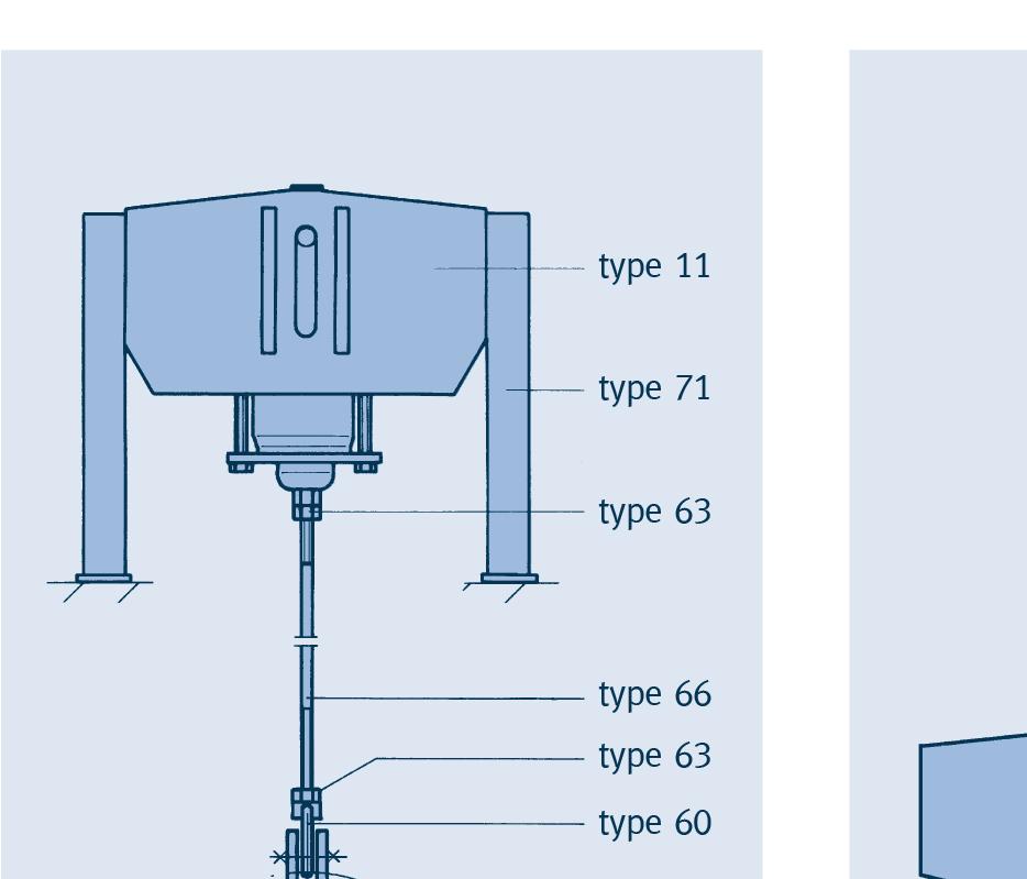
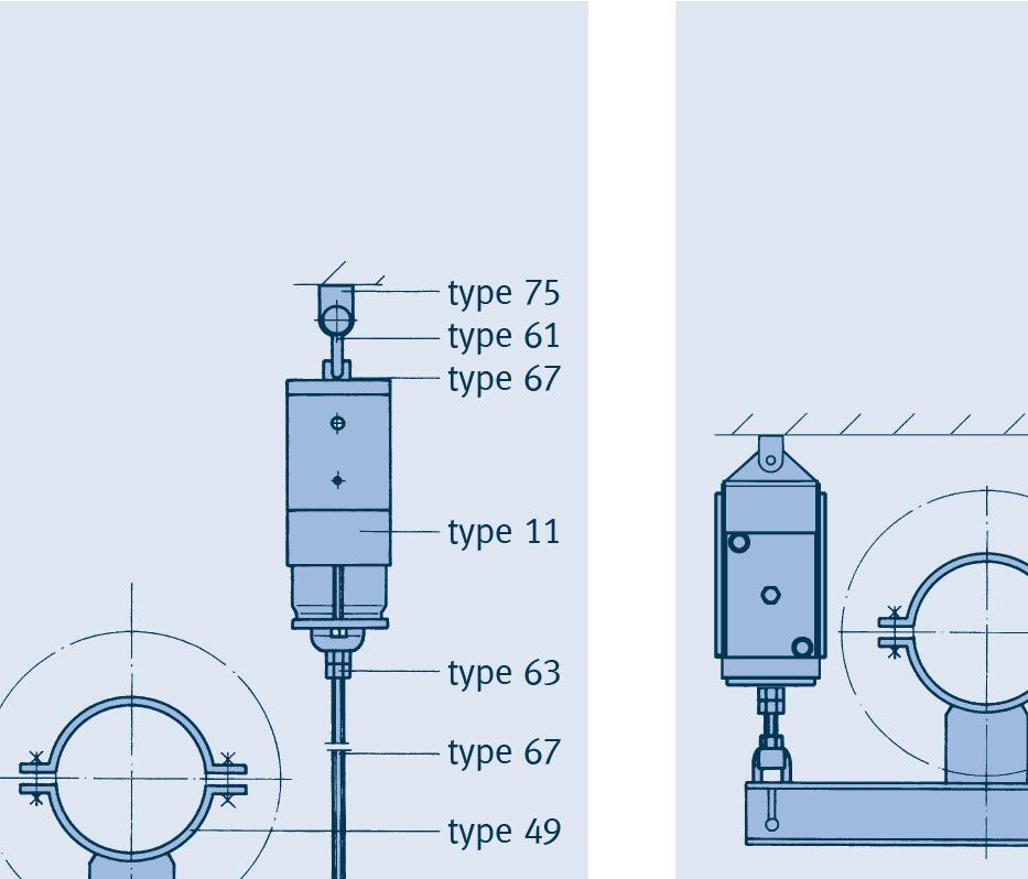
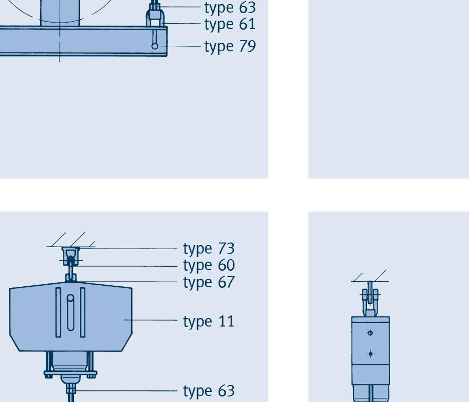
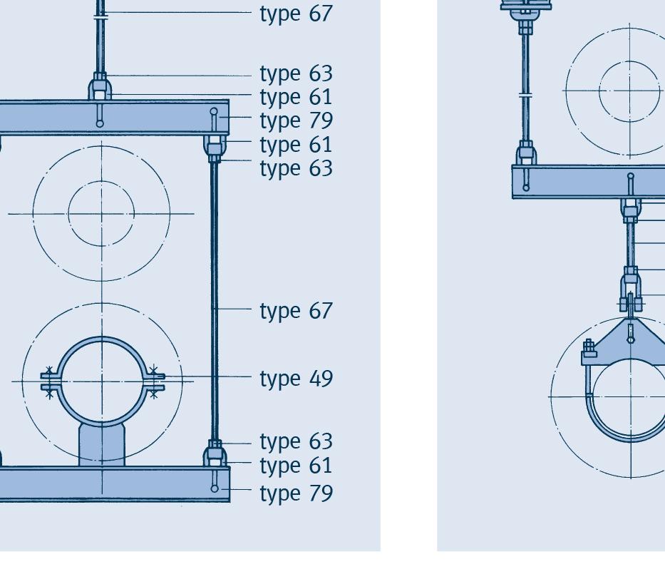
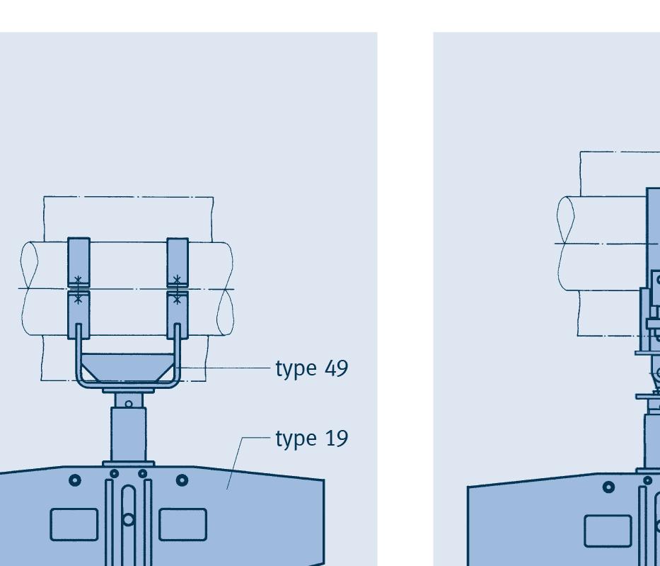
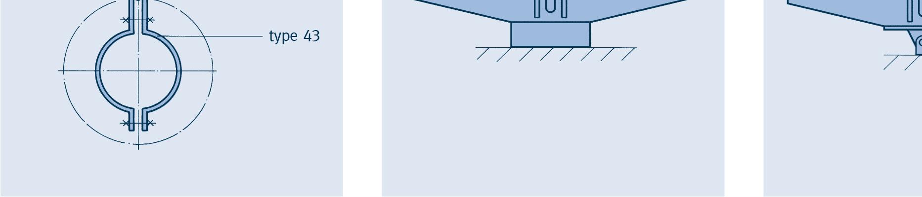

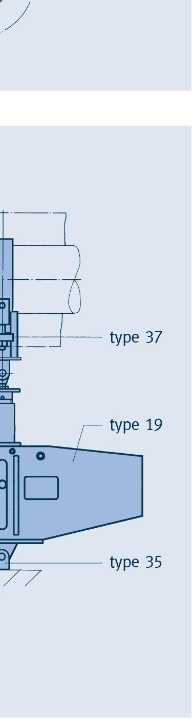
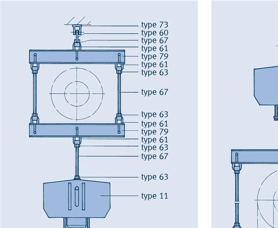
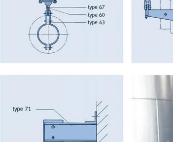
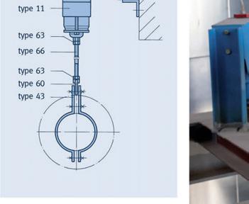
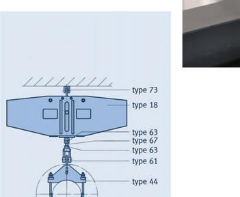
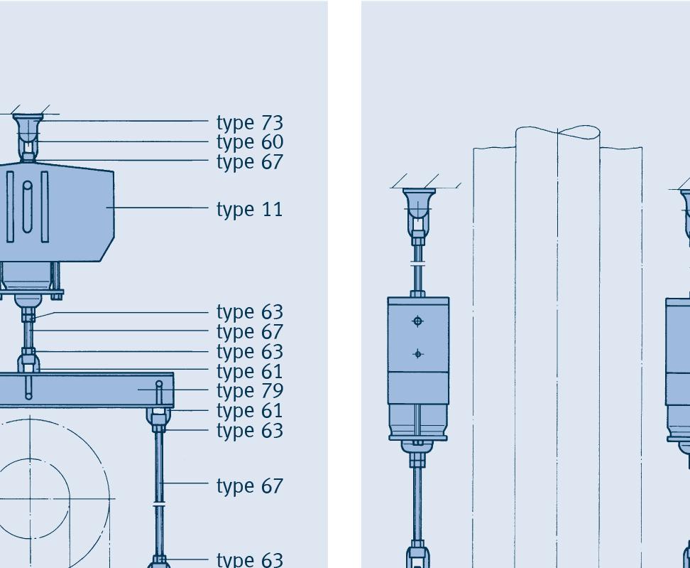
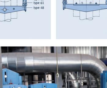
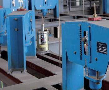
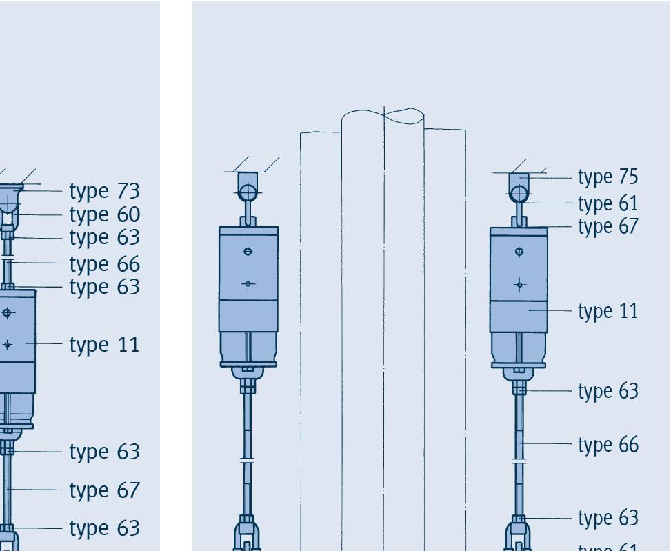
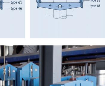
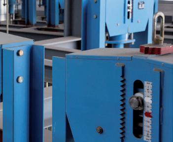

Zwischenwerte können interpoliert werden
For the selection of constant supports and angulating constant supports type 16, the load group and travel range of the corresponding constant hangers type 11 apply.
Loads 0.25kN or 0.13kN on request. This range is only adjustable ex works.
Total travel, travel range 7 (900mm) supplied on request. Selection also applies to heavy duty constant support type 16.
Based on type 11
Constant hangers type 11 C3 19 to 11 96 15 Serialized standard design, delivery from stock.
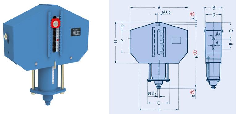
Dimension E for uppermost blocking position, in other blocking positions E lengthens accordingly.
X = minimum thread engagement depth. At the lower connection, maximum thread engagement depth = X + 300mm.
Order details: constant hanger type 11 .. .. marking: … set load: …kN travel: …mm up/down blocking position (as required): …mm
D3 19 410130170106M1011Ø1154544526045280255431519 11 12 15 385130140106M1212M103752652852513540861515 11 13 15 415130140106M1212M1064544528520270165861525
11 14 15 435130140106M1212M1093561528525325225861534
11 15 15 465135150108M1212M10122579529525450350861552
11 22 15 445160180132M1212M103852703502014045861521
11 23 15 460160185132M1212M1065045536045270195861535
11 24 15 480160185132M1212M1094563536045320245861548
11 25 15 530165195136M1212M10121581037025460365861575
11 32 15 445170190132M1612M1039027536010165301122027
11 33 15 490170190132M1612M10675470360702601801102043
11 34 13 545185210150M1612M10960645370403702601102066
11 35 13 615190220155M1612M1012408203704046536011020105
11 42 15 500185220150M2016M12440315400252601351052544
11 43 15 570185220150M2016M127404954101102502101052566
11 44 13 610185220150M2016M121040675410553702751052586
11 45 13 665190240155M2016M1212858554206554045510525145
11 52 15 590230270190M2420M1647034549030210701153073
11 53 15 710230270190M2420M1677051549010528521512630115
11 54 15 745230285190M2420M1611057054907541031012630159
11 55 15 845230285190M2420M1614058804906053041513530212
11 62 15 725275335230M3025M16555420580402408514535134
11 63 15 815275335230M3025M1690056558016030026014535183
11 64 15 845275345230M3025M16128575060015035531014935264
11 65 15 885275345230M3025M16163092560012046038014935337
11 66 15 1145280345232M3025M162030133060015565060014935495
11 72 15 780300380252M3635M206104556505028511017045195
11 73 15 850300380252M3635M2094563565014030020517045262
11 74 15 1000300400252M3635M20137578565019540036017945378
11 75 15 1160305400256M3635M2017109756606566549018445550
11 76 15 1275305400256M3635M202150142566021071067518445690
11 82 15 815320390256M4235M207055856505033011520050263
11 83 15 945320390256M4235M20114071565021534028020050364
11 84 15 1110320400256M4235M20164592567030539042020050509
11 85 15 1200320420256M4235M202085111569012574059520050731
11 86 15 1260325420260M4235M202585162569025085082520050965
11 92 15 865350435276M4835M247606307505035013519560336
11 93 15 1095350435276M4835M24119078575025035532519560475
11 94 15 1240350455276M4835M24173596077038038048019560677
11 95 15 1255355455280M4835M242160109077025058557019560862
11 96 15 1305355455280M4835M2427001620770290800820195601130
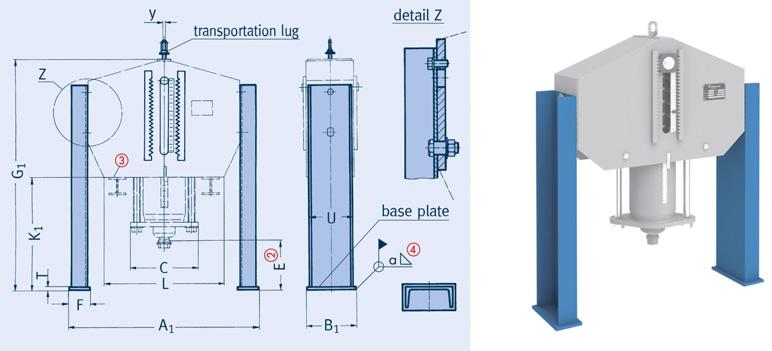
Support brackets for constant hangers type 11 type 71 C3 .1 to 71 96 .1 Serialized standard design, delivery from stock.
Material: base plates of brackets: plate t 15mm : S235JR plate t 20mm : S355J2
The 5th digit in the type designation denotes the design: 6 for support brackets, bolted, standard design, 8 for support brackets, bolted, for increased requirements.
Dimension E for uppermost blocking position, in other positions E changes accordingly.
The constant hangers can in principle be directly seated and welded to the structure. Care must be taken to allow access to adjusting bolts and adjusting nut. If this is not possible, supports type 71 are appropriate.
Minimum weld seam.
Longer support brackets are available on request.
Order details: constant hanger type 11 .. .. with support bracket type 71 .. .. marking: ... set load: …kN travel: …mm up/down blocking position (as required): …mm
Constant hangers type 12 82 35 to 14 96 35 Standard design, multi-cell arrangement, delivery from stock.
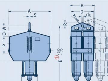

Dimension E for uppermost blocking position, in other blocking positions E changes accordingly.
Order details: constant hanger type 1. .. 35 marking: ... set load: …kN travel: …mm up/down blocking position (as required): …mm

12 82 35 8676353905556012055858054030050330909530160615
12 83 35 99763539055560164071580540300215340909530160820
12 84 35 1162635400555602145925805403003053909095301601110
12 85 35 12526354205556025851115805403001257409095301601555
12 86 35 13126454205656030851625805453042508509095301602020
12 92 35 917695435605701310630905903305035010511035175785
12 93 35 114769543560570174078590590330250355105110351751070
12 94 35 129269545560570228596090590330380380105110351751475
12 95 35 1307705455615702710109090595334250585105110351751845
12 96 35 1357705455615703250162090595334290800105110351752380
13 82 35 867935390855701305585808402x3005033010512535210955
13 83 35 997935390855701740715808402x300215340105125352101265
13 84 35 1162935400855702245925808402x300305390105125352101700
13 85 35 12529354208557026851115808402x300125740105125352102370
13 86 35 13129504208707031851625808502x304250850105125352103070
13 92 35 9171025435935801420630909202x33050350120140352301215
13 93 35 11471025435935801850785909202x330250355120140352301640
13 94 35 12921025455935802395960909202x330380380120140352302245
13 95 35 130710404559508028201090909302x334250585120140352302810
13 96 35 135710404559508033601620909302x334290800120140352303615
14 82 35 867123539011558013855858011403x30050330120180352501305
14 83 35 997123539011558018207158011403x300215340120180352501715
14 84 35 1162123540011558023259258011403x300305390120180352502300
14 85 35 12521235420115580276511158011403x300125740120180352503190
14 86 35 13121250420117080326516258011503x304250850120180352504125
14 92 35 917135543512659014606309012503x33050350135180402501665
14 93 35 1147135543512659018907859012503x330250355135180402502230
14 94 35 1292135545512659024359609012503x330380380135180402503040
14 95 35 13071375455128090286010909012603x334250585135180402503790
14 96 35 13571375455128090340016209012603x334290800135180402504870
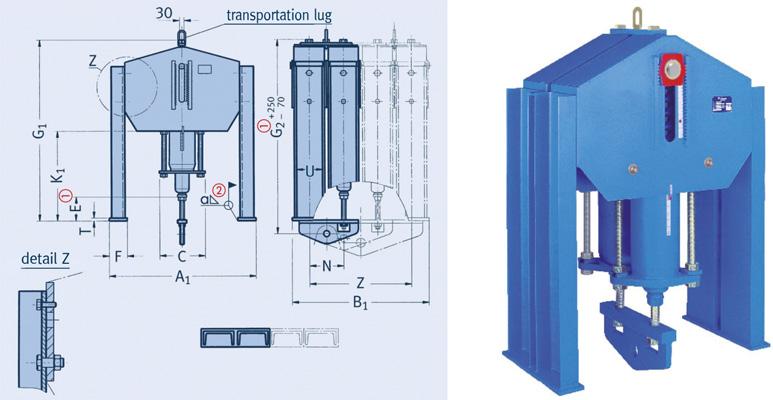
Constant hangers type 12-14 with support brackets type 12 82 45 to 14 96 45 Standard design, delivery from stock.
Material: base plates of brackets: plate t 15mm : S235JR plate t 20mm : S355J2
12
154567545526014030803135140033420320334
11558803903001201550158577530015240600
85 45 141092042054012027302530156030015280600
2044
2848 13 86 45 147092042027012029603030128030415280608
93 45 13359604353101401620168077533020260660
1378
1883 13 94 45 148098045543014022852225126533020280660 5 2647 13 95 45 1495101045555014028302650168033420320668
3551 13 96 45 1545101045526014030803190140033420320668 5 4344 14 82 45 10251180390180120990119035030015240900
2745
Dimensions E and G2 for uppermost blocking position, in other blocking positions E and G2 changes accordingly.
Minimum weld seam. Other lengths are also available on request.
85 45 1410122042054012027302570156030015280900
3817 14 86 45 1470123042027012029603070128030415280912
14 95 45 14951340455550140283026701680334203201002
4766 14 96 45 15451340455260140308032101400334203201002
Order details:
constant hanger with support brackets type 1. .. .. marking: ... set load: …kN travel: …mm up/down blocking position (as required): …mm
Constant hangers type 18 D3 17 to 18 93 17 Standard design, delivery from stock.
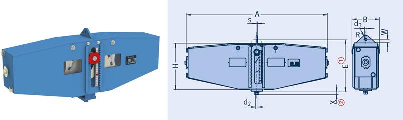
Dimension E for uppermost blocking position, in other blocking positions E lengthens accordingly.
X = minimum thread engagement depth. At lower connection max. thread engagement depth = X + 150mm.
Max. permissible loads:
• Emergency (C) at 80°C = set load x 1.33
• Faulted condition (D) at 150°C = set load x 1.66
• Max. load in a blocked state at 80°C = set load x 1.5.
Order details: constant hanger type 18 .. .. marking: ... set load: …kN travel: …mm up/down blocking position (as required): …mm
18 21 17 1.253.075610205M12172672342510241532
18 22 17 1.253.0150664205M12173042702510241540
18 22 27 2.24.0150664205M12173042702510241540
18 23 27 2.24.0300973205M12174644302510241559
18 31 17 2.85.1575652205M16212822443010362038
18 32 17 2.85.15150837233M16213362933010362076
18 33 17 2.85.153001099233M162148344030103620100
18 31 27 3.86.875652205M16212822443010362038
18 32 27 3.86.8150837233M16213362933010362076
18 33 27 3.86.83001099233M162148344030103620101
18 41 17 5.09.375755233M20213282863010362572
18 42 17 5.09.3150934261M202135130230103625105
18 43 17 5.09.33001099233M202148244030103625107
18 41 27 6.912.475755233M20253312864015322572
18 42 27 6.912.4150934261M202535430240153225117
18 43 27 6.912.43001288261M202550045540153225158
18 51 17 9.216.275755233M24253302864015323073
18 52 17 9.216.2150934261 M242535330240153230118
18 53 17 9.216.23001288261M242549945540153230159
18 51 27 11.921.975812261M24253342904015323099
18 52 27 11.921.91501055276M242537231540153430166
18 53 27 11.921.93001426276M242550846040153430221
18 61 17 16.1529.975878261M303435831550183435119
18 62 17 16.1529.91501140291M303438033350183435201
18 63 17 16.1529.93001592291M303451446750183435273
18 61 27 22.140.575878261M304136831565204435123
18 62 27 22.140.51501302278M304139233565204435205
18 63 27 22.140.53001720302M304152747265204435343
18 71 17 29.847.075976276M364139534065204445164
18 72 17 29.847.01501446291M364139834365204445242
18 73 17 29.847.03001720302M364157847265204445357
18 71 27 35.060.0751072291M364141736265224445201
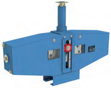
19 12 270.541.7115066424520516314.56002708018510343
19 13 270.541.7130097324520516314.59134308018510366
19 21 171.253.07561024520516314.54902348018510338
19 22 171.253.015066424520516314.56002708018510347
19 23 171.253.030097324520516314.59134308018510366
19 21 272.24.07561024520516314.54902348018510338
19 22 272.24.015066424520516314.56002708018510347
19 23 272.24.030097324520516314.59134308018510367
19 31 172.85.157565224520516314.54992448018510343
19 32 172.85.1515083730023318918.563929310021012485
19 33 172.85.15300109930023318918.5969440100210124112
19 31 273.86.87565224520516314.54992448018510343
19 32 273.86.815083730023318918.563929310021012485
19 33 273.86.8300109930023318918.5969440100210124113
19 41 175.09.37575530023318918.556528610021012480
19 42 175.09.315093430026120518.5667302100210140116
19 43 175.09.3300109930023318918.5969440100210124118
19 41 276.912.47575530023318918.556528610021012480
19 42 276.912.415093430026120518.5667302100210140127
19 43 276.912.4300128830026120518.5987455100210140176
19 51 179.216.27575530023318918.557728610021012484
19 52 179.216.215093430026120518.5668302100210140131
19 53 179.216.2300128830026120518.5987455100210140176
19 51 2711.921.97581230026120518.5581290100210140111
19 52 2711.921.9150105540027622022.5713315120280150183
19 53 2711.921.9300142640027622022.51016460120280150241
19 61 1716.1529.97587830026120518.5607315100210140130
19 62 1716.1529.9150114040029123322.5718333120280163219
19 63 1716.1529.9300159240029123322.51021467120280163294
19 61 2722.140.57587830026120518.5607315100210140134
19 62 2722.140.5150130240027822022.5717335120280150221
19 63 2722.140.5300172040030224022.51041472120280170370
19 71 1729.847.07597640027622022.5655340120280150182
19 72 1729.847.0150144640029123322.5728343120280163263
19 73 1729.847.0300172040030224022.51041472120280170384
19 71 2735.060.075107240029123322.5672362120280163218
19 72 2735.060.0150157040030224022.5757370120280170333
19 73 2735.060.0300193540036230022.51111513120280230565
19 81 1744.280.075125140030224022.5744390120280170303
19 82 1744.280.0150180540036230022.5829413120280230552
19 83 1744.280.0300196540034728522.51186547120280215774
19 91 1759.0100.075152040030224022.5739385120280170352
19 92 1759.0100.0150180540036230022.5829413120280230553
19 93 1759.0100.0300196540034728522.51186547120280215804
Order details: constant support type 19 .. .., marking: …, set load: …kN, travel: …mm up/down, blocking position (as required): …mm The sliding surface of the mating component should be fitted with stainless steel plating. This is indicated by the suffix “SP” in the type designation (e.g., clamp base type 49 22 25-SP).
Constant supports type 19 D3 17 to 19 93 17 Standard design, delivery from stock.
Load plate with integrated slide plate. This must be considered in the selection of clamp bases.
a Dimension E for uppermost blocking position, in other blocking positions E shortens accordingly and allows adjustment of + 60mm
b Type 19 .. .7 is fitted with a load plate with PTFE slide plate as standard. If needed, this type can also be supplied with a high temperature slide plate, type 19 .. .6 (see table below).
c Under certain circumstances the support bracket with the height K can be dispensed with. It should however be ensured that the load adjustment bolts are accessible.
* friction value of the slide plates see table on page 7.11
Max. permissible loads:
•Emergency (C) at 80°C = set load x 1.33
•Faulted condition (D) at
= set load x 1.66.
•Max. load in a blocked state at
=
load x 1.5.
Angulating constant supports type 19 D3 37 to 19 93 37 Standard design, delivery from stock
For large horizontal displacements in the pipe systems the constant supports can be fitted with ball bushing joints.
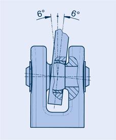
The ball bushing joints for the connection are designed to fit weld-on bracket type 35.
Dimension E for uppermost blocking position, in other blocking positions E shortens accordingly and allows adjustment of +200mm.
Connection possibilities:
See bolt diameter of weld-on brackets type 35 or dynamic clamps (product group 3).
Max. permissible loads:
• Emergency (C) at 80°C = set load x 1.33
• Faulted condition (D) at 150°C = set load x 1.66.
• Max. load in a blocked state at 80°C = set load x 1.5.
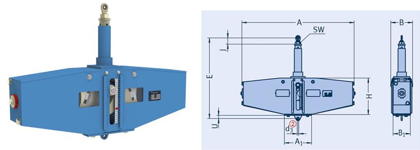
Order details: angulating constant support type 19 .. .. marking: … set load: …kN travel: …mm up/down blocking position (as required): …mm
19 22 37 1.253.01506642452051631260053270342545
19 23 37 1.253.03009732452051631291353430342565
19 21 47 2.24.0756102452051631249053234342537
19 22 47 2.24.01506642452051631260053270342545
19 23 47 2.24.03009732452051631291353430342566
19 31 37 2.85.15756522452051631551259244363042
19 32 37 2.85.151508373002331891563259293363083
19 33 37 2.85.15300109930023318915965594403630110
19 31 47 3.86.8756522452051631551259244363043
19 32 47 3.86.81508373002331891563259293363083
19 33 47 3.86.8300109930023318915965594403630111
19 41 37 5.09.3757553002331891556159286363078
19 42 37 5.09.315093429026120515663593023630114
19 43 37 5.09.3300109930023318915965594403630117
19 41 47 6.912.4757553002331891556159286363079
19 42 47 6.912.415093429026120515663593023630125
19 43 47 6.912.4300128829026120515982594553630175
19 51 37 9.216.2757553002331892060980286604086
19 52 37 9.2 16.215093429026120520700803026040133
19 53 37 9.216.23001288290261205201020804556040178
19 51 47 11.921.97581229026120520613802906040112
19 52 47 11.921.9150105540027622020727803156040184
19 53 47 11.921.93001426400276220201030804606040242
19 61 37 16.1529.97587830026120520641803156040133
19 62 37 16.1529.9150114040029122020732803336040220
19 63 37 16.1529.93001592400291220201035804676040295
19 61 47 22.140.57587830026120520641803156040136
19 62 47 22.140.5150130240027822020731803356040222
19 63 47 22.140.53001720400302220201058804726040372
19 71 37 29.847.07597640027622030708933406060186
19 72 37 29.847.0150144640029123330781933436060267
19 73 37 29.847.03001720380302240301094934726060389
19 71 47 35.060.075107239829123330725933626060222
19 72 47 35.060.0150157040030224030810933706060338
73 47 35.060.03001935400362300301156935136060569
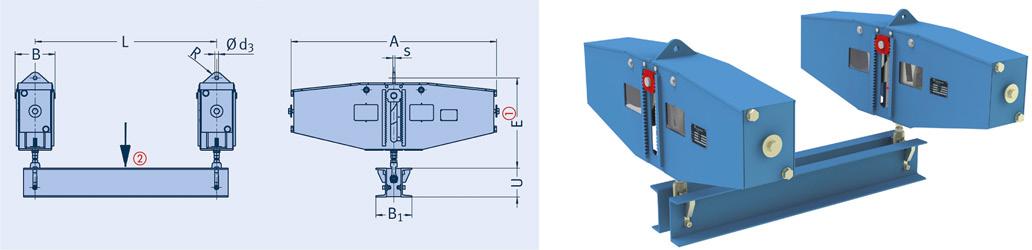
Constant hanger trapezes type 79 D3 17 to 79 93 17
79 D3 17 0.421.02300 1700 973205175692510801401191.7
79 D1 27 0.421.4475 1700 61020517372251080140811.7
79 D2 27 0.421.44150 1700 66420517409251080140891.7
79 D3 27 0.741.44300 1700 973205175692510801401231.7
79 11 27 1.083.4275 1700 61020517393251080140811.7
79 12 27 1.083.42150 1700 66420517430251080140891.7
79 13 27 1.083.42300 1700 973205175902510801401351.7
79 21 17 2.56.075 1700 61020517393251080140791.7
79 22 17 2.56.0150 1700 66420517430251080140951.7
79 23 17 2.56.0300 1700 973205175902510801401351.7
79 21 27 4.48.075 1700 61020517393251080140791.7
79 22 27 4.48.0150 1700 66420517430251080140951.7
79 23 27 4.48.0300 1700 973205175902510801401351.7
79 31 17 5.610.375 1800 6522052141030101201901042.7
79 32 17 5.610.3150 1800 8372332146430101201901802.7
79 33 17 5.610.3300 1800 10992332161130101201902282.7
79 31 27 7.613.675 1800 6522052141030101201901042.7
79 32 27 7.613.6150 1800 8372332146430101201901802.7
79 33 27 7.613.6300 1800 10992332161130101201902302.7
79 41 17 1018.675 1800 7552332147230101402001783.2
79 42 17 1018.6150 1800 9342612148830101402002443.2
79 43 17 1018.6300 1800 10992332162630101402002483.2
79 41 27 13.824.875 1800 7552332547540151402001783.2
79 42 27 13.824.8150 1800 9342612549140151402002683.2
79 43 27 13.824.8300 1800 12882612564440151402003503.2
79 51 17 18.432.475 1800 7552332548940151802301944.4
79 52 17 18.432.4150 1800 9342612551240151802302844.4
79 53 17 18.432.4300 1800 12882612565840151802303664.4
79 51 27 23.843.875 1800 8122612549340151802302464.4
79 52 27 23.843.8150 1800 10552762552140151802303804.4
79 53 27 23.843.8300 1800 14262762566740151802304904.4
79 61 17 32.359.875 2400 8782613452150182603103207.6
79 62 17 32.359.8150 2400 11402913454450182603104827.6
79 63 17 32.359.8300 2400 15922913467850182603106287.6
79 61 27 44.28175 2400 8782614153165202603103287.6
79 62 27 44.281150 2400 13022784155665202603104927.6
79 63 27 44.281300 2400 17203024169065202603107707.6
79 71 17 59.69475 2400 9762764158665203003504309.2
79 72 17 59.694150 2400 14462914158965203003505869.2
79 73 17 59.694300 2400 17203024176965203003508129.2
79 71 27 7012075 2400 10722914160765223003505049.2 79
Dimension E for uppermost blocking position, for other blocking positions E lengthens accordingly.
The Lmax dimensions can be lengthened to 2400mm, on reduction of the permissible center load by 5% per 100mm extension.
When selecting the constant hanger trapeze the weight of the channels and the clamp base weight must be added to the operating load.
Max. permissible loads:
• Emergency (C) at 80°C = set load x 1.33
• Faulted condition (D) at 150°C = set load x 1.66.
• Max. load in a blocked state at 80°C = set load x 1.5.
Order details: trapeze type 79 .. .. L = …mm marking: … set load: …kN of the support point trave: …mm up/down blocking position (as required): …mm
Constant hanger trapezes types 79 D2 15 to 79 96 15 This design of trapeze is used if the standard design type 79 .2 34 does not fit due to extremely restricted installation space. The trapezes are supplied bolted ex works.
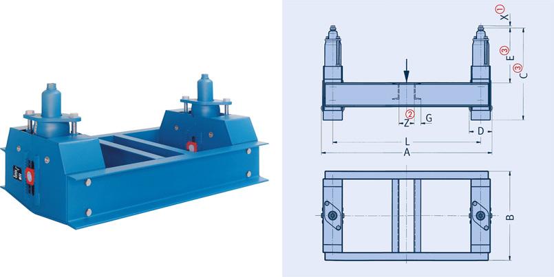
X = min. thread engagement depth + 300mm engagement possibility.
Dimension L and dimension Z are to be stated when ordering.
Dimension E and dimension C at blocking position 0 mm, in other blocking positions E and C lengthens accordingly.
When selecting the constant hanger trapeze its total weight and the clamp base weight must be added to the operating load.
The Lmax dimensions can be lengthened to 2400mm on load reduction by 5% per 100mm extension.
Order details: trapeze type 79 .. ..
L = …mm
Z = …mm marking: … set load: …kN of the support point travel: …mm up/down blocking position (as required): …mm
79 35 13 217077512401907354520002025536.4
79 42 15 21856404651851905520002515344.0
79 43 15 21857107651854155520002519944.0
79 44 13 218575010401856255520002525344.0
79 45 13 219080512851906855520002537044.0
79 52 15 23307405002302756521003023050.6
79 53 15 23308608002304206521003031850.6
79 54 15 233089511352306606521003040850.6
79 55 15 2330100514352308456521003052858.8
79 62 15 23758955902753157021003538466.4
79 63 15 23759859352754807021003548666.4
79 64 15 2375101513202758157021003565066.4
79 65 15 23751055166527510857021003579866.4
79 66 15 2380131520652801265702100351120 66.4
79 72 15 24009706553003208521004554983.6
79 73 15 240010409903005608521004568883.6
79 74 15 2400120014203008208521004594192.4
79 75 15 240513601755305102085210045129692.4
79 76 15 240514752195305127585210045160092.4
79 82 15 2420101575532038095210050746119.0
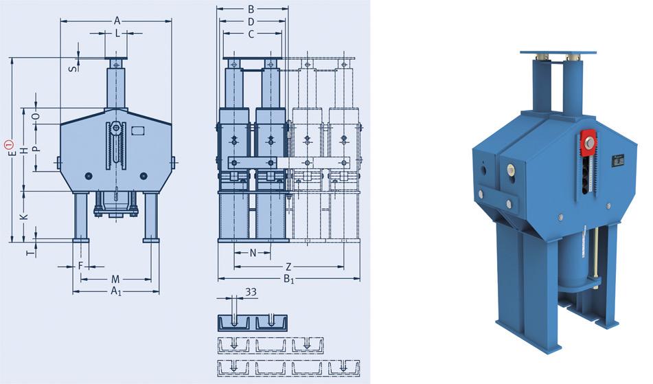
Heavy duty constant support types 16 82 29 to 16 93 49
16 83 29 997640635580500555185518671207157552004903002153401515300920
16 92 29 91774069563057060511901202140630320240570330503502020330805
16 93 29 11477406956305706051915192714078574524057033025035520203301165
16 82 39 86764093588080085511201132120585300200490300503301515600965
16 83 39 9976409358808008551855186712071575520049030021534015156001395
16 92 39 9177401025960900935119012021406303202405703305035020206601220
16 93 39 114774010259609009351915192714078574524057033025035520206601765
16 82 49 8676401235118011001155112011321205853002004903005033015159001295
16 83 49 99764012351180110011551855186712071575520049030021534015159001865
16 92 49 9177401355129012301265119012021406303202405703305035020209901635
Dimension E for uppermost blocking position, in other blocking positions E shortens accordingly and allows adjustment of + 60mm.
Dimension E for constant supports according to E , which are additionally fitted with a slide plate.
Type 16 .. .9 is supplied as standard with a corrosion protected load plate without a slide plate. If lateral movement occurs the use of sliding plates are recommended. Please note the table on the right.
When using slide plates the sliding surfaces of the mating components should be fitted with stainless steel plating.
This is indicated by the suffix ‘SP’ in the type designation (e.g., clamp base type 49 22 25-SP).
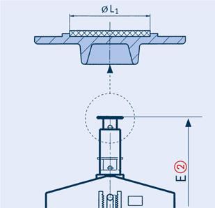
Load plate with integrated slide plate
.716 92 .6150 16 93 .716 93 .6150
Order details: constant support type 16 .. .. marking: … set load: …kN travel: …mm up/down blocking position (as required): …mm * Friction value of the slide plates see table on page 7.11.
Under certain conditions, pipe systems or other components are restricted in their thermal displacement through friction or other influences, despite the use of spring and constant hangers or constant supports. In such cases servohangers can actively overcome the restriction.
In standard cases, the weight of the pipe systems is practically in equilibrium with the set load of the constant hangers and constant supports. The sum of the deviations occurring and the additional stresses in the piping due to this then remain within the permissible harmless range.
In certain cases, the sum of the deviations occurring can also exceed a permissible level and considerably reduce the life of the piping systems or their connections (in the creep strength range) in the form of additional secondary stresses.
Deviations can arise through:
wall thickness tolerances of the piping, if these are not weighed extra and the weight differences taken into account insulation weights not determinable in advance
mechanical friction and production tolerances for constant hangers (permissible +/– 5%) spring relaxation
pipe statics that are not always readily determinable practical deviations from the theoretically planned load distribution
A combination of deviations can cumulatively reach significant levels. These deviations have a particularly negative effect in flexible, ‘soft’ pipe systems. Vertical expansion can be obstructed or even completely suppressed here, even with relatively slight individual deviations.
Apart from the additional loads caused, impermissible sagging can result, due to spring hysteresis in the pressure-stressed system, with a reversed incline. In addition to possible creep rupture, in the event of an incorrectly positioned incline, dangerous water hammer can occur.
In such cases it would be advisable to supplement the passively reacting constant hangers with the active LISEGA servohangers.
without servohangers (diagram on left) the pipe system remains in the hot position
with servohangers (diagram on right) the pipe system shifts to its specified positions
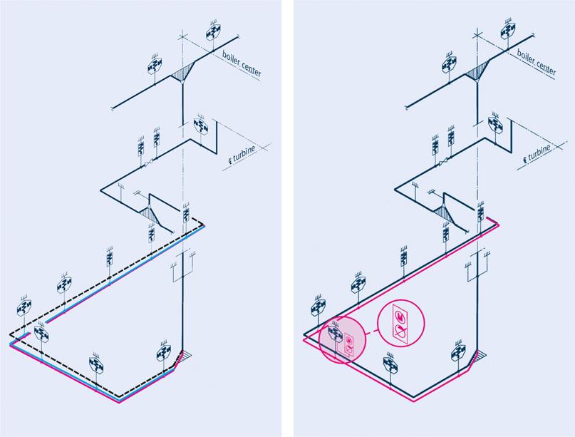
Through use of the hydraulic servo support the pipe system can now be repositioned to the specified elevation.
The type 11 constant hanger forms the basis for the servohanger. To overcome load differences it is additionally fitted with an auxiliary hydraulic device that can exert an active
For theoretical (temp.) / actual (travel) deviations a tolerance range can be set. If the deviation is outside these values, the control switches off automatically.
For any maintenance work required on the system or the boiler, the servo support can be switched on or off manually.
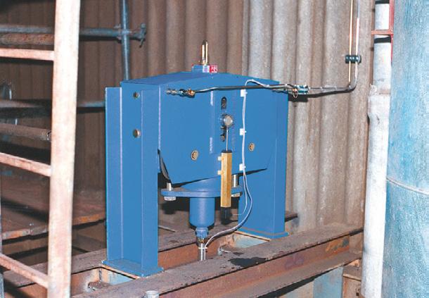
In standard cases, the temperature of the pipe system to be supported is used as a control parameter. The temperature in each case is transformed electronically into the corresponding travel position. In the theoretical / actual comparison procedure, the control ensures a regulated approach to the actual vertical elevation position.
The hydraulic unit and the control are located separately from each other in a separate switch cabinet situated near the servohanger (max. distance 16m).
The hydraulic pistons for control of the movement are located in the load tube of the constant hanger.
The electro hydraulic control is designed so that in the event of an operational breakdown (e.g. power loss) only the servo support is lost, but the unit will continue to function effectively as a constant hanger.
Load Groups 5 (FN 20kN) to 9 (FN 100kN) with travel ranges 2 (150mm) and 3 (300mm) are considered standard. For other cases, special designs can be supplied.
Installation and commissioning instructions, as well as servicing recommendations, are included in the scope of supply.
For this, see also selection table constant hangers, pages 1.13 and 1.14.
2 = travel range 2
3 = travel range 3
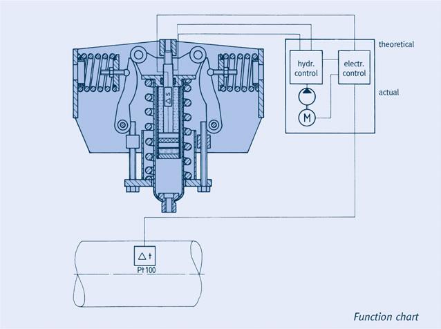
blocking device guide pin
name plate
red marking for hot position retaining bolt with washer for blocking device (after deblocking) travel scale
blocking strip indicator for set load load scale
load adjustment hood load adjustment bolt
load tube
inspection hole for min. thread engagement depth adjusting nut (with swivel joint)
During transport, care must be taken that connecting threads, blocking devices and load adjustment bolts are not damaged. When storing in the open air, the supports must be protected from dirt and water.
If not otherwise agreed, LISEGA constant hangers are set to the desired cold load position
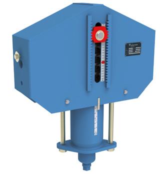
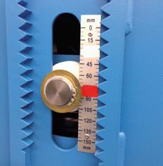
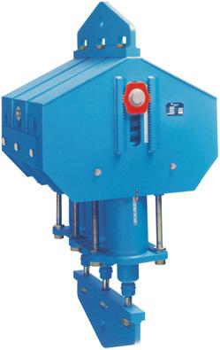
(installation condition) and blocked. The adjustment values can be read off the load and travel scale as well as the name plate.
On the travel scale the theoretical hot position is marked with a red sticker and the theoretical cold position with a white one. At the delivery inspection the customer specified load set at the factory is permanently marked on the load scale with an “X”. The reading is made at the level of the guide pin center.
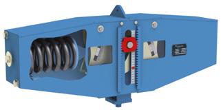
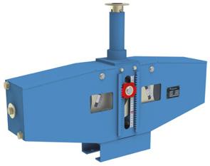
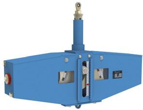
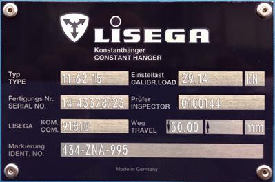
Name plate with stamped operating data
Stamped on the plate are: type serial number
LISEGA order number calibration load (set load) inspector travel
ident. number type
The upper connection is designed as an inner thread with limited engagement depth. The lower connection is designed as a spherical adjusting nut pivotable in all directions by min. 4°. The connection threads are greased and sealed with plastic caps.
When connecting to the connecting rods, care must be taken that the lower rod is screwed into the adjusting nut at least to the inspection hole. A further thread engagement depth of at least 300mm is available.
The upper connection is designed as a yoke plate. The lower connection is also designed as a yoke plate and fastened to the spherical adjusting nuts of the individual constant hanger cells, whereby pivoting of min. 4° is possible.
These constant hangers for all load sizes can be directly seated. They can also be supplied with serial support brackets type 71 which, depending on the order specifications, can be connected and bolted via precision-fit boreholes at works
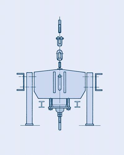
type
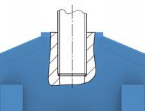
or on site. The base plates of the support brackets can be welded to the contact surface. On request, support brackets with slot holes for bolting can be supplied.
The upper connection is designed as a yoke plate and the lower one as a spherical adjusting nut, pivotable in all directions by min. 4°. The connection threads are greased and sealed with plastic caps.
The upper connections of the constant supports are fitted either with a load plate or slide plate to reduce friction from lateral displacement, or with a ball-joint lug for angulating constant supports. The lower connections are therefore either a pedestal or a lug. During welding work at the pedestal the components inside constant supports must be protected.
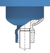
during plant
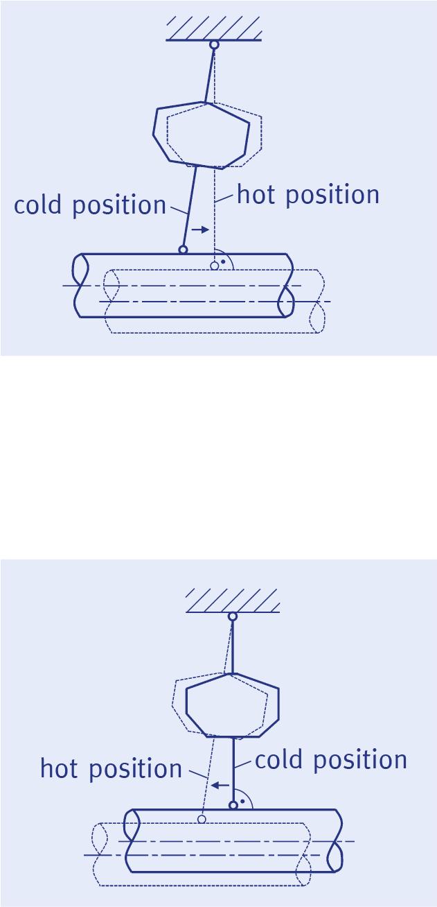
Coupled constant hangers are supplied with a transport locking device (marked in red) consisting of a retaining rod, washer and retaining nut.
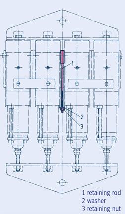
Transport lock type 12 82 .. – 14 96 ..
The transport lock is loosened only on completion of hanger installation and at the same time as the removal of the blocking devices.
For this, the retaining nut with washer marked in red are removed at the lower end with a socket wrench. Both parts are to be stored in the same place as the blocking devices. When making the force-fit connection, care must be taken that the lower threaded rods are screwed into the adjusting nuts at least up to the inspection hole. The installation dimension of the lower yoke plate can be lengthened with the adjusting nuts by 250mm or shortened by 70mm.
When installing, the specifications of the installation instructions for pipe systems must be followed. Special attention must thereby be paid to the desired installation position of the suspension rods throughout the whole support chain. There are two possibilities here:
A) The connecting rods are to be installed at an angle according to the expected horizontal displacement in the pipe system. A perpendicular position is hereby anticipated in operating condition.
B) The connecting rods are to be installed vertically for the purpose of better inspection. A controlled angled position in operating condition is thereby permitted.
In all events, uniform specifications for the whole installation should exist.
The connecting rods and points are to be coupled force-locked.
For installation of the constant hangers, transport lugs or other assembly devices can be screwed into the threaded holes on the sides. After deblocking of the hanger (see point 4) the blocking devices are to be screwed on here for safe keeping. For constant hangers with support brackets type 71 the hangers are fitted with transport lugs instead of the upper connection – these can also store the blocking devices.
For installation of the hangers, the side openings of the upper yoke plate can be used for hooking on. For hangers with support brackets, the upper yoke plate is replaced by a transport lug.
The correct deblocking of the constant hangers in accordance with the following instructions is crucial for the subsequent faultless functioning of the pipe systems.
As far as possible, the blocking devices are to be removed, immediately / shortly before commissioning.
The blocking devices must be removed as a matter of principle in a systematic way, one after the other, beginning at a fixed point or connection point.
The whole system should be inspected beforehand according to point 3 of these installation instructions.
When it has been ensured that all connections are firmly force-locked, the suspended weight is completely taken up by the constant hangers or supports.
If the weight load corresponds to the set load and the piping system shows no sign of stress, then the planned equilibrium has been achieved. The blocking devices can be easily removed.
In practice however, slight stresses in the piping systems and hence resulting load shifting can hardly be avoided.
In the same way, the loads, which are usually determined theoretically, can show larger tolerances. As a result, the deviations can lead (according to under- or over-load) to corresponding jamming of the guide pin in the lower or upper section of the blocking device.
The blocking devices can only be removed when the guide pin is centered in them. The set load is made up of the cold load and the extra weight of the hanger components suspended. If the guide pin is lying at the top or the bottom, the load adjustment must be adapted before deblocking (see point 5, load correction):
When removing the blocking devices, care must be taken that only the outer locking ring is loosened.
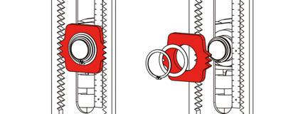
condition Dismantling of the outer locking ring and blocking device
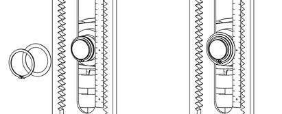
In cases of requirement, e.g. for revisions, the hangers or supports can be blocked again in any position. For this, the blocking devices are placed on the guide pin and secured. The blocking devices should be firmly bolted to the side of the constant hanger body in types 11 to 14, when they are not in use.
Under no circumstances should the blocking devices be removed by force!
By loosening or tightening the connecting rods with a few turns of the adjusting nut in the case of constant hangers, or corresponding adjustment of the support tube for constant supports, stresses in the pipe system can be compensated for and the guide pin is then free.
The geometrical position of the pipe system must not be altered when balancing stresses!
As later adjustment at one point can cause a renewed slight shift at another, the procedure must be repeated if necessary at different points. For clear control it is recommended that, as a matter of principle, the blocking devices should only be removed when all the guide pins are centered in them.
Load correction is necessary if the set load (set at the LISEGA facility) deviates from the weight actually applied. In this case, with LISEGA hangers the set load can also be adjusted in the installed condition.
It should thereby be taken into account that for load increases the remaining travel is shorter. In most cases this is not critical, due to the travel and load reserves available. For safety reasons this should be checked with the catalog data. Any changes in the installation dimension caused by load corrections must be compensated for within the load chain.
Procedure:
1) Loosen both of the load adjustment locknuts.
a) Guide pin is free: Set load of the constant hangers agrees with the weight applied. Blocking device can be removed.
b) Guide pin lies at bottom: Set load of constant hanger is smaller than weight applied. Loosen connecting rod or increase set load.
c) Guide pin lies on top: Set load of constant hanger is larger than weight applied. Tighten connecting rod or decrease set load.
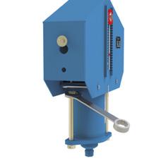
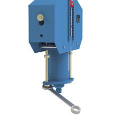
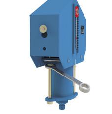
2) Alternate tightening or loosening the two load adjustment bolts, by a turn in each case. The base plate of the load adjustment hood and the lower edge of the constant hanger body must thereby remain parallel.
The procedure is completed as soon as the guide pin no longer lies at the top or the bottom of the blocking device. If, for constant hangers of higher load groups, the necessary adjustment forces are too big and manual adjustment is not possible, auxiliary devices must be used (see point 6, auxiliary devices).
3) Tighten the locknuts of the load adjustment bolts. Now deblocking can continue.
By way of the load adjustment bolts the length of the lever of the leverage arm is altered on the left and right respectively.
On load adjustment the working travel remains unaltered.
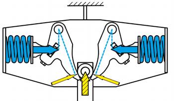
Procedure:
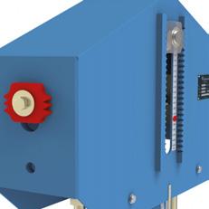
1) Unlock tab washer.
2) Turn load adjustment bolts equally on both sides until the guide pin is free.
3) Secure load adjustment bolts against twisting by locking the tab washers.
Tightening or loosening of the connecting rods, as well as load calibration, can be performed manually on all hangers. For hangers in the higher load groups this work can require a great deal of effort due to the higher load calibration.
To facilitate the work, an auxiliary device can be made available with which a hydraulic load take-up using a handpump can be effected. It is operated by LISEGA personnel.
Installation device, used to relieve the load adjustment bolts
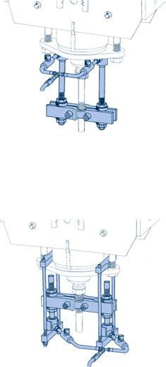
Installation device, used to relieve the adjusting nut
The flawless functioning of the constant hangers and supports can be checked in every operating situation by examining the position of the guide pin.
Under normal operating conditions, maintenance is not required.
ProducT 2 grouP
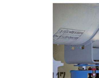
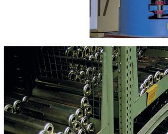
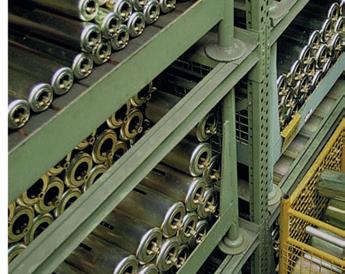
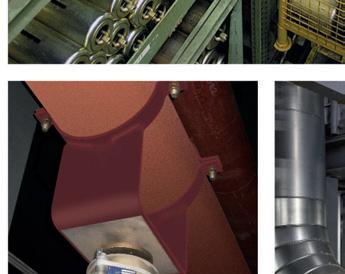
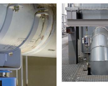
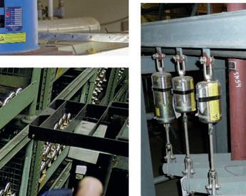
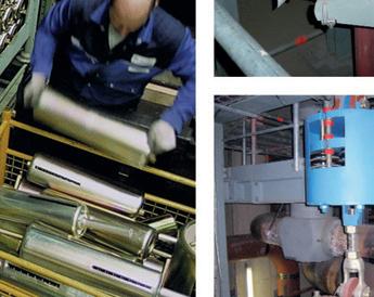
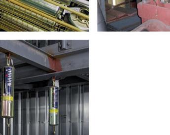
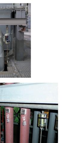
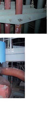

To avoid constraining the system, thermal expansion in high-temperature piping must not be restricted. The piping must therefore be supported in a correspondingly elastic manner.
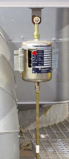
To balance slight vertical displacement in the pipe systems, spring components are used as supports. These components function on the basis of preset helical coil springs which exert a variable supporting load over the range of movement in accordance with their specified spring characteristics. Load variations resulting from this are limited through the stress analysis calculations, depending on the sensitivity of the piping.
The relevant basis for the function of the spring components are specified in the current guidelines (see technical specifications, page 0.5).
A range of spring component designs are available for optimum adaptation to the various structural requirements. The ideal choice depends on the installation situation.
Spring hangers and supports are as a rule calibrated in such a way that the spring force and pipe load are the same in the cold position (see page 0.5). The corresponding hot load position results from the theoretical pipe displacement (travel) and the spring rate.
The difference in force between hot and cold positions acts on the pipe system as a reaction force and is governed by the relevant design specifications. Further information can be found on page 0.5.
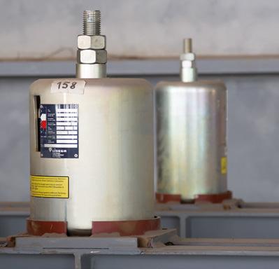
As standard practice, the permissible force deviation between cold position (blocking position) and hot position should not exceed 25 % in relation to the hot load.
Moreover, as a rule constant hangers/supports are used that maintain a constant hanger/support force over the whole displacement range.
The reaction force depends on the spring rate (stiffness) of the respective coil springs. The change in force from cold to hot position results from the displacement. The greater the spring rate, the greater the change in load and accordingly the reaction force in the pipe system. For optimum selection of spring hangers and supports, LISEGA has divided the load ranges into 5 travel ranges.
Details of their application can be found in the selection table (see pages 2.5 and 2.6), in the installation and operating instructions (page 2.19) and the technical specifications (page 0.3).
Spring hangers and supports are checked for function and preset at the factory to the cold or blocking load and blocked in both directions of movement. This enables installation of the support in the designated installation space without time-consuming adjustments.
In addition, the supplementary loads arising through pickling, flushing or pressure testing are held by the blocking devices.
cold and hot positions are shown on the travel scale by white and red marking respectively
the blocking devices have continuously variable settings and can be reused in any spring position
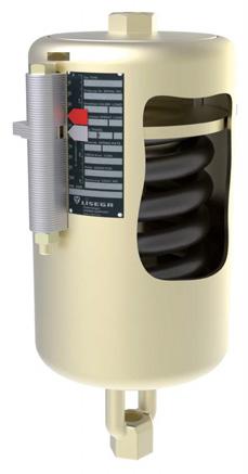
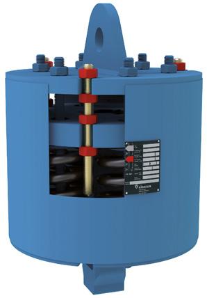
The user can profit from a wide range of special benefits with LISEGA spring hangers.
Significant savings are possible, particularly with regard to ancillary labor-intensive support costs such as planning, installation and operation.
No welding (types 20, 21, 27).
Fully electro galvanized surfaces. For heavy duty designs: coated surfaces.
The cold or blocking position is marked on the travel scale (white arrow).
Fully adjustable blocking system.
On the spring hangers, the preset values are noted on the riveted name plate.
Special prerelaxed springs with a CED (cathodic electrophoretic dip coating) finish prevent any significant loss in load capacity.
Integrated connecting elements.
Variable connection possibilities within the load group selected and the possibility of later adjustment for load setting.
The theoretical hot position (operating position) is marked on the travel scale (red arrow).
Five travel ranges from 0 to 400mm, load group C to load group 9
Three travel ranges from 0 to 200mm, load group 10 to load group 50.
Load application free of moments by coinsiding the load axis with the axis of symmetry.
Favorable performance-to-weight-ratios for reduced assembly weights.
Modular system simplifies selection (load groups and travel ranges).
Flexible installation configurations using standardized components.
Secure connection of load chains through the load and connection compatibility of system components.
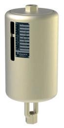
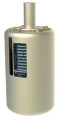
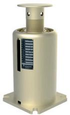
This design is the most commonly used and is fitted with an upper connection for suspension. It is used where the surrounding structure offers a suitable connection point and sufficient installation space. The upper connections can be universally adapted to the existing conditions using standard components.
This version is used especially if the permissible deflection of a support chain when using type 21 was exceeded or if, due to shortage of space, a type 21 spring hanger cannot be installed. The connection is made by a rod fed through the hanger.
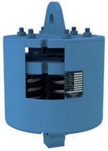
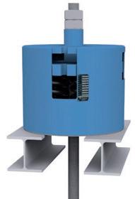
If the surrounding conditions do not permit suspensions, this design offers a suitable alternative as a support. For larger horizontal displacements of the support load and of steel/steel slide plate contact, under certain circumstances the functioning of the support can be adversely affected by any lateral forces generated. It is recommended to avoid this risk by using LISEGA slide plates. In this case the mating components must have a stainless steel surface and if necessary be fitted with a twist restraint.
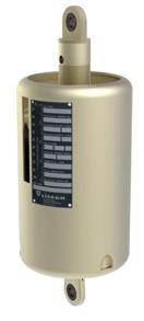
Spring hanger type 22
This design corresponds functionally to type 21 and is available for higher loads up to 400kN.
Spring hanger type 26
This design corresponds functionally to the seated spring hanger type 25 and is available for higher loads up to 400kN.
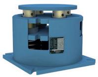
This design corresponds functionally to spring support type 29 and is available for higher loads up to 400kN. Here too, LISEGA sliding components can be used as an option.
In contrast to the type 29 spring supports, lateral displacements can be absorbed practically free of friction forces by this design. This way, resulting forces in all planes, both in vertical as well as horizontal directions of movement, are almost completely eliminated.
The angulating spring supports act in compression. They are fitted on one side with an adjustable load tube and a rotating ball bushing joint and on the other with a fixed ball bushing joint. The joints provide the appropriate connection to the type 35 weld-on brackets and the dynamic clamps in product group 3.
These special components act in compression and tension directions and are used to stabilize the position of pipe systems and other plant equipment. The connection components correspond with those in product group 3 (dynamic components).
With the LISEGA sway braces type 27 the following settings can be made:
load pre-tensioning installation dimensions free stroke
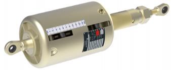
These commonly used components combine the advantages of the spring hanger with the easy-to-install, weld-free plug-in trapezes. For restricted spaces the spring hanger trapezes can be supplied as special welded designs.
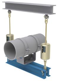
Telescopic spring supports type 29 .. 2.
As a special design of type 29 these telescoping spring supports are used for lower E dimensions. They are fitted as standard with a PTFE slide plate.
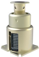
Slide plate for spring supports type 29/28
To reduce friction between the load plate and mating component (e.g. clamp base), PTFE sliding materials (up to 180°C) or suitable material for higher temperatures (up to 350°C) are used. The mating component should in this case have a stainless steel sliding surface. The selection of slide plates can be found on page 2.11.
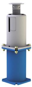
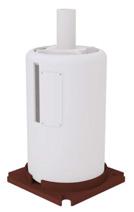
Installation extension for spring support type 29
To bridge larger installation heights, adapted installation extensions can be ordered (see page 2.11).
Base plate for spring hanger type 25
If required, type 25 can be supplied with the base plate type 72 for bolting or welding. A selection can be found on page 2.9.
Sway brace type 27 angled arrangement
Sway brace type 27 simple arrangement
The permissible force variation from cold load (installation load) to hot load (operating load) is limited internationally by the common specifications for pipe system calculations to max 25% of the operating load. In principle however, it is dependent on the pipe systems allowable stress.
To avoid functional variations through instability from springs with long travel, maximum travel of 50mm should not, as a rule, be exceeded.
In order to offer the largest possible field of application while at the same time complying with these specifications, LISEGA spring components are divided into 5 travel ranges with correspondingly different spring rates.
Travel ranges 4 and 5 belong to the ‘extra-long spring travel’ category and should only be used after careful consideration of the travel and variability, especially in sensitive, ‘soft’ pipe systems.
The choice of a suitable design type is dependent on the respective support configuration and/or installation conditions.
The following selection procedures can be followed to determine the most economical component size:
7.5153045600.070.180.541.082.164.338.6617.3326.0034.6643.33 10.0204060800.080.200.581.162.334.669.3318.6628.0037.3346.66 12.52550751000.090.220.621.252.505.0010.0020.0030.0040.0050.00 15.03060901200.100.240.661.332.665.3310.6621.3332.0042.6653.33 17.535701051400.110.260.701.412.835.6611.3322.6634.0045.3356.66 20.040801201600.120.280.751.503.006.0012.0024.0036.0048.0060.00 22.545901351800.130.300.791.583.166.3312.6625.3338.0050.6663.33 25.0501001502000.140.320.831.663.336.6613.3326.6640.0053.3366.66 27.5551101652200.160.340.871.753.507.0014.0028.0042.0056.0070.00 30.0601201802400.170.360.911.833.667.3314.6629.3344.0058.6673.33 32.5651301952600.180.380.951.913.837.6615.3330.6646.0061.3376.66
35.0701402102800.190.401.002.004.008.0016.0032.0048.0064.0080.00
37.5751502253000.200.421.042.084.168.3316.6633.3350.0066.6683.33
40.0801602403200.210.441.082.164.338.6617.3334.6652.0069.3386.66 42.5851702553400.220.461.122.254.509.0018.0036.0054.0072.0090.00 45.0901802703600.230.481.162.334.669.3318.6637.3356.0074.6693.33 47.5951902853800.240.501.202.414.839.6619.3338.6658.0077.3396.66 50.0100 200 3004000.250.521.252.505.0010.0020.0040.0060.0080.00100.00 33.366.6100.0133.3166.6 11.122.244.488.9133.3177.8222.2
In cases where a smaller ‘E’ dimension than that of type 29 ..1. is required, we recommend the use of telescopic spring support type 29 .. 2. (see page 2.17).
1. Selection of the most favorable spring hanger/support
Example:
Operating load F = 6000N
Permissible deviation p 25%
Travel (upwards) s = 15mm
The max. permissible spring rate produces: Spring rate (permissible deviation) (operating load) (working travel)
c 0.25 6000N = 100N/mm 15mm
Selection type 25 42 18
Spring rate c = 66.6N/mm
Cold load FK= 7000N
2. Determination force variation (percentage)
Example:
6000N operating load, working travel 15mm (upwards), a spring hanger type 25 42 18 with a spring rate of c = 66.6 N/mm was selected:
Change in force = (working travel) (spring rate) (operating load) F = 15mm 66.6N/mm = 0.1665 6000N
Spring hangers type 22, spring hangers type 26 for seating, spring supports type 28
25.0 50100106.66133.33160.00200.00266.66 27.5 55110112.00140.00168.00210.00280.00 30.0 60120117.33146.66176.00220.00293.33
32.5 65130122.66153.33184.00230.00306.66
35.0 70140128.00160.00192.00240.00320.00
37.5 75150133.33166.66200.00250.00333.33
40.0 80160138.66173.33208.00260.00346.66
42.5 85170144.00180.00216.00270.00360.00
45.0 90180149.33186.66224.00280.00373.33
47.5 95190154.66193.33232.00290.00386.66 50.0100200160.00200.00240.00300.00400.00
Travel range = 4th digit of type designation. For the availability of the different travel ranges, see dimension tables on pages 2.7 to 2.17.
The use of springs with extralong travel is to be treated with reservation due to the relatively large spring hysteresis.
The actual travel is subject to tolerances and may differ to theoretical values
Spring hanger type 21 C2 19 to 21 95 18 Standard design, delivery from stock.
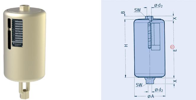
Dimension ‘E’ increases on loading by the corresponding spring travel (see load table on page 2.5).
In restricted spaces the spring hangers can be used with type 79 trapezes (see page 2.14).
1815517M20525525302520.0
21 44 1815517M20920800302529.0
21 51 1818021M24215215363016.5
21 52 1818021M24305305363020.5
21 53 1818021M24540540363032.0
21 54 1818021M241035825363046.0
21 55 1818021M2412751065363057.0
21 61 1822024M30245245463531.0
21 62 1822024M30360360463540.0 21 63 1822024M30640640463562.0
64 1822024M301205980463590.0 21 65 1822024M30149012654635114.0 21 71 1824530M36280285554548.0 21
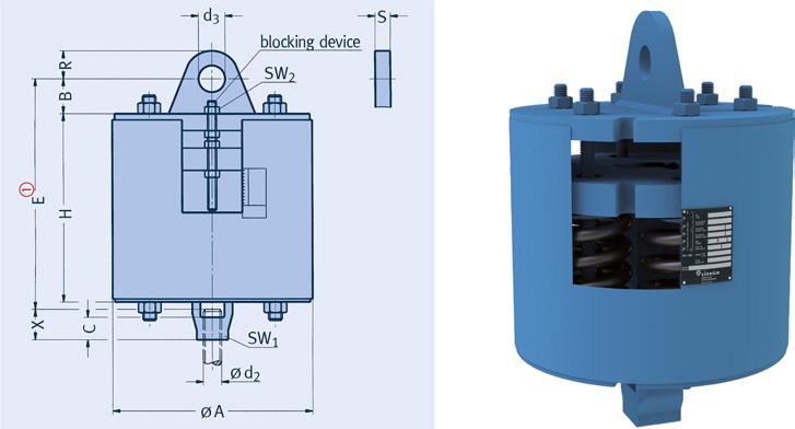
Spring hangers type 22 11 19 to 22 53 19
Dimension ‘E’ increases on loading by the corresponding spring travel (see load table on page 2.6).
22 42 1962511580M72x482685560120351055585515
22 43 1962511580M72x482955830120351055585625
22 52 1964514090M80x492800650135351156595655
22 53 1964514090M80x49211751025135351156595865
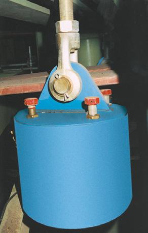
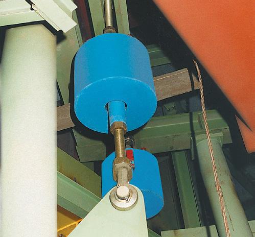
Spring hanger type 22 with weldon clevis type 73 mounted
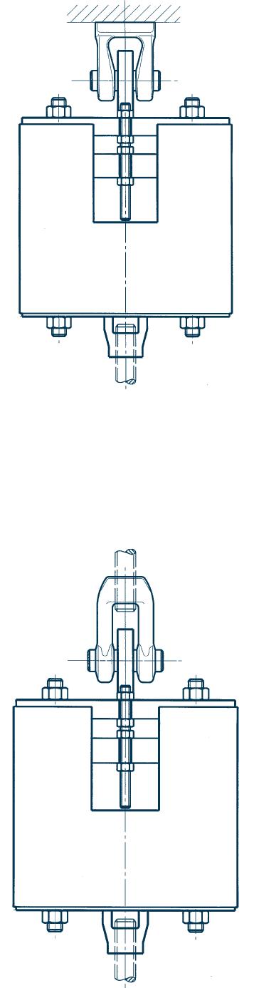
Spring hanger type 22 with threaded clevis type 61 mounted
situations
Spring hangers for seating type 25 D2 19 to 25 93 18 Standard design, delivery from stock. It is recommended to use the type 25 with the base plate type 72.
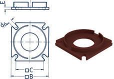
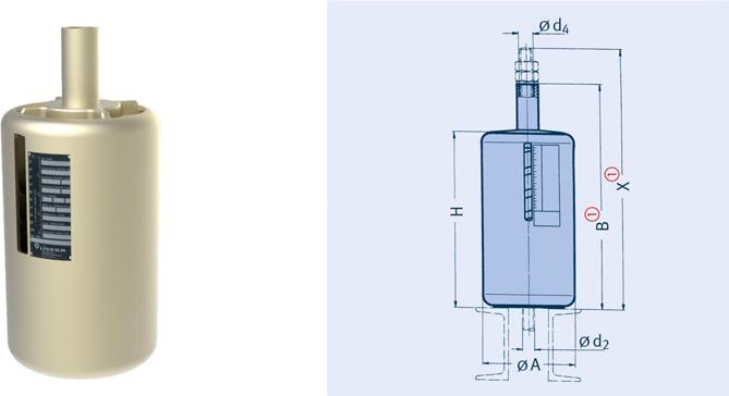
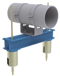
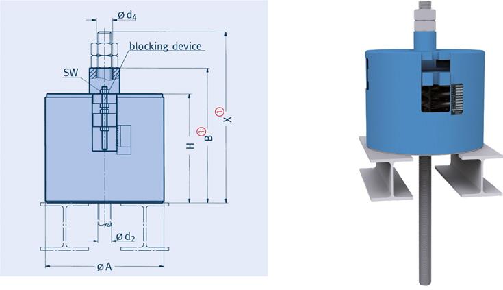
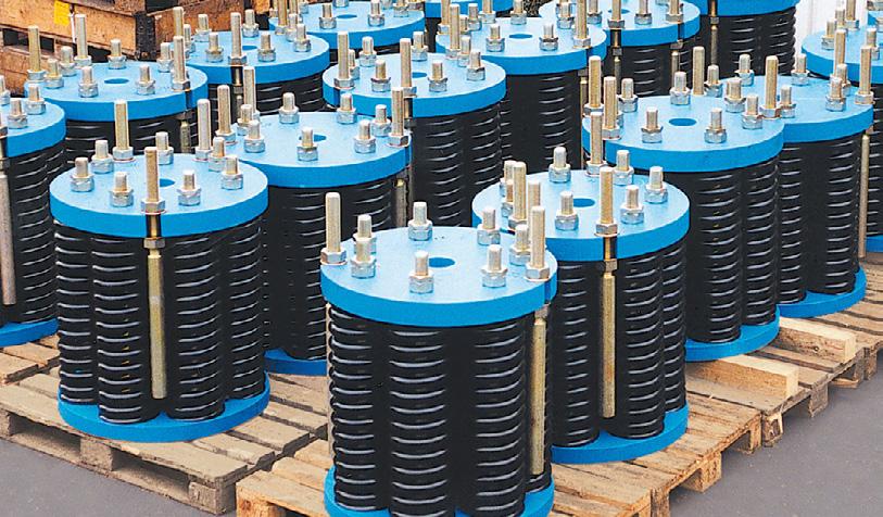
Spring supports type 29 C2 19 to 29 93 18 Standard design, delivery from stock.
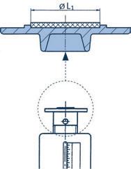
Load plate with integrated slide plate.
When using slide plates the sliding surfaces of the mating components should be fitted with stainless steel plating. This is indicated by the suffix ‘SP’ in the type designation (e.g., clamp base type 49 22 25-SP).
type 29* with slide plate
up to 180°Cup to 350°C Ø L1
29 C2 1729 C2 1640
29 D. 1729 D. 1640
29 1. 1729 1. 1640
29 2. 1729 2. 1640
29 3. 1729 3. 1640
29 4. 1729 4. 1665
29 5. 1729 5. 1665
29 6. 1729 6. 16110
29 7. 1729 7. 16110
29 8. 1729 8. 16150
29 9. 1729 9. 16150
* friction values of the sliding components, see table on page 7.11.
For large horizontal displacements, beside the use of slide plates the use of clamp bases with twist restraints is also recommended.
Order details: spring support type 29 .. .. marking: … set load: …kN travel: …mm up/down
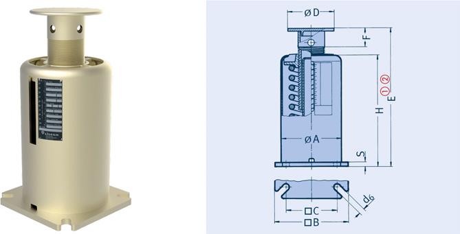
29 23 1811515011514540364601001011.1 29 31 181151501151420536155100126.3
29 32 181151501151431036250100128.4
29 33 1811515011514550364701001213.0
29 41 1815519014018240481801201211.9
29 42 1815519014018360482901201216.0
29 43 1815519014018615485251201225.0
29 51 1818022017018270502101501220.0
29 52 1818022017018370503001501224.3
29 53 1818022017018625505351501237.0
29 61 1822026020023305502451701534.0
29 62 1822026020023430503601701544.0
29 63 1822026020023730506401701568.0
29 71 1824529021523360523002002053.0
29 72 1824529021523500524252002068.0
29 73 1824529021523790526952002097.0
29 81 1824529021527400553352002060.0
29 82 1824529021527575555002002084.0
29 83 18245290215279655587020020133.0
29 91 1827534025533440603702402591.0
29 92 18275340255336256054524025118.0
29 93 182753402553310106091024025173.0
Dimension ‘E’ is independent of the load adjustment; it changes on loading by the respective spring travel (see load table on page 2.5). Adjustment possibility + 30mm.
Type 29 .. 1. is supplied as standard with a electro galvanized load plate without a slide plate. If slide plates are used, the ‘E’ dimension increases by 2.5mm. Please note the recommendation from the table on page 7.12.
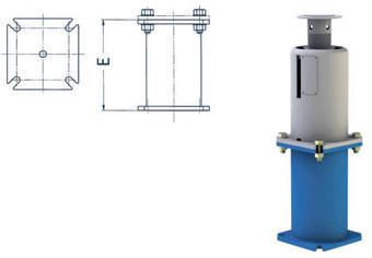
To bridge greater installation heights, adapted installation extensions can be ordered.
.9 15-E…
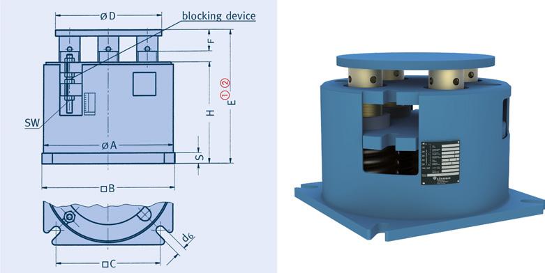
Spring support type 28 11 19 to 28 53 19
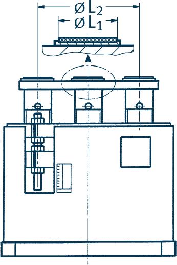
When using slide plates the sliding surfaces of the mating component should be fitted with stainless steel plating. This is indicated by the suffix “SP” in the type designation (e.g., clamp base type 49 97 14-SP).
Dimension ‘E’ is independent of the load adjustment; it changes on loading by the respective spring travel (see load table page 2.6). Adjustment possibility + 30mm.
Type 28 is supplied as standard with a coated load plate without slide plate. When slide plates are used, the ‘E’ dimension increases by 2mm. Please note following tables.
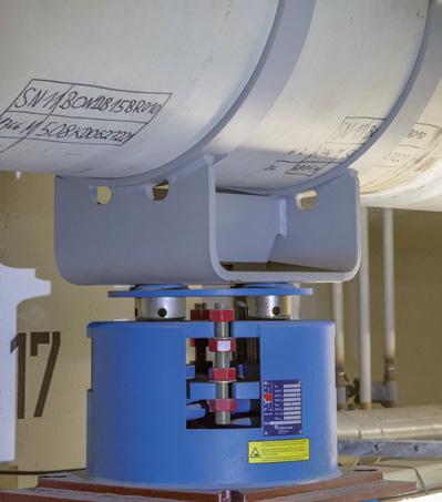
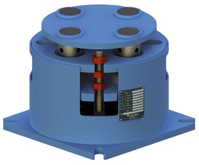
28 1. 1780300
28 2. 1780300
28 3. 17110310
28 4. 17110310
28 5. 17150300 type 28* with slide plate up to 350°C Ø L1 Ø L2
28 1. 1680300
28 2. 1680300
28 3. 16110310
28 4. 16110310
28 5. 16150300
* friction values of slide plates, see table on page 7.11.
Order details: spring support type 28 .. .. marking: ... set load: …kN travel: …mm up/down
Angulating spring supports type 20 D2 19 to 20 93 14 Standard design, delivery from stock.
Dimension ‘E’ is independent of the load adjustment and changes on loading by the respective spring travel (see load table page 2.5). Adjustment possibility + 50mm.
Connection possibilities: see pin diameter of weld-on brackets type 35 or dynamic clamps in product group 3.
Order details:
angulating spring support type 20 .. .. marking: … set load: …kN travel: …mm up/down
Installation extensions for angulating spring supports type 20 D9 19 to 20 99 14
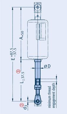
Installation dimensions Emax with load reduction possible. Shorter L dimensions can be supplied, but then without adjustment possibility of 37.5mm.
Order details: installation extension for angulating spring support type 20 .9 .. L = …mm
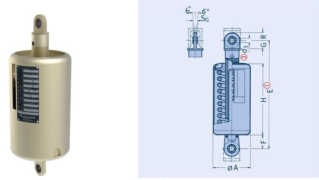
20
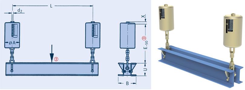
Spring hanger trapezes (bolted version) type 79 D. 19 to 79 9. 19
The 4th digit of the type designation refers to the travel range of the spring hanger 1=50mm, 2=100mm, 3=200mm.
Permissible center loading of the other load cases, see table 4.4.1, page 0.6 (nominal load 120kN, see load group 9).
The ‘E’ dimension increases on loading by the corresponding spring travel (see load table on page 2.5).
79 2. 195M12170029039061080115140152831371.7
79 3. 1910M1690031541063080115140202932391.7
79 3. 1910M161800300395615120115190204145522.7
79 4. 1920M201400345450685120155190255360742.7
79 4. 1920M201800345450685140155200256168823.2
79 5. 1940M2412504054957301401802003077851083.2
79 5. 1940M24180039048071518018023030931011244.4
79 6. 1980M301250445560840200220250351381562005.1
79 6. 1980M302400435550830260220310351741922367.6
79 7. 19120M361800505630900260245310452142442967.6
79 7. 19120M362400500625895300245350452452753279.2
79 8. 19160M4212005607251100260245310502422863787.6
79 8. 19160M4218005557201095300245350502733174109.2
79 9. 19200M4818006107851150300275350603353904959.2
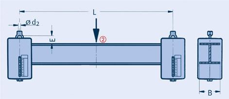
79 D. 111.04M10140080–16201.1
79 1. 11 2.5M1214001001921261.6
79 2. 115M1216001002629352.0
79 3. 1110M1616001002730382.0
79 4. 1120M2017501204148632.7
79 5. 1140M2421001606876994.3
79 6. 1180M3021002001101281726.1
79 7. 11120M3621002401591892418.3
79 8. 11160M4221502601862303229.3
79 9. 11200M48220028024329740310.3
The ‘L’max dimensions can be lengthened by up to 2400mm on reduction of the permissible center loading by 5% per 100mm extension.
When selecting the spring hanger trapeze the weight of the ‘U’ profiles and the clamp base weight must be added to the operating load.
When selecting the spring hanger trapeze, its total weight and the weight of the clamp bases must be added to the operating load.
Order details:
spring hanger trapeze type 79 .. 19 L = …mm, marking: …, set load: …kN travel: …mm up/down
Spring hanger trapezes (welded version) type 79 D. 11 to 79 9. 11
In restricted spaces this version can be supplied as a special design.
Order details: spring hanger trapeze type 79 .. 11 L = …mm, marking: … set load: …kN travel: …mm up/down
Sway braces
type 27 D2 19 to 27 62 19
The maximum working travel including free stroke amounts to 25mm
Load adjustment is made ex works according to customer specifications.
The ‘E’ dimension is independent of the load adjustment; adjustment possibility 37.5mm.
Connection possibilities: see pin diameter of weld-on brackets type 35 or dynamic clamps in Product Group 3.
Order details: sway brace type 27 .2 19 marking: … set load: …kN travel: …mm up/down
Installation extensions for sway braces
type 27 D9 19 to 27 69 19
If required, sway braces can be supplied with installation extensions mounted at the factory.
An exceeding of the maximum lateral displacement of 6° is to avoid.
Installation dimensions Emax on load reduction possible. Shorter L dimensions can be supplied, but then without adjustment possibility of 37.5mm.
Order details: installation extension for sway brace type 27 .9 19 L = …mm
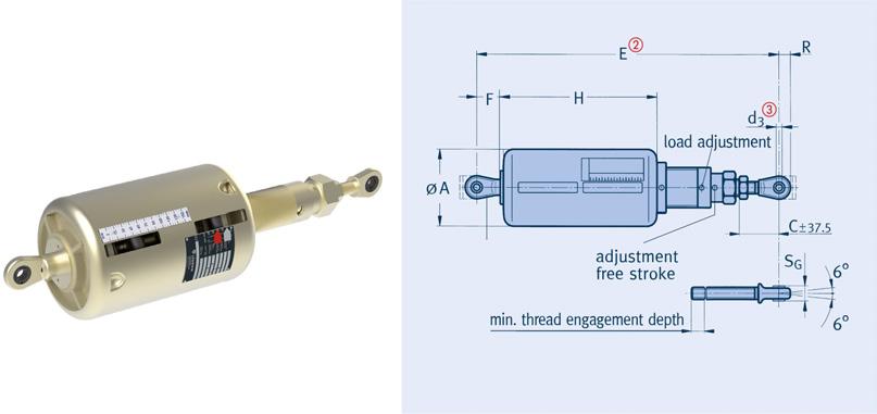
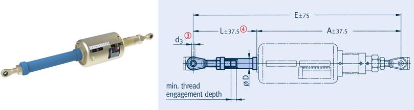
Function diagram
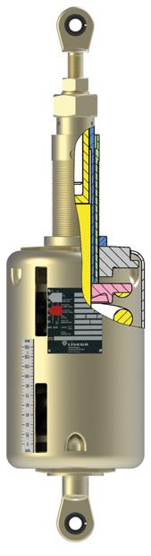
upper ball bushing joint
lock nut
lock nut guide pipe
threaded pipe
lock nut
guide rod
type plate with travel scale
travel scale
lower ball bushing joint spring plate spring
Load and installation length are adjustable for the respective requirements (see installation and operating instructions).
For LISEGA sway braces a free stroke of 0 – 25mm can be set. The travel is reduced in compression and tension directions in accordance with the free stroke selected.
Load transmission on alternating force direction
Spring supports, telescopic type 29 D1 27 to 29 93 27
As a special design of type 29 the telescopic spring supports are used for small E dimensions
The sliding surfaces of the mating component should be fitted with stainless steel plating. This is indicated by the suffix ‘SP’ in the type designation (e.g., clamp base type 49 22 25-SP).
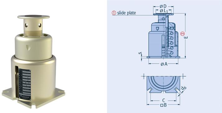
E [mm] = E at min. load [mm] – adjustment load [kN] – min. load [kN] x 1000 spring rate [N/mm]
The telescopic spring support is fitted as standard with a load plate with a PTFE slide plate. If required, this type can also be supplied with a high-temperature slide plate.
The 6th digit of the type designation denotes the design:
7 for standard design with PTFE slide plate (up to 180°C)
6 for design with high-temperature slide plate (up to 350°C).
For friction values of sliding components see table on page 7.11.
The ‘E’ dimension depends on the load setting; it changes on loading by the respective spring travel. Adjustment possibility +20mm.
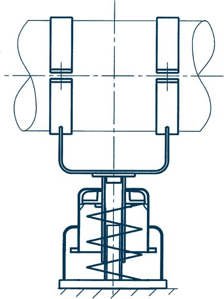
Order details: spring support type 29 .. 2. marking: … set load: …kN travel: …mm up/down
29 13 2.13015512580124085303700.581.254.110.0
29 21 2.1551801451001440102151751.162.533.38.0
29 22 2.1551801451001440103152351.162.516.610.5
29 23 2.1551801451001440105253651.162.58.315.0
29 31 2.1551801451001440122201802.33566.68.5
29 32 2.1551801451001440123202402.33533.311.0
29 33 2.1551801451001440125403802.33516.616.5
29 41 2.1952201801201865122351954.6610133.315.0
29 42 2.1952201801201865123352554.661066.620.0
29 43 2.1952201801201865125604004.661033.329.0
29 51 2.2202452001501865122602209.3320266.624.0
29 52 2.2202452001501865123702909.3320133.330.0
29 53 2.2202452001501865125904309.332066.643.0
29 61 2.275305245170231101830026018.6640533.344.0
29 62 2.275305245170231101841033018.6640266.653.0
29 63 2.275305245170231101867551518.6640133.380.0
29 71 2.300330265200231102032529536.006080063.0
29 72 2.300330265200231102043537536.006040076.0
29 73 2.300330265200231102067555536.0060200105.0
29 81 2.300330270200271502236033553.33801066.671.0
29 82 2.300330270200271502250045053.3380533.391.0
29 83 2.300330270200271502283573553.3380266.6142.0
29 91 2.325370295245331502540037566.661001333.396.0
29 92 2.325370295245331502555550566.66100666.6124.0
29 93 2.325370295245331502587577566.66100333.3181.0
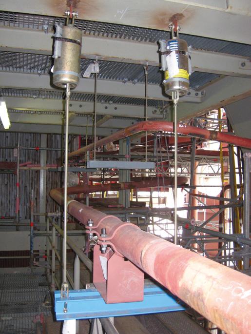
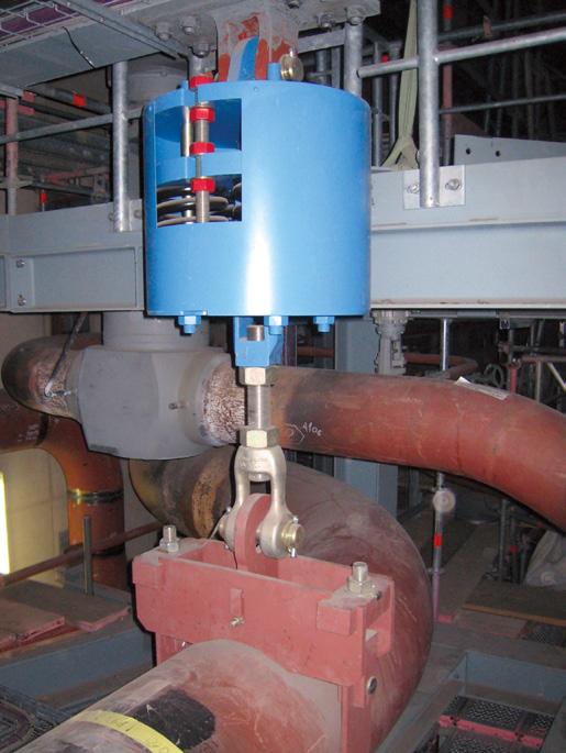
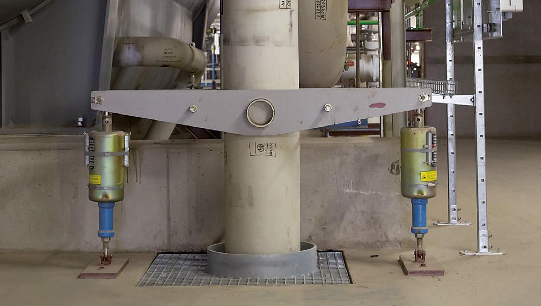
upper connection travel scale
blocking device
name plate
lower connection spring plate
cover plate
securing strap support tube
When transporting, care must be taken that connecting threads and blocking devices are not damaged. When storing in the open air the hangers must be protected from water and dirt.
If not otherwise specified, LISEGA spring hangers are set and blocked at the desired cold position (installation condition). Special blocking devices fix the spring plates in both directions. The adjustment values can be read off the travel scale or name plate.
Stamped on the name plate are:
type number and if required serial number set load and spring rate
Spring hanger type 21 type 22
operating load and travel marking and commission number inspector
On the travel scale the theoretical hot position is marked with a red sticker and the theoretical cold one with a white one. In addition the position of the spring plate on the travel scale is stamped with an “X”. The reading is made at the lower edge of the spring plate (at the upper edge for trapezes type 79 .. 11). The production number is stamped on the body of the spring hanger.
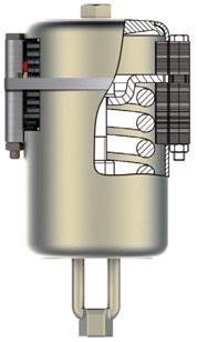
hanger type 21 (blocked)
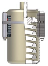
Spring hanger type 25 (blocked)
Spring hanger type 25 type 26
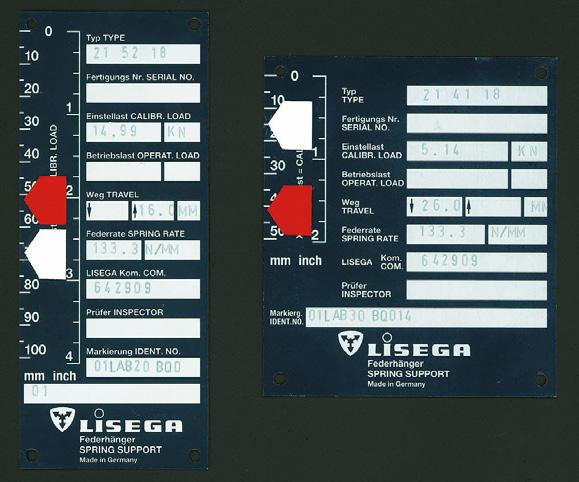
Depending on the connection the spring hangers are fitted at the top with an inner right-hand thread, a lug for connecting pins or a fixed support tube. The threads are greased and sealed with plastic caps. Depending on the design, the lower connection is fitted with a right-hand thread (turnbuckle) or, as with type 25/26, consists of a
The spring supports types 28/29 are equipped with an adjustable support tube with a loosely seated but guided load plate. As delivered the support tube is screwed in and the thread
When installing, the requirements of the installation instructions for the piping systems should be observed, especially the desired instalposition of the connecting rods over the whole load chain. There are two possibilities:
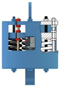
Spring hanger type 22 (blocked)
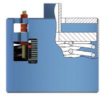
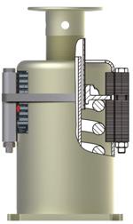
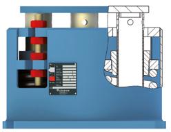
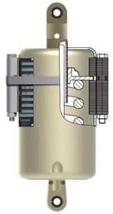
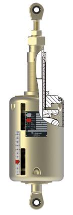
A) The connecting rods are to be installed at an angle to correspond to the expected horizontal displacement of the pipe systems. A perpendicular position in operating condition is to be hereby expected.
B) The connecting rods are to be installed vertically for better controllability. A controlled angled position is thereby permitted in operating conditions.
load plate or ball bushing joint at top
travel scale
stop
name plate
base plate or ball bushing joint at bottom
spring plate
cover plate
securing strap
lock nut
lock nut
guide tube
threaded tube
lock nut
guide rod
Uniform specifications should at all events apply for the whole plant.
The connecting rods and points must be connected by force-locking. Attention must be paid to the minimum engagement depth of the threaded components.
The force-locked connection for type 21 is produced by screwing the connecting rods into the upper and lower connection threads. The lower connection thread is designed as a turnbuckle. Type 22 has a pin-lug upper connection. For adjustment the available turnbuckle length in the spring hanger in each case can be used.
Spring hangers types 25 and 26 are placed on the existing steelwork and correspondingly aligned. The position aligned is to be fixed against horizontal displacement. The force-locked connection is produced via the connecting rod, which is fed through the support tube and tightened and locked with two nuts.
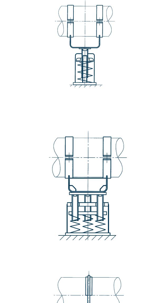
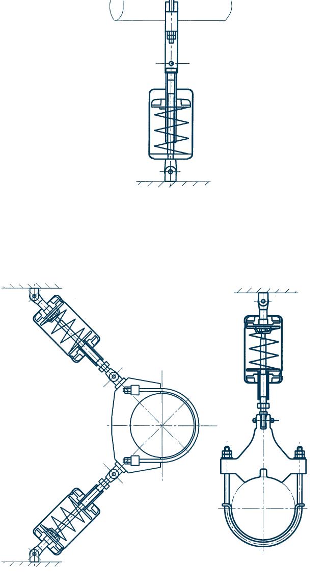
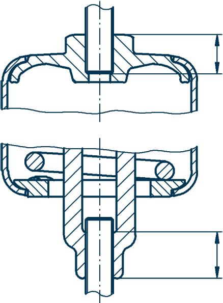
Minimum engagement depth of threaded rods by example of type 21
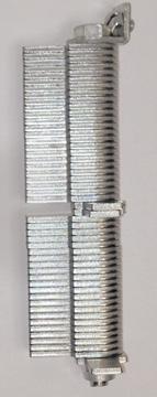
The blocking device for spring hangers and spring supports types 21, 25, 29 and 20 consist of sheet metal lamellas adjustable to any desired load position. Up to 3 blocking devices can be inserted into a spring hanger.
Installation of types 28, 29
The spring supports 28 and 29, are to be connected in the design location by welding or bolting the base plate to the building structure. The load distribution is applied through the load plate and an adjustable support tube (type 29), or several adjustable ones (type 28). To accommodate installation tolerances the support tubes may be further screwed out only to a maximum of 30mm. The instructions on page 7.12 are to be followed for the correct installation of the slide plates.
The angulating spring supports are fitted at the top with an adjustable ball bushing joint and at the bottom with a fixed ball bushing joint or an installation extension – suitable for connection to a weld-on bracket type 35 or to the dynamic clamps type 36 or 37. After alignment of the angulating spring support the lower weld-on bracket is attached to the surrounding structure (see installation instructions for weld-on brackets type 35). The load distribution is applied through the upper pin connection (weld-on bracket or dynamic clamp) to the length-adjustable support tube. To accommodate installation length tolerances the support tube may be further screwed out by a maximum of 50mm.
The sway braces are fitted at the top with an adjustable ball bushing joint and at the bottom with a fixed ball bushing joint or an installation extension – suitable for connection to a weld-on bracket type 35 or to the dynamic clamp type 36 or 37. The load presetting, and if necessary the free stroke, are adjusted at works according to customer specifications. After alignment of the connection points the welding of the weld-on brackets and the connection of the connection pins of the brackets or dynamic clamps types 36/37 are carried out. The adjustable ball bushing joints permit regulation of the installation length by 37.5mm.
The spring hangers/supports may only be deblocked when the set load is fully applied on all the supports making up a support system. If this is the case the blocking devices can be easily removed. If the devices are jammed, the load actually applied does not agree with the theoretical setting (see point 5, load correction).
Procedures for types 21, 25, 29, 20
Removal of the securing strap:
The securing strap is removed with an appropriate tool. Great care must be taken that the free ends of the metal strap do not snap upwards in an uncontrolled way.
Removal of the blocking devices:
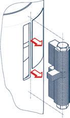
The device is removed from the casing.
When removing the blocking devices, proceed as a matter of principle in a systematic way, step by step, beginning with a fixed point or connection point. Never remove the devices by force!
Storage of blocking devices:
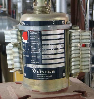
Removed blocking devices must either be stored separately or, for really safe keeping, fixed at the hanger by using the optional LISEGA permanent attachment.
If the original blocking devices have been misplaced and the spring needs to be blocked, e.g. at revisions, they can be supplied by LISEGA at short notice.
Removal of blocking devices:
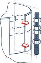
The blocking devices are removed from the casing.
Storage of blocking devices:
Removed blocking devices must either be stored separately or, insofar as sufficient space is available and freedom of movement for the spring plate is allowed, screwed to the cover plate.
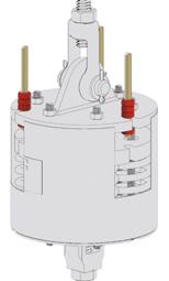
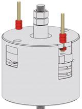
Before every load adjustment, under all circumstances the technical department responsible must be consulted.
Type 21, 22
Load adjustment can be carried out by loosening or tightening the turnbuckle.
Type 25, 26
Load adjustment can be made by loosening or tightening the load nut.
Type 20, 28, 29
Load adjustment can be made by adjusting the support tube of the spring supports.
Load correction and adjustment of the free stroke, type 27
Load adjustment is made by rotating the outer threaded tube (A). For this, loosen the large lock nut (B). To maintain the E dimension the play thereby created must be balanced by readjusting the guide tube (C).
A free stroke can be set for the LISEGA sway braces. For this, the guide tube (C) opposite the inner guide rod (D) must be correspondingly screwed out (loosen middle lock nut (E)). The working travel is reduced in the direction of compression according to the free stroke selected.
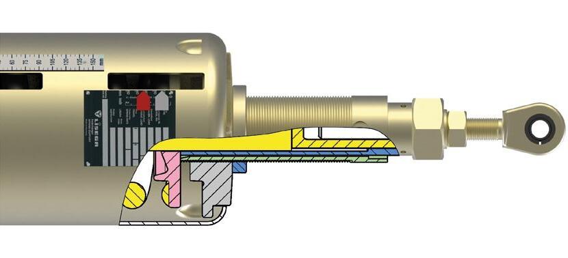
To facilitate load adjustment or deblocking, an auxiliary installation device can be supplied for the higher load groups. The load transfer is then taken up by means of a hydraulic pump. This is operated by LISEGA technicians.
The flawless functioning of the spring hangers can be checked in every operating situation by noting the position of the spring plate.
Under normal operating conditions no maintenance is required.
The blocking devices of types 22, 26 and 28 consist of threaded studs and nuts by means of which any load setting desired can be carried out.
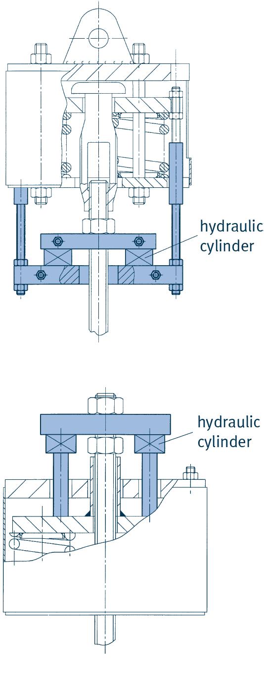
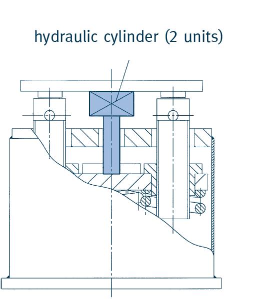
snubbers, rigid struts, energy absorbers, viscoelastic dampers, dynamic clamps
ProducT 3 grouP
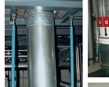
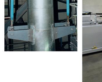
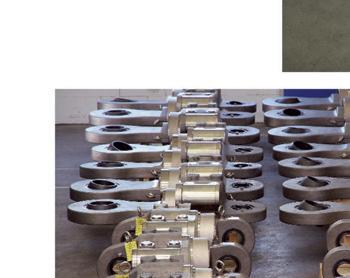
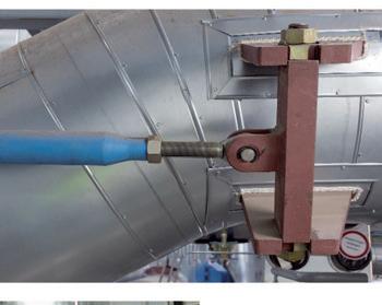
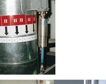
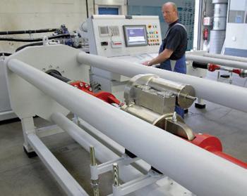

0 1 2 4 5 6 7 8 9 PRODUCT GROUP 3
To avoid unacceptable stresses and moments in the piping systems, unplanned deflections in the piping or other plant components must be prevented. Thermal displacement must, however, not be obstructed!
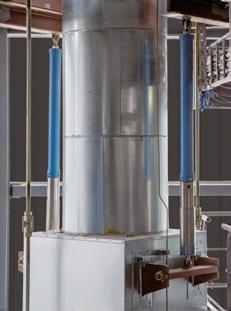
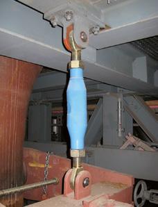
Whenever unplanned dynamic events occur, the support components in LISEGA product group 3 have the task of protecting the piping or other affected parts from damage.
The unwanted jolting displacement of plant components can be caused by:
A. Internal events, for example: start-up / shut-down pressure impacts from valve operations water hammer boiler detonations pipe rupture
B. External events, for example: wind loads seismic events aircraft crashes explosions
Components affected can be: pipe systems pumps valve assemblies pressure vessels steam generators boilers, heat exchangers
For the absorption and transfer of dynamic load cases, specially designed supports are required. With product group 3, LISEGA provides a complete system in which all fields of application are covered by the corresponding ideal component. In this way the implementation of optimum concepts is possible for the user.
LISEGA product group 3 includes the following main products:
Snubbers (shock absorbers), types 30 and 31
Rigid struts, type 39
Energy absorbers, type 32
Viscoelastic dampers, type 3D
Pipe whip restraints, type 3R
For proper implementation of the main components a complete range of connection possibilities are available:
Installation extensions, type 33
Weld-on brackets, type 35
Dynamic clamps, types 36 and 37
Dynamic riser clamps, type 34
The component connections are designed to be compatible with the LISEGA modular system and are subject to uniform calculation criteria. A ‘table of permissible loads’ can be found on page 0.6 of the ‘technical specifications’.
The stress analyses forming the basis correspond to the international guidelines and codes and are additionally supported by practical experiments and testing.
Design Report Summaries according to ASME III NF and RCC-M are available.
The use of snubbers (shock absorbers) is pre-ferred in thermally operating plant components. In a dynamic event, snubbers provide an instantaneous, fixed, practically rigid connection between the component to be secured and the surrounding structure. In this way the dynamic energy from abrupt displacement can at once be transmitted and harmlessly dissipated. The thermal displacements during routine operation are not restricted.
If operational displacements have to be restricted, e.g. in zero crossings, rigid struts are used. These components form rigid connections from connection point to connection point and do not permit movement of any kind in the axial direction. As they are fitted with articulated bearings they permit slight lateral displacement.
If only minor operational displacement is expected at the load application point, energy absorbers can be used. These components allow slight movements limited in the end positions by an adjustable gap. Any components affected are protected from overloading because, due to the design, excess dynamic energy applied is transformed into plastic deformation of the absorber.
Dynamic loads from mechanical, hydrodynamic or other external events can seriously damage plant components and pipe systems. Viscoelastic dampers can absorb these vibrations and load peaks. A highly viscous fluid thereby absorbs the kinetic energy and dampens any vibrations.
Pipe whip restraints are a specially designed type of pipe restraints. In the event of a bursting pipe system, it will transform the suddenly released kinetic energy into plastic deformation and hold the pipe in a safe position. Any overloading of the steelwork is thereby prevented.
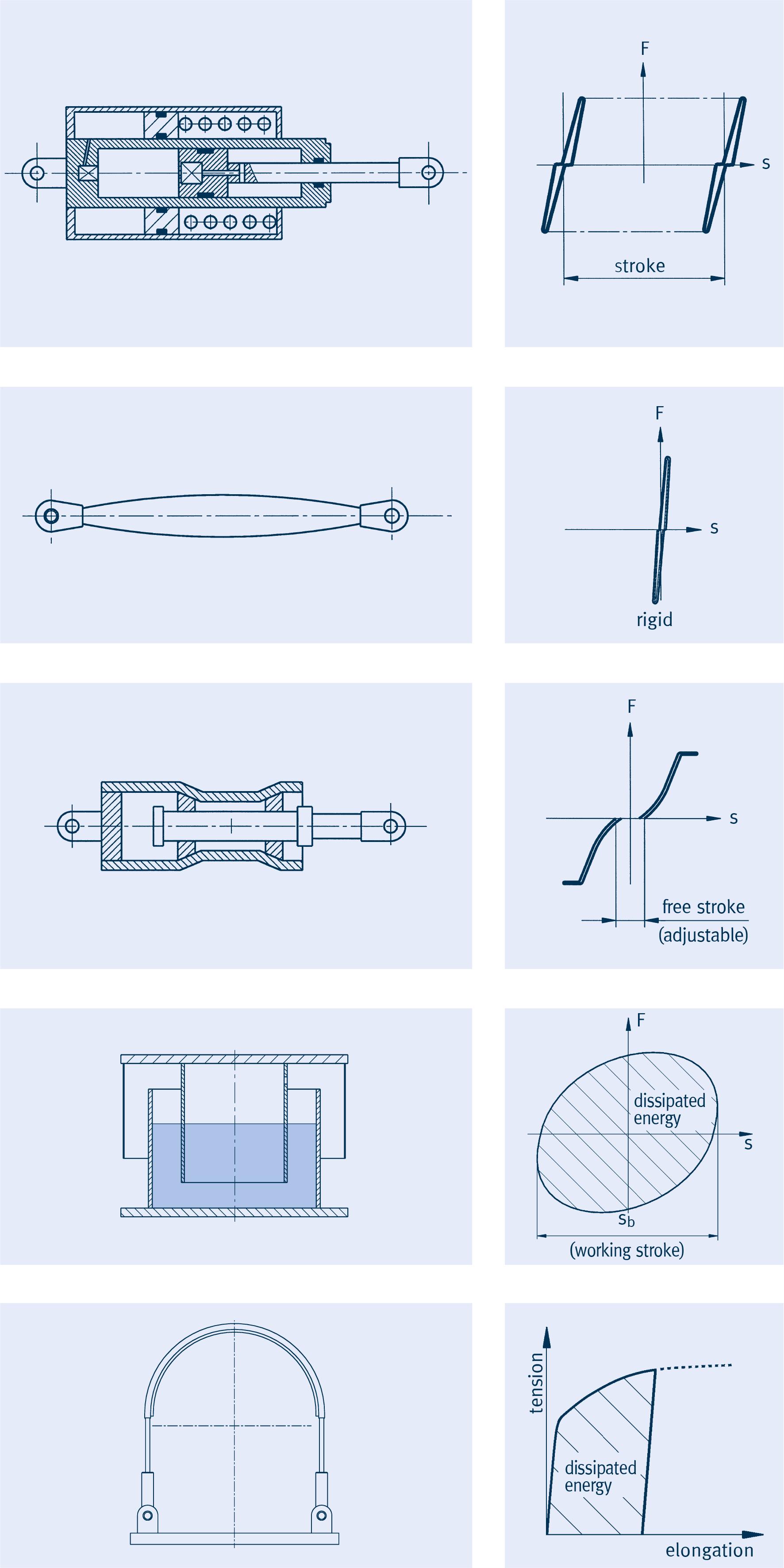
The components in product group 3 are dynamically stressed. When using them, the following points must be observed for their effective functioning:
1. In the conception of dynamic fixed points the rigidity of the whole system, i.e. of all components in the support chain, must be taken into account.
2. In the selection of the sizes to be used, the sum of all loads occurring must be considered.
3. For given loads it must be clearly determined beyond all doubt which design load (H, HZ, HS and/or Level A, B, C, D) the data corresponds to. The ‘table of permissible loads’ on page 0.6 of the ‘technical specifications’ must be observed.
4. The stroke length of snubbers should not be fully utilized. A travel reserve of 10mm in both directions is recommended.
5. When arranging components, sufficient lateral freedom of movement must be ensured so that no jamming occurs at the connections.
6. In the case of parallel arrangement of snubbers it is recommended to take load reserves into account. Instead of 50% in each case, both snubbers should be designed to take at least 70% of the calculation load.
7. The installation drawings should clearly indicate the degree of freedom of possible angulation of the components.
8. Any necessary torque values for threaded connections in the structural attachments should be indicated.
9. Before commissioning the plant, all support points should once again be visually inspected.
10. The LISEGA instructions for commissioning are to be observed, as well as inspection and maintenance recommendations.
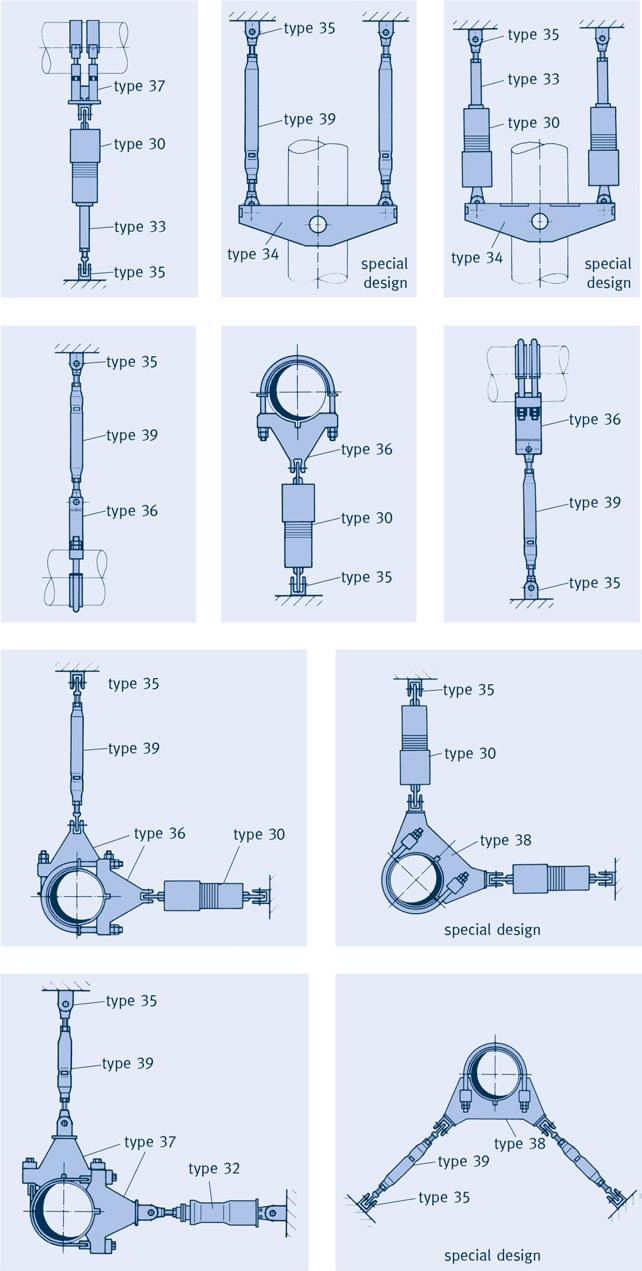
LISEGA snubbers have stood the test of time in practical applications for well over four decades and have thereby proven their outstanding reliability. Extensive operational experience has, together with continuous further development, led to highly acclaimed state-of-the-art products and to worldwide market leadership.
Access to snubbers after installation is almost always difficult and, due to possible danger to personnel from radiation when installed in nuclear power plants, is subject to stringent safety regulations. For this reason the most stringent demands are made on reliable, maintenance-free, continuous functionality.
For the reliable operational safety of snubbers, besides the function principle and whole design, the highest quality of critical components is crucial:
sealing systems piston and rod guides hydraulic fluid sliding surfaces corrosion-resistant materials corrosion-free interiors control valves
The most common cause of failure in snubbers is usually premature wear and tear and corrosion. For this reason LISEGA snubbers are made of corrosion resistant materials. In addition, any form of metallic contact within the unit is eliminated by the use of special guide bands.
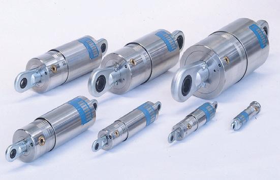
At LISEGA, sealing systems, guides and hydr aulic fluid are certified by reliable qualification procedures to give at least 23 years of troublefree operation under normal operating conditions in a nuclear power station.
The following quality features prove the superior functioning and long life of LISEGA snubbers:
corrosion-resistant materials special sealing systems
vibration-resistant special guides pressurized hydraulic systems dynamic functional behavior exchangeable valves (type 31) tested and approved for min. 23 years maintenance-free operation 60-year design life certified by suitability tests according to KTA 3205.3 approvals according to ASME-NCA 3800
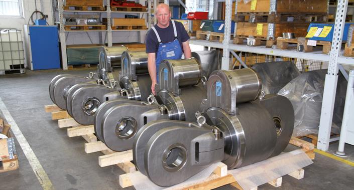
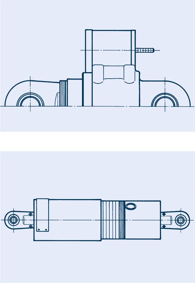
The snubbers form a closed hydraulic system without external bolted pressure fittings. The individual parts of the units are connected without welding by precision fit and screw connections, and are mechanically secured.
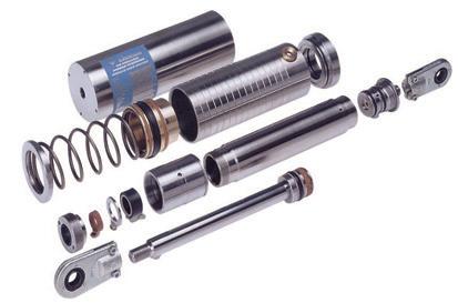
As a protection against corrosion, LISEGA snubbers are manufactured exclusively from corrosion resistant materials. The connecting lugs are made of electro galvanized carbon steel.
The guides on piston rods and pistons are made of a special friction-resistant, non-metallic material.
The compensating reservoir is sealed against the atmosphere by a preloaded piston so that slight excess pressure is maintained in the hydraulic system. This ensures the permanent functioning of all seals and the positive feed of hydraulic fluid to the cylinder regardless of the installed orientation.
The control valves are vital for dynamic function. To achieve high functional accuracy the valve parameters have been optimized by extensive testing and special calculation models.
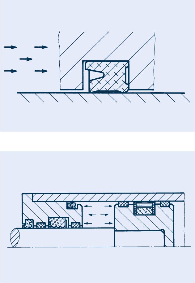
The decisive design features for long-lasting function are the sealing systems. Besides the hydraulic fluid and guide bands, they form part of the non-metallic materials and are therefore exposed to natural aging and wear.
The most important requirement for a long-lasting sealing effect is the choice of the correct sealing material. The crucial factor thereby is the seal’s restitution behavior (‘shape memory’) or compression set, providing the lowest possible stress relaxation.
For optimum utilization of material properties the special shape of the seals are also important, while for final functional efficiency the best combination of the following features are critical:
thermal resistance adiation resistance resistance to wear, especially highfrequency vibrations good restitution behavior (‘shape memory’) good dry run characteristics limited tendency to diffusion in seal surfaces minimal transfer from static to sliding friction (stick-slip effect)
A special mixture of fluorelastomer VITON has proved to offer the optimum solution here. In addition, the following prerequisites must be fulfilled to gain full benefit from the special characteristics:
special sealing geometry supporting composite materials optimum consistency (mixture proportions) optimized hardening precision of sliding surfaces design of the installation spaces for defined preloading of the seals
Ordinary seals do not fulfill these demands in snubbers and have been shown to lead to premature failure. For this reason, as early as 1984 LISEGA, in collaboration with a renowned seal manufacturer, began to develop specific sealing systems that have since proved themselves in practice.
In 1992, after other successful certification procedures through artificial aging and long-term trials, a certification process for LISEGA snubbers was conducted on behalf of a European nuclear operator. The result: a maintenance-free operating period of min. 23 years in nuclear applications was confirmed.
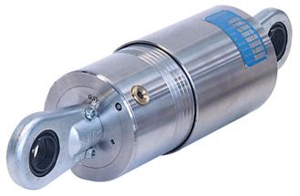
A special range of connection components and adapters are available, so that in the event of an exchange the existing connections on site can still be used.
flange for connection to existing installation extensions
connection special lugs short installation extension without possibility of length adjustment standard installation extension with possibility of length adjustment
33
Connection possibilities: See pin diameters of weld-on brackets type 35 or dynamic clamps in product group 3.
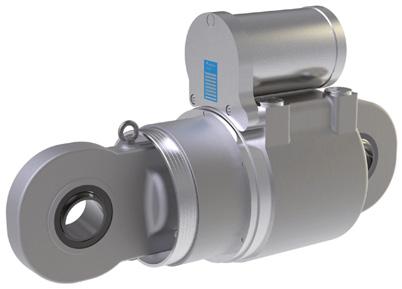
Control valves to achieve greater functional accuracy (type 30: internal).
Name plate with all technically relevant data.
Control indicators: The piston position of the snubbers can be read off on all sides via the scale rings on the snubber casing. A robust steel casing connected to the piston rod serves as an indicator and at the same time protects the piston rod from mechanical damage, pollution and radiant heat.
Connection lugs (carbon steel) electro galvanized (only type 30).
Inspection glass in the compensating reservoir / indicator bar. The fluid level of the reservoir is shown by the position of the reservoir piston. For type 30 the minimum level can be checked through the inspection glass; for type 31 there is a marked indicator bar at the rear of the external compensating reservoir.
The reservoir is sealed against the atmosphere by means of a spring loaded piston so that slight excess pressure in the hydraulic system constantly keeps the seals under slight pressure (type 30: located inside).
Corrosion resistant materials.
Radiation-resistant, wear-resistant seals.
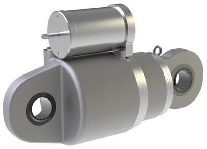
For details of design and materials see technical specifications page 0.1.
In the event of an impact on the component to be secured, an instantaneous, practically rigid connection is to be made between the component and a fixed point on the surrounding structure.
The function of the LISEGA hydraulic snubbers type 30 is controlled by a main control valve (B) positioned axially in the hydraulic piston (A). On slow displacement of the piston ( 2mm/s) the valve is held open by spring force and the hydraulic fluid can freely flow from one cylinder chamber into the other. On rapid piston displacement above a velocity limit (approx. 2mm/s), back pressure develops on the valve disk and closes the valve. The hydraulic flow is interrupted and the displacement blocked. Due to the compressibility of the hydraulic fluids, damaging load peaks are also prevented.
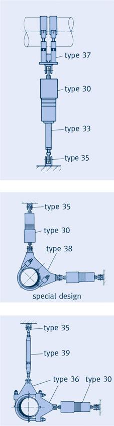
co-axially arranged compensating reservoir (C) takes place. The connection between reservoir chamber and the working cylinder is regulated by the compensating valve (D).
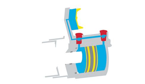
On displacement in pressure direction, the compensating valve (D) also closes almost synchronously with the piston valve.
If the pressure on the closed valve is reduced, e.g. by reversal of the displacement direction, the valve opens independently.
31
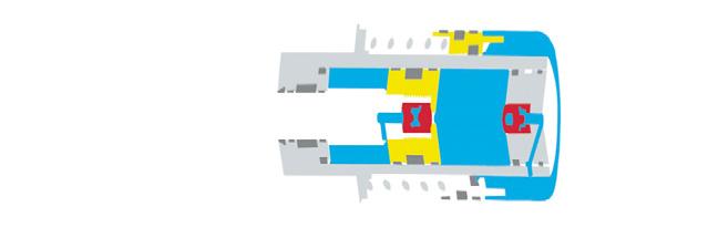
diagram,
To prevent the valves from remaining in a blocked condition they are designed with a bypass system. This permits a gentle after-flow at continuous force and ensures the safe opening of the valves in both cylinder chambers through rapid pressure balance. The compensating valve works synchronously with the main valve in the same way.
To balance the piston rod volume, as well as to change the volume of hydraulic fluid on change of temperature, volume compensation via a
The mode of functioning of the LISEGA hydraulic snubbers type 31 is based in principle on the same concept as for type 30. The particularities of size require a different arrangement of the compensating reservoir (C). At the same time a different arrangement of the valves are also necessary. The valves (B) work similarly to those on type 30. Here too, the flow of hydraulic fluid in the respective direction of movement is interrupted by closure of the corresponding valve a certain limit of velocity is exceeded. As both valves stand with the given arrangement indirect connection with the compensating reservoir, an additional compensating valve is unnecessary.
The valve system is designed to be replaceable, so that all the snubbers type 31 need not be removed for routine function testing. In this way, in the event of a recurrent test only the valve units are replaced by a previously certified valve assembly. A special shut-off device thereby prevents loss of fluid. The replaced valve assembly can subsequently be tested on a test snubber and prepared for future use. This design meet the intent of sub component testing according to ASME OM Code, Subsection ISTD.
Especially stringent safety demands in the nuclear field require flawless proof of the function parameters for snubbers. This applies both to initial delivery inspection and to recurrent tests.
The LISEGA test technology is permanently improved in-house and complies with the most up-to-date technical standards. The test benches function as dynamic Hydropuls® units with optional
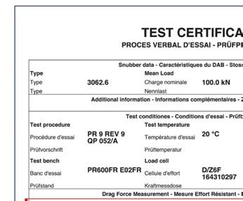
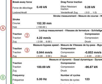
force- or travel-controlled excitation. The frequency bands range from 0.5 – 30Hz, and the test loads from 0.5 up to 8600kN. For standard tests LISEGA has test facilities of its own manufacture in different factories and in various sizes. Mobile units are often used on site at customer request. The test facilities are used worldwide today and are operated by the customers’ own personnel.
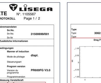
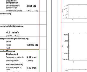
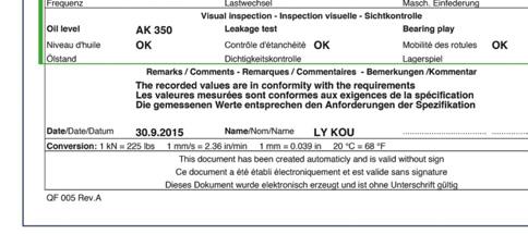
Inspection report with test diagrams page 1
Quasi-static function tests
Drag force [kN]
Lockup speed [mm/s]
Bypass speed [mm/s]
Variable test programs permit the testing of all snubber makes.
LISEGA test benches are also manufactured for customers.
All LISEGA‘s test benches are calibrated at regular intervals on the basis of DIN EN ISO 7500 with calibrated load cells and measurement amplifiers.
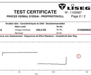
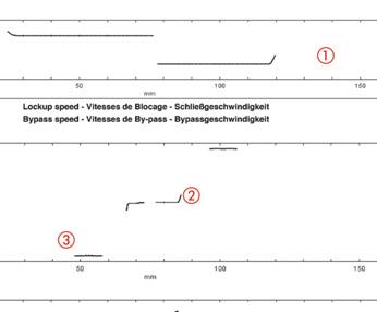
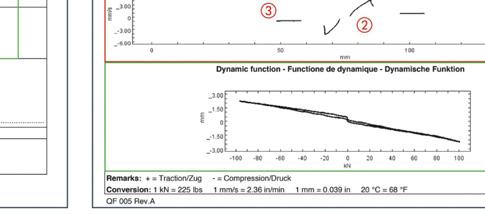
Inspection report with test diagrams page 2
Dynamic function tests
Load and travel amplitude
Operational performance
On dynamic loading, LISEGA snubbers offer a constant, predictable, functional performance subject to the load spectrum.
Specified function values
LISEGA snubbers comply, as a standard, with the following functional data. The values apply to alternating or dynamic loading.
The specified values correspond to the recognized international specifications and practical requirements. Observation of the values is certified and recorded during factory testing.
By means of design adaptation or use of special oil special parameters can be taken into account.
piston rod travel sb at FN, Rt and 1-35Hz 6mm 8mm 10mm 12mm piston rod play sa (lost motion) 0.5mm up till load development on change in load direction
lockup velocity at Rt 2- 6mm/s
bypass velocity at FN und Rt 0.2-2mm/s
maximum resistance against movement (drag force) for FN 8kN 2.5% FN for FN 8kN largest value of 200N or 1%FN largest value of 300N or 1.5%FN 1%FN
Travel range 8 100mm, travel range 2 150mm, travel range 9 200mm.
Rt = room temperature (20°C 4°C). At ambient temperatures of 150°C (short duration, max. 1h) the piston rod travel may be increased by up to 50% due to reduced fluid viscosity.
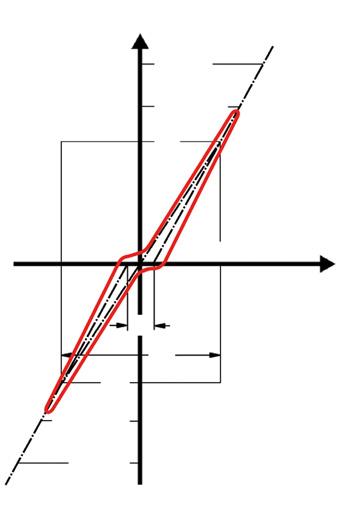
Measured at a constant piston rod speed of approx. 0.3mm/s. Breakaway force is kept at less than 1.5 of given values. FN = nominal load.
If required, sa can be increased to 0.5mm (KTA 3205.3). Bypass velocity 0.2mm/s on request.
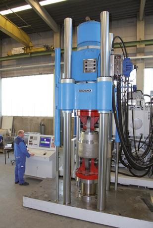
LISEGA hydraulic snubbers are designed as standard for the following operational demands. The specified values are certified by KTA suitability tests.
loading due to ambient temperature
Other values can be agreed in exceptional cases by design adaptations.
continuous operation max. 80°C
short-term max. 1h/temp. cycle max. 40h/year max. 150°C
relative air humidity at 10-150°C
wet steam atmosphere up to max. 150°C X=1 energy dose
The values apply to the whole snubber, incl. seals and hydraulic fluid. The data for the fluid are:
Proof of operational durability is based on the following accumulated load cycles:
load FN
100% (Level A/B)
133% (Level C) ....................
172% (LeveI D) .....................10
The load cycle figures correspond to an assumed maximum dynamic load capacity from diverse load events over a period of 40 years. They also comply to the requirements of the test programs of the KTA suitability tests performed. The test results certify that the snubbers endure these loads while maintaining their operational capability.
Due to their specially designed guides, the snubbers are extremely resilient to any continuous operational vibrations. This is proven by confirmed practical experience.
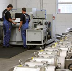
It should be taken into account that the number of possible active parameters, such as frequencies, amplitudes, forms of vibration, effective directions, as well as any possible simultanity, allow no uniform definition of permanent operational vibrations.
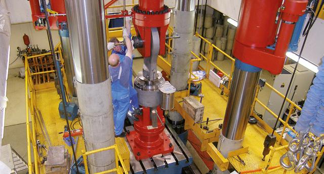
In contemporary support concepts, rigid struts play an important role in the safe guiding of pipe systems. The reliable positioning of piping is a crucial factor in the operational safety and long life of the whole system.
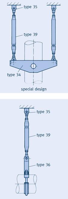
The LISEGA rigid struts type 39 provide a range of important functions for the operational safety of pipe systems:
Transmission of displacement from unplanned load events (see page 3.1)
Guiding of pipe systems for the control of planned thermal displacement direction
Stabilization of flexible pipe systems by fixed so-called ‘zero positions’ Design of axial stops
Rigid struts perform as hinged rigid connections between pipe systems and structure. No resistance is offered to slight displacements in the pipe system around the angular displacement of the rigid struts. Movement axially to the rigid strut is not possible.
The rigid strut consists of a rigid body with a ball bushing joint for connection at each end. Attachment to the structure is made via a weldon bracket type 35 and connection to the piping using dynamic clamps from product group 3. The selection tables for connecting components can be found on page 3.22 or pages 3.29 to 3.43.
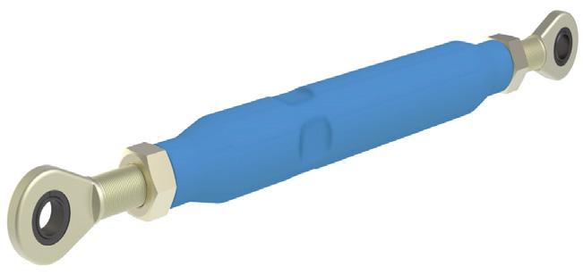
Up to load group 8 the body consists of a tube tapered at the ends, depending on alternative manufacturing technologies.
The shape corresponds to the flow of force and permits a favourable power / weight ratio. The connections are ball bushing joints acting as turnbuckles with right- and left-hand threads, permitting length adjustment within a range of 150mm or 300mm. Flat faces on the body of the tube allow the safe use of a wrench and so facilitate length adjustments in the installed condition.
The ball bushing joints are provided with fine threading to guarantee secure locking.
The bodies are produced in standard lengths and are available from stock. LISEGA rigid struts are suitability-tested according to KTA 3205.3 and designed in accordance with the ASME-BPV Code.
surface with standard paint coating. flat face for easy adjustment. length-adjustable with right-hand / left-hand threads.
body, free of welding up to load group 8. electro galvanized ball bushing joints with fine thread.
safe locking of ball bushing joints by means of fine threads and electro galvanized lock nuts.
The energy absorber functions by means of an adjustable free stroke to absorb thermal displacement. The adjustment of the free stroke can be carried out (for medium sizes) within a range of 25mm. In this range the pipe system can move freely without resistance.
Dynamic events, however, are limited in their movement by the use of stops. The forces arising are thereby led into the building structure up to the specified nominal load and, above that, transformed into deformation energy. Connected components are in this way protected in a controlled manner from overloading.
For this reason energy absorbers are ideal as protection:
against water hammer as a substitute for complex framework constructions as whip restraints
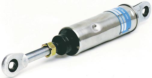
If such an event has occurred, the forward thrust of the disk affected can be read from the position of the indicator bar (G).
For further use of the energy absorber the free stroke on the adjustment device (H) only needs to be re-regulated for the new position. Corresponding procedures can be repeated up to maximum deformation travel (s). Further information is available on page 3.23.
The energy absorbers are designed in accordance with the load group in product group 3 (dynamic components) and are correspondingly compatible in respect of loads and connections with the connection components in this product group. Please also note the instructions on page 3.1.
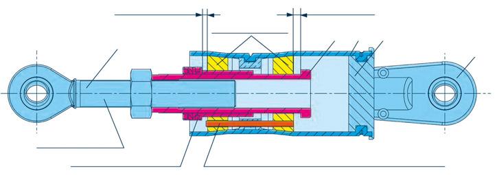
The design consists of an austenitic tubular casing (A) with defined size, into which taper disks (B) with defined force have been pressed. The tube is sealed with a fixed base (C) fitted with a connecting lug (D). The force transmission over the whole unit is made via the stops (E) and the push rod (F).
If a dynamic event exceeds the compression force of the taper disks, the taper disk affected is driven forward and widens the cover tube. In this way the excess force is diverted from the connection components by transformation into deformation energy.
LISEGA energy absorbers have gone through an exhaustive test program to prove their functional reliability. In numerous dynamic and static stress tests, as well as load capacity tests, their safety has been clearly demonstrated.
Energy absorbers are maintenance-free during operation and require no in-service testing.
Energy absorbers restrict dynamic deflections and transform forces above the nominal load into deformation energy. The steelwork is thus protected.
Energy absorber, used instead of a double guide. In this way the framework can be avoided.
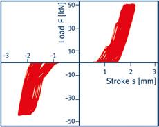
Measured force/travel path with oscillating loads nominal load
Dynamic loads from mechanical, hydrodynamic or external events can severely damage pipe systems and other plant components. Viscoelastic dampers can considerably reduce such vibrations.
Vibrations occur through inner events from mechanical or hydrodynamic processes, or in the case of external events such as wind loads, traffic vibrations or earthquakes.
Impermissibly high vibrations can thereby cause serious damage to pipe systems. By means of special components they must be protected. To avoid stresses in the whole system, displacements from thermal expansion in the piping system may only be minimally obstructed.
Viscoelastic dampers have proved in practice to offer reliable protection for pipe systems and installations. In particular, vibrations caused by sudden peak loads can be reduced to an acceptable level by such dampers.
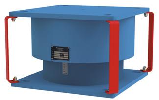
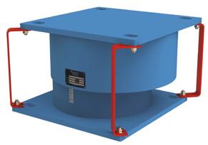
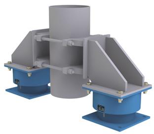
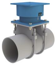
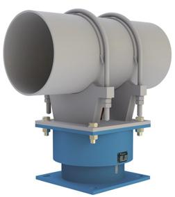
The LISEGA viscoelastic damper consists of a casing filled with viscous fluid that allows relative displacement between the connecting plates and at the same time dampens in all directions, dissipating the kinetic energy (transformed into heat).
Viscoelastic dampers transmit only dynamic loads, not static ones. The reaction force of the damper is thereby proportional to the velocity and frequency of the vibrations. LISEGA offers fluids with varying damping characteristics in relation to application temperature and frequency.
connecting plates
name plate
position indicator
maintenance-free dust cover transport brackets
inner connection thread M16 for transport purposes
load range 2.5kN to 100kN
frequency range up to 35Hz
temperature range from – 10°C to 80°C
travel range up to 50mm
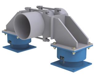
Special designs in the field of dynamic pipe supports are pipe whip restraints. Beside energy absorber type 32, a design type with round-steel U-bolts has proved widely successful, especially for large loads.
Pipe whip restraints are common in nuclear installations and are designed to instantaneously absorb the kinetic energy of bursting pipe systems in faulted conditions. For this, the elongation behavior of the surrounding steel U-bolts is utilized; these are designed to cope with the dynamic forces to be expected.
Pipe whip restraints are designed according to the customer’s design parameters and manufactured by LISEGA as special components.
Pipe whip restraints are important as safety elements and are therefore subject to stringent quality requirements with regard to design and manufacture. As the result of countless deliveries to modern nuclear installations LISEGA has clearly proved its qualification for the supply of these components.
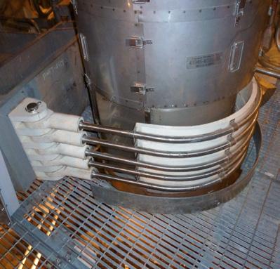
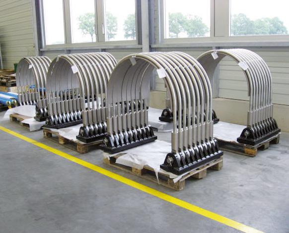
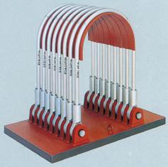
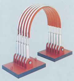
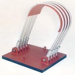
For the dynamic supports the pipe clamp design must also be carefully considered. Despite properly functioning main components (rigid struts, snubbers, energy absorbers) the functioning of the whole system can be seriously affected by faulty pipe clamps.
In the high temperature range and/or over a longer period of time, friction fit clamps cannot safely transmit dynamic loads, even with bolt pre-stressing, due to the creep strength behavior of the materials (long-term fatigue). Even over-sized bolts, which might under certain circumstances severely constrict the piping (‘pipe squeezers’), are not solving the problem.
A typical fault is a clamp design that is too ‘soft’, so that the necessary stiffness rule is not achieved
Attention must also be paid to connections to clamps free of play
To prevent constraints, sufficient space must be ensured for lateral displacement in the event of pipe system movements
To transmit dynamic loads, clamps are required that absorb dynamic forces and transmit them further. Dynamic forces are created by alternating loads; displacement can thereby result due to eccentrically applied forces. The dynamic clamp should therefore be form-fitted (shear lugs) to prevent contortion. In this way, defined, verifiable conditions are produced. Certification is the responsibility of the pipe system designer.
The shear lugs keep the dynamic clamps in the expected force direction and are practically unstressed. Lateral forces would not occur under dynamic load cases because friction forces between the pipe and the clamp insure the firm positioning.
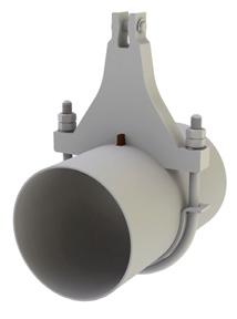
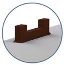
Due to the minimal forces to be absorbed the weld seam stresses can be minimalized, despite the small shear lug sizes. As a rule they lie under 35% of the yield stress (creep strength) limit for load case H (level A/B), in accordance with the permissible ASME or DIN values. From a table the LISEGA shear lugs can be selected on page. 3.44.
To achieve the optimum solution in each case and at the same time the most favorable performance/weight ratios, LISEGA offers 4 standard designs.
The selection tables are classified according to pipe diameters. The type designation for the relevant clamp is found by way of the temper-
ature ranges and permissible loads. After that the installation dimensions must be checked against the scale drawings. Special attention must be paid to the lug connections on the rigid struts, snubbers or energy absorbers. If the standard pin connection d1 is not suitable, a different weld-on bracket type 35 can be supplied. The ‘E’ dimension of the clamp is changed according to the table below.
If the customer order does not show a particular modification of the layout, the bracket connection is fitted so that the main angulation range runs along the pipe axis.
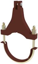
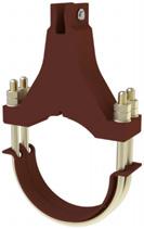
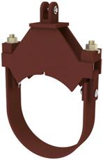
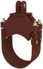
of the Emax dimension for dynamic clamps type 36 and 37 on selection of a smaller connection than given in the column 'max. load group' in the selection tables.
For the support of austenitic pipe systems, the pipe clamps can be fitted with stainless steel inlay plates made of stainless steel 1.4301 (X5 CrNi 1810). These plates must be ordered separately, see page 4.7.
The specified permissible loads (in the selection tables on pages 3.29 to 3.43) are designed for dynamic operation with snubbers or rigid struts according to the load spectrum on page 3.10.
The dynamic clamps can also be exposed to permanent static stress. For this, the specified permissible stresses are reduced according to the following table:
In some cases special designs are advisable in addition to the dynamic clamps type 36 and 37. In particular, for parallel and angulating arrangements, standardized design and calculation methods have been proved successful.
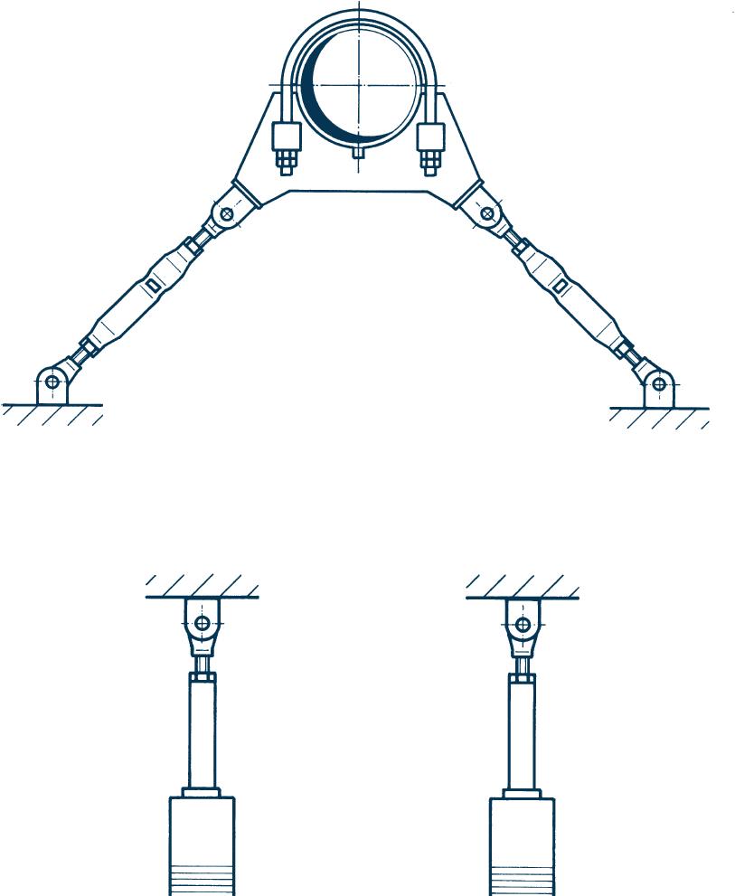
501°C – 510°C 80%
511°C – 530°C 65%
531°C – 560°C 55%
561°C – 580°C 65%
581°C – 600°C 60%
These specifications relate to the creep strength dependent on time in the 200,000 h range at temperature 450°C.
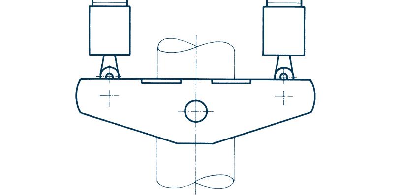
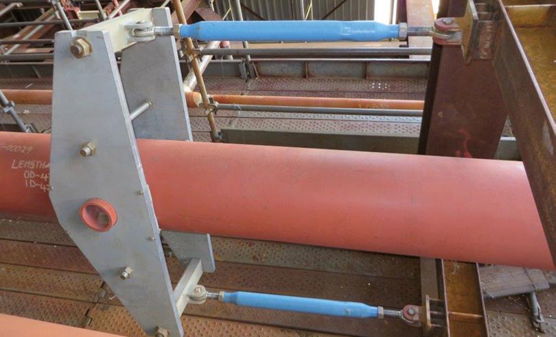
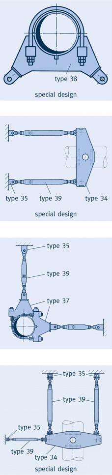
Dynamic stresses frequently arise in the direction of the pipe axis (e.g. from shock impacts or other forms of excitation). To absorb these loads the special dynamic clamp type 34 was developed.
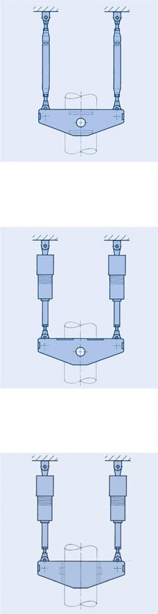
In vertically and horizontally running pipe systems, special clamps are being increasingly used for the defined determination of the pipe system positioning and also for the absorption of dynamic stresses in the direction of the pipe axis. The loads thereby occurring must be distributed via a form-fitting connection to the piping (trunnions). For this purpose LISEGA has developed the dynamic clamp type 34.
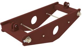
The basis of this design was the long time successful box-frame clamp type 46/48. The load distribution in dynamic clamp type 34 is effected by the use of reinforced cross-beams with weld-on brackets type 35 for connection to the dynamic main products type 30, 32, 39.
For the design of the dynamic clamps type 34 the following parameters are required:
load (dynamic, static)
pipe system temperature insulation thickness span width of the connections connection size and alignment of weld-on brackets type 35
trunnion sizes
trunnion tolerances
position (horizontal/vertical)
main components connected (type 30, 39, 32)
twist restraint/recess dimensions if required
spacer if required
Due to the wide range of possible combinations and design parameters, dynamic clamps type 34 are designed individually on request.
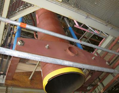
Position securing measures ensure that the clamp cannot angle around the pipe (with the trunnion as pivot). The position-securing device is not dynamically stressed. It is either a recess in the trunnion socket-hole or additional plates.
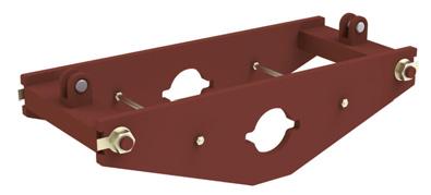
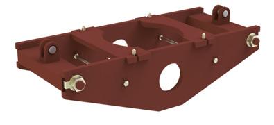
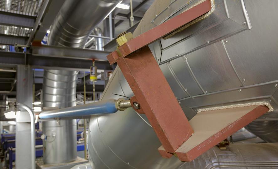
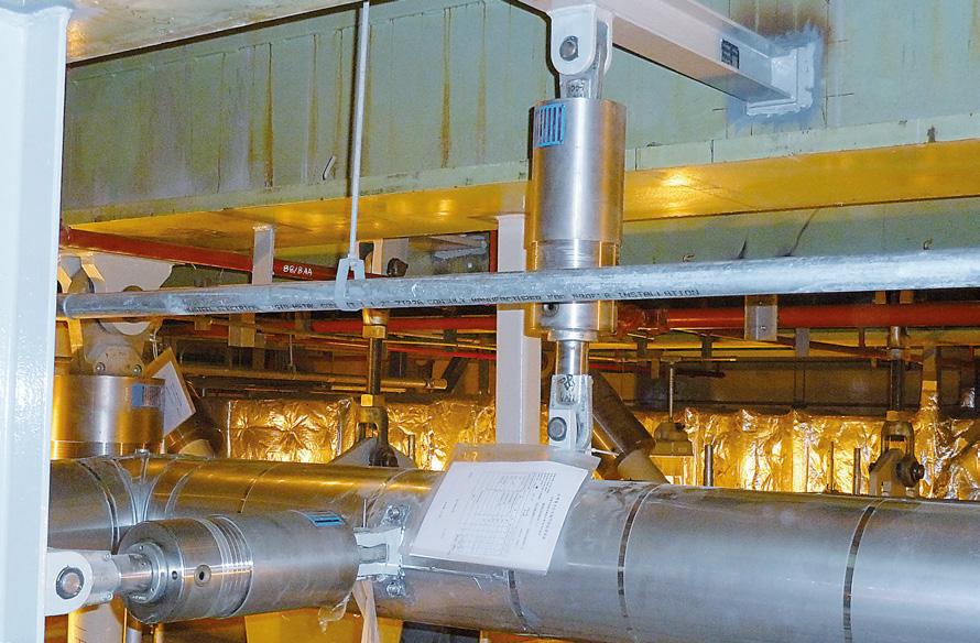
Snubbers
type 30 18 16 to 30 03 12
Serial standard design. Delivery from stock.
Only corrosion-resistant materials are used.
The connecting lugs attached by a connection thread (material P250GH, C45E+QT, S355J2, A668Cl. C/F, SA299) are electro galvanized.
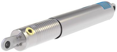
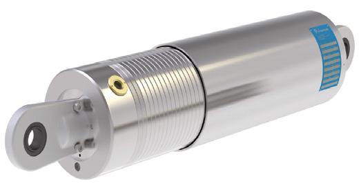
Order details:
snubber type 30 .. .. with 2 weld-on brackets type 35 .. .. marking: ...
30 42 161823.915085153955455822.5128.3
30 62 1610014115017030535685100452237
30 63 1610014130017030685985100452251
30 72 1620026715020050615765130603561
30 73 16200267300200507651065130603578
30 82 16350472150270607308801657544122
30 83 163504723002706088011801657544147
30 92 135507351503007076091016510549175
30 93 1355073530030070910121016510549207
30 02 1210001335150390100935108524014770390
30 03 12100013353003901001085138524014770460
See technical specifications, table: ‘permissible loads’ (page 0.6) and ‘welding of weld-on brackets’ (page 3.22).
Usual design load for earthquakes and similar load cases. See also technical specifications on page 0.6.
Emin = piston rod retracted
Emax = piston rod extended
To bridge greater installation lengths, installation extensions type 33 (page 3.21) can be used.
On replacement of other makes, the connection dimensions such as pin diameters and lug lengths can be adapted to the connection designs already existing in the plant.
If required, snubbers with longer strokes can be supplied.
Connection possibilities: see pin diameters of weld-on bracket type 35 or dynamic clamps in product group 3.
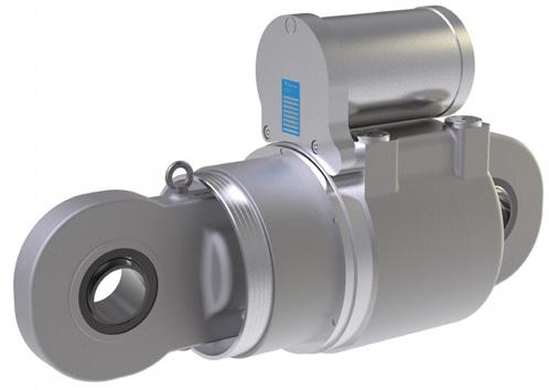
Snubbers type 31 98 16 to 31 58 16
Snubbers type 31 are specially conceived for the absorption of particularly heavy loads. They are mainly used in nuclear power stations to protect steam generators and large pumps. Due to the normally very restricted installation space they are typically custombuilt for the given conditions. The table on this page therefore serves as general orientation for initial planning.
The body and connecting lugs are made of high-tensile stainless steel castings.
See technical specifications, table: ‘permissible loads’ (page 0.6) and ‘welding of weld-on brackets’ (page 3.22).
Usual design load for earthquakes and similar load cases. See also technical specifications on page 0.6.
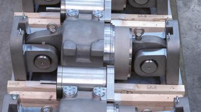
Emin = piston rod retracted Emax = piston rod extended.
Lmax at 80˚C.
Design of travel indicator for travel range 8 (100mm stroke).
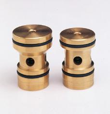
Order details: snubber type 31 .. .. with 2 weld-on brackets type 35 .. .. marking: ...
Connection possibilities: see pin diameters of weld-on brackets type 35 or dynamic clamps in product group 3.
LISEGA snubbers type 31 are fitted with exchangeable valves for in-service tests on site.
Installation extensions type 33 18 18 to 33 03 12 Serial standard design.
Type 33 installation extensions are used if greater installation lengths are required.
Connection to the snubber or energy absorber is made at the cylinder base. By means of serially-produced screw connections the change over easily be made from standard connecting lugs to installation extensions. This also applies to special connections, which are particularly useful when exchanging other makes, as in this way the connections on site can still be used. Further connection possibilities can be found on page 3.6.
An exceeding of the maximum lateral displacement of 6° is to avoid.
Material: tube P355NH ball P250GH bushing C45E+QT joints S355J2 42CrMo4+QT
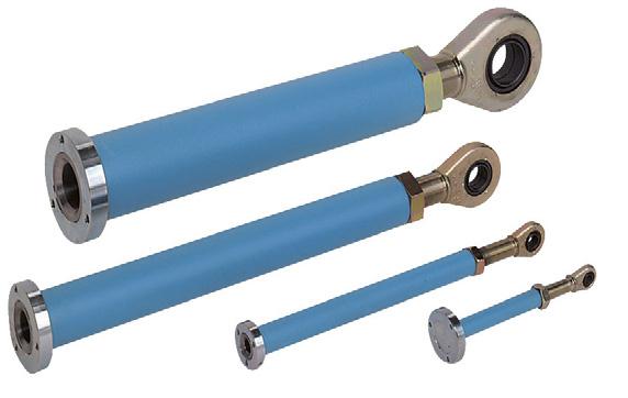
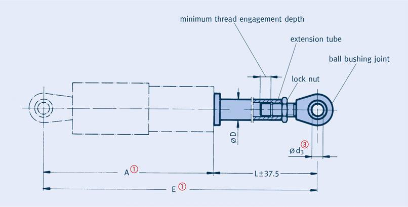
Order details:
installation extension type 33 .. .. L = ...mm for hydr. snubber or energy absorber
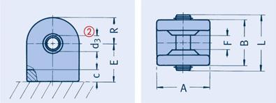
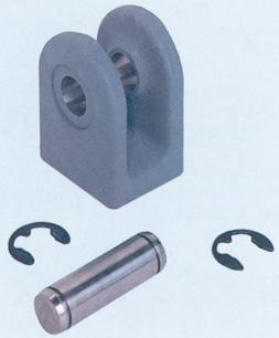
35
35
35
35
35
See technical specifications, table ‘permissible loads’ (page 0.6) and ‘welding of weld-on brackets’ (as shown below).
If required, weld-on / bolt-on brackets in larger sizes are suppliable
35
35
35
35 89 1914.518.021.0
35 99 1115.020.023.0
35 09 1314.017.019.0
35 20 1923.0–
Weld-on brackets should always be arranged so that the max. angulation results in the direction of the greatest thermal expansion during operation . The lateral deflection is restricted to 6° . Misalignment of the weld-on brackets should be avoided due to the restricted possibility of movement caused.
The minimum weld seam thickness ‘ ’ for weldon brackets type 35 is dependent on the angulations and . In the calculations a permissible stress of 90N/mm2 in load case H (level A/B) was assumed.
On increasing the angulation to 90°, the permissible loads are reduced by approx. 15% on constant weld seam thickness ( at = 45˚).
The basis for the permissible loads is provided by the relevant load table (‘technical specifications‘, page 0.6).
Weld-on brackets type 35 19 13 to 35 20 19 Serial standard design.
This component is designed for connection of snubbers type 30 and 31, energy absorbers type 32 and for rigid struts type 39, 16, 20 and 27 and provides for attachment to the structure.
The brackets are made of the easily weldable carbon steel S355J2 and the precision-fit stainless steel connecting pins.
Order details: weld-on bracket type 35 .. ..
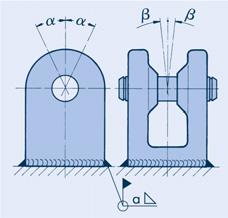
Energy absorber
type 32 18 16 to 32 92 16
Serial standard design.
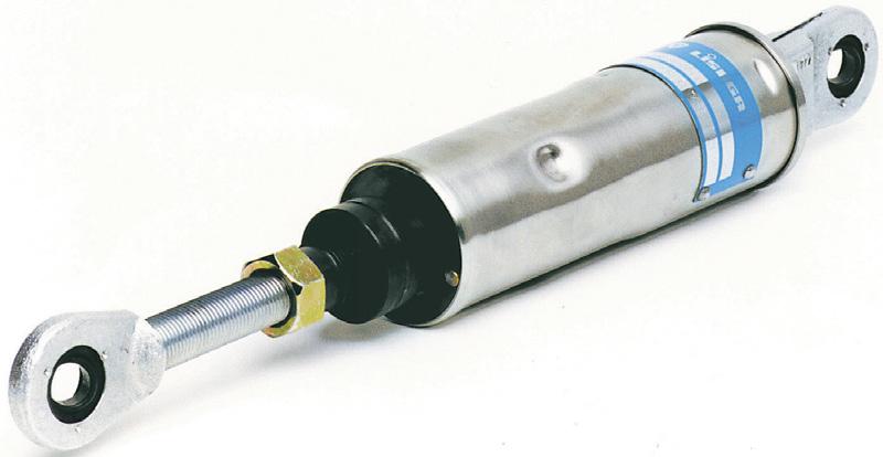
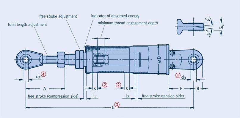
If the nominal load is exceeded, the increasing force and displacement are transformed into deformation energy.
Max. deformation travel in compression and tension directions.
‘E’ dimensions on middle position of the free strokes t1/t2 and length adjustment ‘A’ dimension. If t2 changes, the ‘E’ dimension is correspondingly reduced or increased.
Connection possibilities: see pin diameters of weld-on brackets Type 35 or dynamic clamps in Product Group 3.
Order details:
energy absorber
type 32 .. 16
t1 = …mm, t2 = …mm marking: ...
The standard designs shown in the table above represents only part of the suppliable range. The products can be adapted by LISEGA to the particular requirements of the user.
This applies especially to those cases where loads and strokes exceed standard parameters.
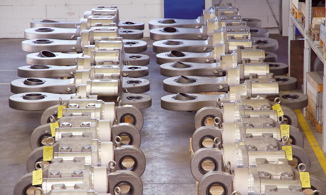
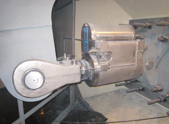
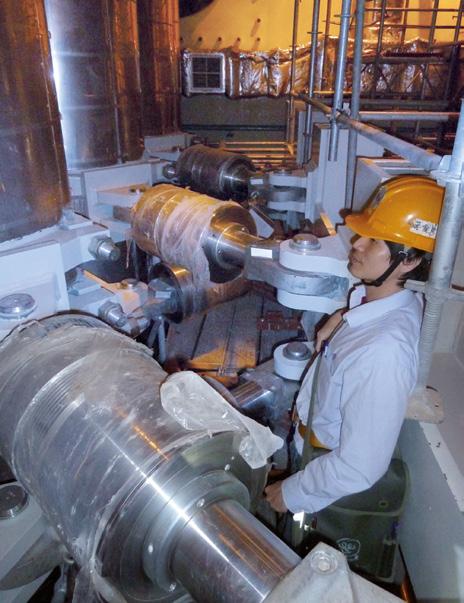
Viscoelastic damper type 3D 03 44-D to 3D H1 44-D
When selecting viscoelastic dampers attention should be paid to the temperature existing on site. These dampers are available for application temperatures ranging from 20°C to 80°C, whereby the various damping media cover a temperature range of 10°C in each case. For this reason the correct selection of application temperature is important.
The choice of damper size depends on the nominal load. The offset in horizontal and vertical directions must be considered for the cold load position. For LISEGA dampers in the 44-D series this amounts in each case to 40mm in horizontal/ vertical directions.
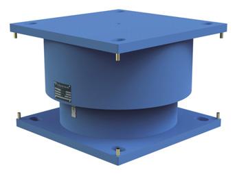
= working range round the mid-position
Further information about vibration reducing products are to be taken from the product catalogue VICODA.
Inner thread for transport ring screw.
Order details: viscoelastic damper type 3D .. 44-D marking: … nominal load: …kN offset: … x: …mm, y: …mm, z: …mm operating temperature: …°C
The operation of the dampers should be in the center position. In order to achieve the necessary damping resistance, the viscous dampers should not exceed a tolerance of 20 mm from the center position in any operating condition. Before any start-up the dampers require preheating at operating temperature.
load range: 2.5kN up to 100kN frequency range: up to 35Hz temperature range: 20°C up to 80°C (in 10°C stages)
offset (cold position) to mid-position: up to 40mm (horizontal/vertical)
The table values are minimum values at ordered working temperature. At lower temperatures the damping resistance increases. If required, the equivalent stiffness (kN/mm) can be given in vertical and horizontal directions.
3D 03 44-D2.524027021583414–16
3D 05 44-D524029023083414–19
3D 10 44-D10240340270103818M1631
3D 20 44-D20280390320124222M1651
3D 30 44-D30320440350154626M1684
3D 40 44-D40335470380184626M16109
3D 60 44-D60350510410205333M16149
3D 80 44-D80390535430255939M16191 3D H1 44-D100405580460305939M16246
3D
3D 20 44-D2089.367.957.951.647.344.041.494.072.557.847.540.636.334.2
3D 30 44-D30143.9109.493.283.276.270.966.7148.7114.591.575.164.257.454.1
3D
3D
3D
3D
When selecting viscoelastic dampers the temperature on site is important. Series 3D .. ..-L is designed for use in a temperature range from -10°C up to +40°C. In this temperature range the damper functions with relatively constant characteristics. The values were determined for a temperature of 20°C.
The choice of damper size depends on the nominal load. The offset in horizontal and vertical directions must be taken into account for the cold load position. For LISEGA dampers in the 33-L and 55-L series it amounts to 30mm and 50mm respectively in horizontal / vertical directions.
The operation of the dampers should be in the center position. In order to achieve the necessary damping resistance, the viscous dampers should not exceed a tolerance of 20 mm from the center position in any operating condition. The dampers do not need to be preheated to operating temperature before start-up.
The table values are minimum values at 20°C. At lower temperatures the damping resistance increases. If required, the equivalent stiffness (kN/mm) can be given in vertical and horizontal directions.
Viscoelastic dampers type 3D 05 33-L to 3D 50 55-L
load range: 2.5 kN up to 50 kN frequency range: up to 35 Hz temperature range: – 10°C up to + 40°C offset (cold position) to mid-position: up to 30 mm (type 3D .. 33-L) up to 50 mm (type 3D .. 55-L) (horizontal/vertical)
= working range round the mid-position
Further information about vibration reducing products are to be taken from the product catalogue VICODA.
Inner thread for transport ring bolt
Order details: viscoelastic damper type 3D .. ..−L marking: … nominal load: …kN offset: … x: …mm, y: …mm z: …mm operating temperature: …°C
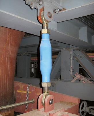
When selecting rigid struts from the below tables, these points must be noted:
1. The specified operating load must be covered by the nominal load.
2. The load group is determined at the same time by the nominal load.
3. The adjustment range available for the rigid struts is given for the specified installation length.
4. The weight is specified at the intersection between load group and adjustment range. If the intersection lies below the red boundary line, it is a matter of an extended length with reduced load that must be checked in the diagram on page 3.28 for agreement with the specified operating load.
5. When ordering, the type designation is to be completed at the 3rd digit by entering the load group number.
39
39 .2 041850 - 21502000(6.6)
39
39
39 .3 042850 - 31503000
39 .3 243100 - 34003250 (21)(28)53
39 .3 543350 - 36503500 (23)(30)5789144
39 .3 743600 - 39003750 (31)619515439
39 .4 043850
39
reduced loads for overlength (below red line) see diagram on page 3.28
slenderness ratio 150, for greater lengths the slenderness ratio can range between
150 and 200; the weight of these rigid struts is given in brackets.
The type designation is to be completed in the 3rd digit with the load group.
39
Rigid struts type 39 20 32 to 39 06 03
The diagram on the left shows the reduced load values against nominal load that must be taken into account for extended lengths.
Material: body P235GH P355NH ball P250GH bushing C45E+QT joint S355J2 42CrMo4+QT
An exceeding of the maximum lateral displacement of 6° is to avoid.
Minimum thread engagement depth on the ball bushing joint marked by an undercut.
Ball bushing width.
The type designation is to be completed by the length index (4th and 5th or 4th to 6th digits in the type designation, page 3.27).
Due to their design, the rigid struts have freely variable adjustment, with right-hand / left-hand threads, similar to a turnbuckle. Shorter installation lengths for rigid struts are possible as special designs.
Connection possibilities: see pin diameters of weld-on brackets type 35 or dynamic clamps type 36 / 37 in product group 3.
(…) Values in brackets: up to Emax = 650mm.
Depending on load group and length the rigid struts are subject to alternative manufacturing technologies which may result in designs different to the shown.
Order details: rigid strut type 39 .. ..
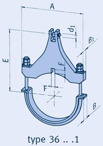
Calculation of intermediate values: linear interpolation.
The connection load group is to be specified when ordering. On selection of a smaller load group than that shown in the table, the ‘E’ dimensions of the clamp are reduced (see table on page 3.15). Fit: H7 f8.
Shear lug dimensions: F minus 1mm; B1 plus 2mm (see page 3.44).
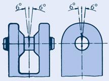
108.0
OD 114.3 (ND 100)
Calculation of intermediate values: linear interpolation.
The connection load group is to be specified when ordering. On selection of a smaller load group than that shown in the table, the ‘E’ dimensions of the clamp are reduced (see table on page 3.15). Fit: H7 f8. Shear lug dimensions: F minus 1mm; B1 plus 2mm (see page 3.44).
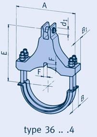
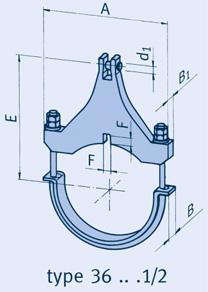
Calculation of intermediate values: linear interpolation. The connection load group is to be specified when ordering. On selection of a smaller load group than that shown in the table, the ‘E’ dimensions of the clamp are reduced (see table on page 3.15). Fit: H7 f8.
36
36
Calculation of intermediate values: linear interpolation.
The connection load group is to be specified when ordering. On selection of a smaller load group than that shown in the table, the ‘E’ dimensions of the clamp are reduced (see table on page 3.15). Fit: H7 f8. Shear lug dimensions:
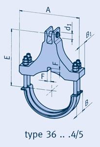
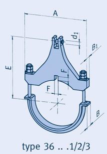
Calculation of intermediate values: linear interpolation.
The connection load group is to be specified when ordering. On selection of a smaller load group than that shown in the table, the ‘E’ dimensions of the clamp are reduced (see table on page 3.15). Fit: H7 f8. Shear lug dimensions: F minus 1mm; B1 plus 2mm (see page 3.44).
36
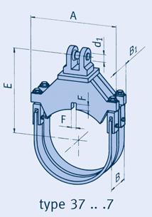
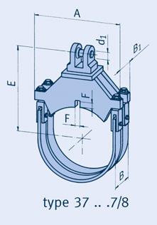
Calculation of intermediate values: linear interpolation.
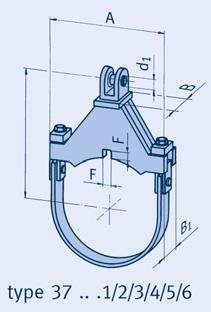
Calculation of intermediate values: linear
The connection load group is to be specified when ordering. On selection of a smaller load group than that shown in the table, the ‘E’ dimensions of the clamp are reduced (see table on page 3.15). Fit: H7 f8.
dimensions:
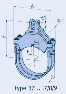
Calculation of intermediate values: linear interpolation.
The connection load group is to be specified when ordering. On selection of a smaller load group than that shown in the table, the ‘E’ dimensions of the clamp are reduced (see table on page 3.15). Fit: H7 f8.
Shear lug dimensions: F minus 1mm; B1 plus 2mm (see page 3.44).
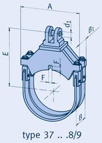
Calculation of intermediate values: linear interpolation.
The connection load group is to be specified when ordering. On selection of a smaller load group than that shown in the table, the ‘E’ dimensions of the clamp are reduced (see table on page 3.15). Fit: H7 f8.
Shear lug dimensions: F minus 1mm; B1 plus 2mm (see page 3.44).
Calculation of intermediate values: linear interpolation.
The connection load group is to be specified when ordering. On selection of a smaller load group than that shown in the table, the ‘E’ dimensions of the clamp are reduced (see table on page 3.15). Fit: H7 f8.
Shear lug dimensions: F minus 1mm; B1 plus 2mm (see page 3.44).
37 T2 31 52514833 30950119014512016 6 86
37 T2 32 80797652 30950121518014616
Calculation of intermediate values: linear interpolation.
The connection load group is to be specified when ordering. On selection of a smaller load group than that shown in the table, the ‘E’ dimensions of the clamp are reduced (see table on page 3.15).
H7 f8.
Shear lug dimensions: F minus 1mm; B1 plus 2mm (see page 3.44).
Calculation of intermediate values: linear interpolation.
The connection load group is to be specified when ordering. On selection of a smaller load group than that shown in the table, the ‘E’ dimensions of the clamp are reduced (see table on page 3.15). Fit: H7 f8.
Shear lug dimensions: F minus 1mm; B1 plus 2mm (see page 3.44).
The shear lugs secure the position of the dynamic clamps in the expected direction of force and are practically unstressed. Even in a load case, friction forces from the pipe-clamp-contact ensure firm positioning. Lateral forces are negligable.
Due to the minimal forces to be absorbed, the weld seam stresses can be kept at a low level, despite the small dimensions of the shear lugs. As a rule they lie under 35% of the yield strength or creep stress limit for load case H (level A/B) according to the permissible ASME or EN values.
The selection of suitable shear lugs is made after selection of the dynamic clamp and the corresponding dimensions F and B1 according to the selection tables of dynamic clamps on pages 3.29 – 3.43
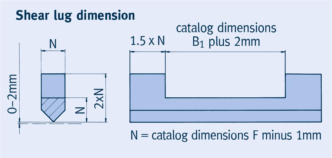
The specified materials for the shear lugs are materials delivered from stock and delivered at short notice. The customer is responsible for the suitability of the pipe material on hand and for the weld seam sizes.
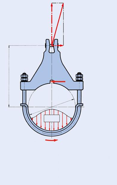
3rd – 6th digits of pipe clamps – 0316Mo3 type numbers e.g.: 36 22 31 – 0413CrMo4-5 2231 – 0510CrMo9-10
Different materials on request.
For shear lug on a pipe clamp type 36 22 31 for a pipe made from material 13CrMo4-5: Order number 3L 22 31-04
To secure dynamic clamps type 36/37 against misalignment due to compressive stress and off-axis load applications, LISEGA offers standardized shear lugs.
Order details: shear lug type 3L ..
Snubbers are precision components of crucial importance for safety. Correspondingly, great care must be taken when dealing with them. Attention to the following points in these instructions is the prerequisite for their proper functioning.
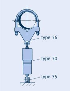
Typical installation situation for type 30
name plate
piston rod cover sight glass travel indicator
connecting lug
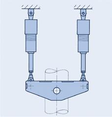
and
LISEGA snubbers are high-precision components of great relevance for safety that must be treated with special care during transport, storage, unpacking and handling before and after installation. At this the temperatures should not fall below – 20°C.
Snubbers and their ancillary components must be stored in enclosed spaces. They must be protected from dirt and damage. It is recommended that they should be left in their original packaging until installation. Any transport damage incurred or damage caused during their handling on installation must be reported at once to the manufacturer.
Snubbers are not suitable in any way as substitutes for steps or ladders. Before work such as sand blasting, welding, painting etc. is carried out in the close vicinity of a snubber, the snubber must be dismantled, removed and protected.
The snubbers are supplied as fully operational components including hydraulic fluid. On type 30 the connecting lugs are bolted on one side to the base of the snubber and on the other to the piston rod and secured with clamping bolts.
LISEGA snubbers are manufactured entirely of corrosion resistant materials. They therefore require no additional surface treatment. The threaded connecting lugs are electro galvanized and white chromatized.
Weld-on brackets type 35 are supplied separately with the appropriate pins. The surface protection hereby consists of a weldable primer.
For shipment the type 30 snubbers are packed singly with retracted pistons in suitable crates.
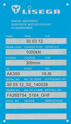
Stamped on the name plate are:
type designation nominal load theoretical stroke oil type and volume
serial number
order number
marking and ident. number, if required
The snubbers must be inspected for damage before installation. It must also be ensured that the connecting lugs are firmly attached. The connection components on site and the connecting brackets must be fully welded.
The arrangement of the connection brackets must always be selected so that the maximum deflection angle is in the direction of the greatest operational heat expansion. The lateral displacement is restricted to a maximum of 6°. Misalignment of the connection brackets should be prevented, due to the limited possibility of movement.
Any welding at the connections or in their vicinity should take place before installation of the snubbers.
For installation, the type 30 snubbers are to be brought to the required installation dimension (dimension from connection pin to connection pin) by extending the piston rods to the necessary installation dimension.
To avoid undesirable blockage of the snubber the rods must be extended slowly, smoothly and below lock-up velocity. The piston rod of the smaller snubbers can be shifted manually. The dead weight of the large-bore snubbers can also be utilized by suspending the snubber from the connecting lug of the piston rod.
The snubbers can be installed in any orientation. The piston rod should be connected to the heat-conducting component so that any radiated heat can be dissipated through the protective cover. When a snubber installation extension is used, the extension should be connected to the heat source.
The snubbers should be installed in such way that the sight glasses for fluid checks are easily visible from the maintenance walkway.
The connection to the connecting structures must be force- and form-locked. Bolted connections, which are in the flow of force must have sufficiently high pretension.
If after installation of the snubber welding work on the connections has to be carried out, care must be taken that no welding current passes through the snubber.
After assembly of a complete system the subsequent inspection of every point of application is recommended:
A. Inspection of all connection points for forceand form-fitting attachment (locking- bolts on the connection lugs, securing of pins, boltings at connections).
B. Inspection of the installation position for freedom of movement on expansion. Care must be taken that the connection lugs in the connection brackets remain freely movable and that the piston cannot run into the end of snubber travel.
A travel reserve of min. 10 mm at the end positions is recommended for the piston position. The position can be read off the travel indicator.
Before commissioning of the plant a final visual inspection of all snubbers and their installation positions is recommended.
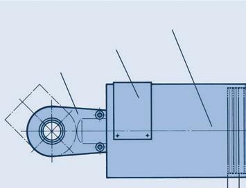

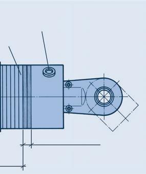
Under normal operating conditions the snubbers are designed to function trouble-free for the maximum lifespan of a plant. To maintain the operating capacity of the snubbers at all times preventive maintenance is recommended. For this, see page 3.47, ‘Maintenance recommendations’.
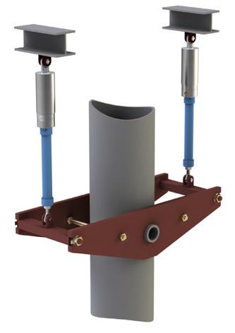
Restraint of a vertical pipe system section by type 30 snubbers with installation extension type 33 and dynamic clamp type 34.
Snubbers are crucially important components for the safety of a plant. They serve to protect the piping systems and other components from dynamic overloading from unplanned load cases. As these events occur unpredictably, the full functional safety of the snubbers at all times must be guaranteed.
Under normal operating conditions the service life of the snubbers is designed to match the maximum operational life (60 years) of a plant. The seals and hydraulic fluid should be exchanged at least once during this period, at the latest after 23 years.
Under certain conditions of use (extreme loading), premature aging or increased mechanical wear cannot be excluded. In accordance with the stringent demands concerning reliability, preventive maintenance is recommended. The performance of maintenance work is the responsibility of the plant operator.
1. Regular inspection –Visual inspection once a year
2. Extended testing –Function test, at the latest after 12 years of operation
Implementation
The inspection and maintenance work must be carried out by specially trained personnel.
If required, this work can be performed by specially trained LISEGA service technicians. Fully certified testing facilities are available for dynamic function tests – these mobile test benches can be brought to the plant.
The regular inspection consists of a visual check and should be carried out once a year on all components installed. The first inspection should be directly before commissioning.
In the course of this inspection not only the snubbers but also the installation situation and surrounding conditions must be controlled. The procedure should be carried out with a checklist containing the following information:
all positions to be inspected, with details of their locations.
planned, operation-related displacements in connections special ambient or operational conditions maintenance measures previously carried out
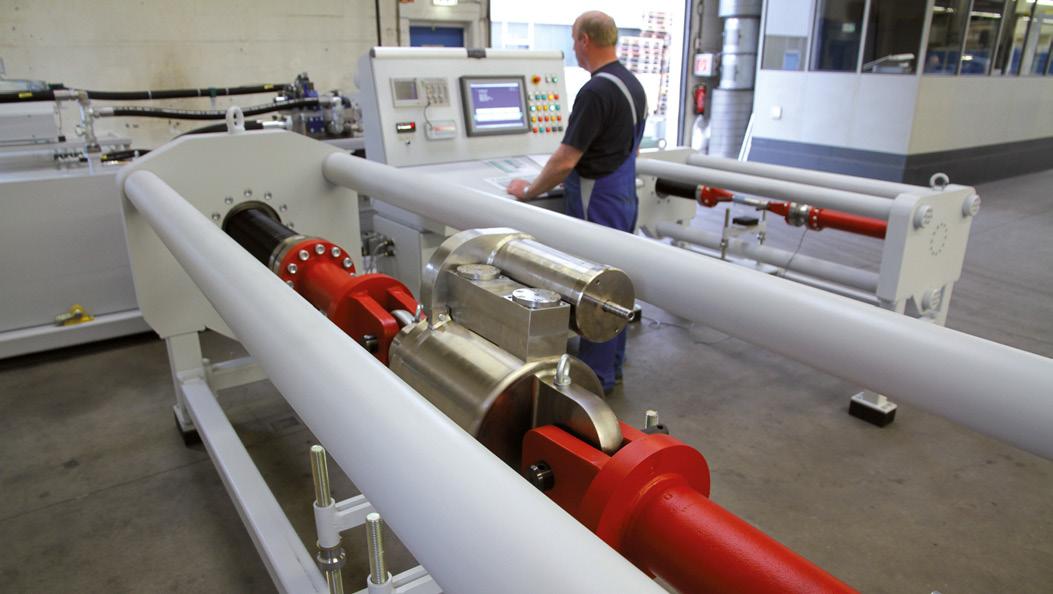
The following points are to be checked at the installation position:
name plate data, for conformity with check list connections at attachment points for force-fitting freedom of movement for the snubbers on operational deflections position of piston rod for sufficient stroke, incl. travel reserve (min. 10mm) external condition for possible signs of damage or leakage immediate surroundings for any indications of unusual operational stresses, e.g. increased temperature inspection glass for fluid level
As long as the reservoir piston is not visible in inspection glass there is sufficient fluid reserve in the reservoir. If the reservoir piston is visible a leakage of fluid must be assumed.
Observations and conclusions must be recorded on the checklist and if necessary supplemented by recommendations for corrective measures.
A supplementary inspection is carried out after an operational period of 12 years in which a small selection of the snubbers installed (min. 2 units per type) are subjected to an additional function test.
After successful testing the snubbers can be re-installed. If any anomalies in behavior are noted, the components in question should be dismantled and the condition of the functionally important individual units examined. The plant management is responsible for any necessary corrective measures and for their documentation.
The scope of the inspections and the selection of the snubbers to be tested should be agreed on between the plant management and the service engineer involved. The different forms of stress (temperature, radiation, loads, operational vibrations) should receive particular attention.
The time-point and scope of the next extended inspection is to be determined on the basis of the recorded test findings.
It is recommended that, after 23 years of operation at the latest, the seals and hydraulic fluid should be exchanged. After the professional execution of this work, the use of original LISEGA spare parts, and successful function testing, the snubbers can go into operation for a further 23 years.
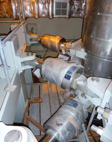
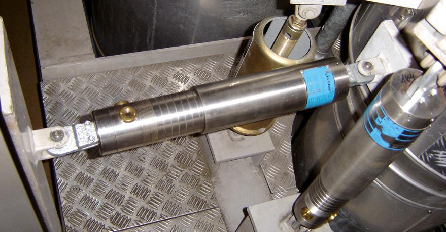
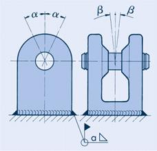
LISEGA weld-on brackets type 35 are supplied painted and with fitted pins. The surface protection typically consists of a weldable primer, unless otherwise noted.
The connection components and connecting brackets on site must be fully welded.
1. Remove pins from weld-on bracket.
2. Preheat weld-on bracket from type 35 79 19 and above to appr. 100°C.
3. Use base electrodes.
4. Apply the weld seam in layers to avoid welding distortion (Welding sequence: see below).
5. Allow the weld-on bracket to cool down to 100°C after every layer.
35 19 133.03.03.0
35 29 133.03.03.0
35 39 133.03.03.0
35 49 133.04.05.0
35 59 195.57.08.0
35 69 197.59.511.0
35 79 1910.513.515.5
35 89 1914.518.021.0
35 99 1115.020.023.0
35 09 1314.017.019.0
35 20 1923.0––
Explanation of weld seam symbols: = in mm
The arrangement of the weld-on brackets should always be so arranged that the max. angulation is in the direction of the operational thermal expansion . The lateral displacement is restricted to max. 6° . Any misalignment of the weld-on brackets should be prevented due to the hereby limited freedom of movement.
Welding at the connecting components or in their immediate vicinity should be carried out before installation of the snubbers, rigid struts, etc.
The following procedure is recommended for the welding of the brackets:
The minimum weld seam thickness ‘ ’ for weldon brackets type 35 depends on the angulations and . In the calculation a permissible stress of 90N/mm2 in load case H (level A/B) was the basis.
On an increase in the angulation to 90° the permissible stresses are reduced by approx. 15% at constant weld seam thickness (a min. at = 45°).
The relevant load table (“technical specifications” page 0.6) applies for the permissible stresses.
Schweißfolge Typ 35
Note: Welding must be carried out only by qualified personnel and is to be supervised by the technical department. When mounted vertically, vertical welds should be made in upwards direction.
After completion of the attachment, the primer surface of the weld-on brackets can be painted. It is urgently advised to do this before installation of the snubber.
Care must be taken during transport that the viscoelastic damper type 3D is always in upright position to avoid any leakage of the damping medium. When storing in the open the dampers are to be protected from dirt and water.
LISEGA viscoelastic dampers are delivered preset to cold condition (offset). This is ensured by the transport brackets, which keep the offset position fixed in place between the upper and lower sections of the damper. If not ordered otherwise the blocking position (offset position x = 0, y = 0, z = 0) is supplied.
For a weight greater than 20kg, an M16 inner thread of limited engagement depth is located in the upper connection plate for attachment to a hoist.
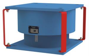
lower connection plate casing position indicator transport bracket upper connection plate connection thread M16 for hoist name plate
The following information is stamped on the name plate:
type
serial and commission number
nominal load
operating temperature ident. number
For installation, attention must be paid to the requirements of the installation instructions for the pipe systems. The LISEGA viscoelastic damper, which is supplied with installation load (cold load) is transported to the place of assembly in an upright position. A force-fitting connection of the upper and lower connection plates is made to the pipe system and steelwork. For this, the transport brackets must be removed. The bolt torque values can be found in the table at the side.
For types 3D.. ..-D it is recommended that the plant should be started up slowly so that the dampers can adjust to operating temperatures, otherwise strong reaction forces could develop that exceed the specified nominal loads. If required, the dampers could be brought to operational temperature by means of supplementary heating. During commissioning the relative position of the upper and lower connection plates changes to hot load position, as calculated beforehand.
During operation the damper should function roughly in middle position, otherwise the dynamic characteristics of the damper change. If the middle position in the tolerance range is not reached the calculations are to be reviewed.
LISEGA viscoelastic dampers are in principle free of maintenance, but an annual visual inspection is recommended. For revision purposes the transport brackets can be attached again.
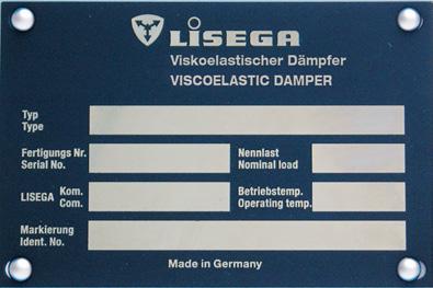
* Values according to VDI 2230 Appendix A, friction value µ = 0.14
= Working range of
at the middle position
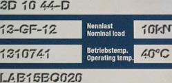
Care must be taken that the dynamic clamps are not damaged during transport. It is recommended that the components are only stored in dry, enclosed spaces. If storage in the open is unavoidable, the clamps must be protected from dirt and water.
LISEGA dynamic clamps are supplied with all the necessary boltings for installation. For reasons of dispatch optimization the clamps may be delivered partially assembled.
In order to avoid any kind of twist of the clamp it is recommended that shear lugs be fitted. See also page 3.44.
The dimensions of the recesses for the shear lugs can be found in the selection tables for dynamic clamps on pages 3.29 – 3.43.
This design consists of a massive upper section with integrated connecting bracket and, depending on the load range, with one or two U-bolts and a shim plate.
For installation the pre-assembled U-bolts must be removed. The upper part, fitted with a lug recess, is seated on the shear lug. The U-bolt is inserted from the opposite side together with the shim plate and at first only loosely screwed. The position of the clamp is to be checked again for proper alignment. The bolts can then be tightened and locked.
This design is the heavy duty version for large pipe diameters and heavy loads.
As a rule, type 35, the weld-on bracket suitable for the load, is already welded on. If the bracket is delivered separately at customer request, the welding instructions on page 3.49 are to be followed when welding.
The counterpart to the upper section of the clamp consists, depending on the load, of one or two flat steel straps which are connected by pins to the upper section for transport.
For installation the flat steel straps must be removed by loosening the pin connections. The upper part with the lug recess is seated on the shear lug. From the opposite side the flat steel strap is inserted into the bolt-on clevis and fastened with the pins, which are then locked with splints.
The position of the clamp must be checked once again for proper alignment. The bolts can then be firmly tightened. To avoid unintentional loosening the hexagon nuts on the bolts must be locked with tab washers.
ProducT 4 grouP
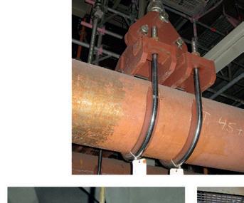
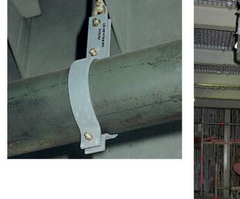
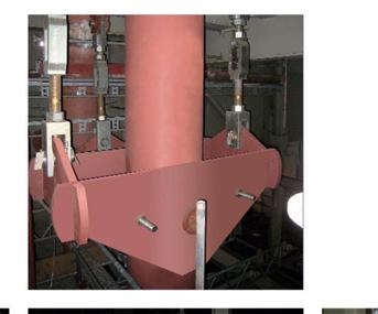
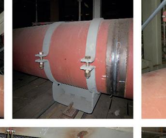
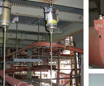
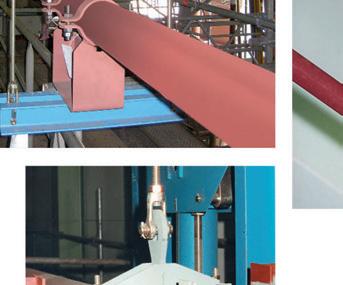
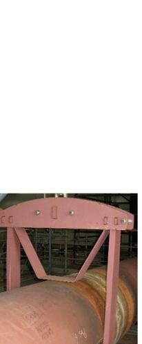
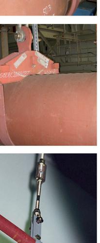
In high temperature pipe systems, pipe clamps and clamp bases are the most highly stressed and hence the most vulnerable components in the support chain due to the effects of such high temperatures. However, pipe clamps are seldom checked, as access is difficult after commissioning due to the surrounding insulation.
Pipe clamps, clamp bases, pipe weld-on lugs and U-bolts all fall into the category of pipe connections. For these products, the design criteria of the pipe systems lead to wide variations, and so to a particularly large number of components. The dynamic clamps of product group 3 also belong in principle to this group. The design of both horizontal and vertical piping is determined by:
diameters loads
temperature of the medium insulation thicknesses
For proper coverage of the whole spectrum with safe components, LISEGA provides a complete program of standardized products for the whole field of application.
Following the special requirements of this field, the corresponding ideal design has been developed.
Diameters range from OD 21.3 to OD 1219, the temperature range extends to 650°C and
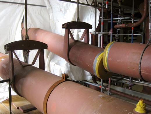
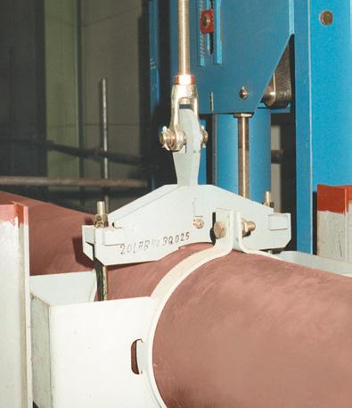
the permissible loads – divided into economical areas of operation – cover the highest level of the practical field of application.
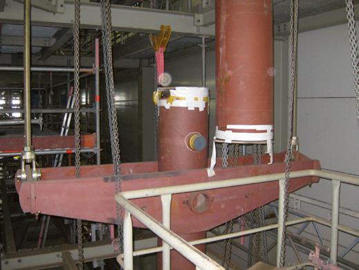
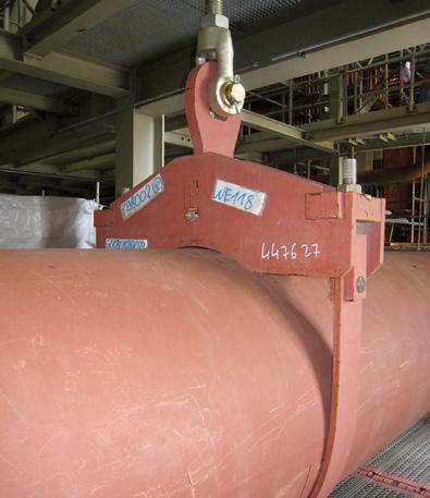
These standardized components form an integral part of the LISEGA modular system, so load and connection compatibility are correspondingly assured.
Because of their critical field of application the design and construction of the pipe-surrounding components require special attention.
As a matter of principle, just as much care and attention should be given to the pipe supports as to the piping itself, since the pipe systems can never be better than their supports!
The most important prerequisite for reliable component quality is comprehensive standardization.
When choosing suitable products the customer should therefore place his confidence in components of proven quality.
Plant designers, constructors and operators can all benefit from the standardization of the whole spectrum of application with state-ofthe-art design:
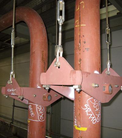
complete and clearly structured data tables simplify planning
all supplies from a single source through integration into a comprehensive support program (LISEGA modular system)
superior quality at competitive prices through rational series production and technically advanced designs
consistent standardization enables short lead times
favorable performance / weight ratios, easy-to-install designs and connection compatibility of LISEGA components allow efficient installation
design in accordance with current codes ensures maximum operational safety
heat loss reduced through compact component dimensions
certifications by independent testing institutes can be supplied
for pipe clamps used at higher temperature ranges, materials certified according to EN 10204-3.1 are used
1 Weld-on lug type 41
This type is mainly used as a pipe connection for pipe systems under 80°C on horizontal pipes or pipe elbows.
2.1 Horizontal clamp type 42 .. 17
This clamp can be used as a construction clamp or hanger clamp in cold piping systems. The field of application is limited to smaller pipe dimensions.
2.2 Horizontal clamp type 42 .. .9
This clamp is used for larger pipe dimensions.
3 Horizontal clamp type 43
This hanger clamp follows the traditional flat steel design. Its use is limited to an economical range up to an individual weight of approximately 25kg. Connection to the load chain is made by pin and LISEGA threaded eye nuts type 60.
The application range of the pipe clamps can extend over several LISEGA load groups due to the interdependency of load and temperature in material properties. For this, the eye nuts are so designed that at least three corresponding pin diameters can be accommodated.
4 Horizontal clamp type 44
A rigid yoke takes up the load from a pipesurrounding U-bolt with a shim plate. From certain diameters, temperatures or load ranges, a flat steel strap is used instead of a round steel U-bolt.
Completely eliminating welds, the individual components are form-fitted with plug connections and bolted to each other (Patent No. DE 3817059).
Horizontal clamp type 44 is used where type 43 reaches economic limits. These are essentially the high temperature, large pipe diameters in high load ranges.
Connection to the load chain is made with a lug and LISEGA clevis type 61. The connection lug is designed to accommodate connection pins in a number of LISEGA load groups.
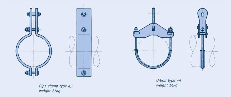
With the riser clamp type 45 the lower load and temperature ranges are covered. This design is particularly economical for its diameter range.
Connection to the vertical piping is made with shear lugs welded to the pipe. The design and fitting of the lugs is the responsibility of the piping manufacturer.
Connection to the load chain is made with pins and LISEGA threaded eye nuts type 60. At least 3 LISEGA load groups can be covered.
When ordering, the span required (dimension L) must be specified.
The design of this riser clamp uses the box shape for its economical use of material.
The individual parts are connected without welding by means of connections, then locked to each other (Patent No. DE 3817015).
Connection to the vertically arranged pipe system can be made in two different ways and so requires two different designs:
Type 46, for load support using 4 shear lugs welded to the pipe. Two lugs are in general used only for ND 150 and must be so arranged that they are located directly above the side section.
Type 48, for load support using trunnions welded to the pipe.
The bore hole diameter for trunnions amounts to approximately 1/3 of the pipe diameter in accordance with ASME Code Case N3923 and DIN EN 13480-3.
Connection to the load chain is done with integrated lugs designed for connection to LISEGA threaded clevises type 61.
The connecting lugs are shaped in such a way that they can accommodate the connection pins for several LISEGA load groups.
The inner dimensions of the box, which are required for the later trunnion calculations (N dimension) can, depending on the pipe diameter OD, be taken from the table at the bottom right.
Materials of pipe clamps and clamp bases
clamp type 46 with connections
clamp type 48 with connections
Inner width of box (N-dim.) of riser clamps type 46/48
Clamp bases are generally used as slide bearings (loose supports) for horizontally arranged pipe systems.
As with pipe clamps, the application spectrum covers a diameter range from OD 21.3 to OD 1219 and a temperature range up to 600°C; for OD up to 88.9: 650°C.
In addition to the support load, the operating temperature of the pipe system is an essential criterion in the design of clamp bases; the material to be used is determined by this. The installation height is governed by the thickness of the insulation.
Fixed installation heights are assigned to the temperature ranges in order to keep the number of sizes within a reasonable range.
The fixed installation heights relate, for all diameters, to the respective lower rim of the pipe and change by 50mm or 100mm increments.
The standard dimensions selected for the support height of the pipes, as well as the length of the slide bases, cover the majority of applications.
Different applications, according to temperature and loads, require different clamp base designs.
If required, components with special dimensions can be supplied. A small selection is shown on page 4.9 in the section ‘Special designs’.
Possible load applications on a clamp base.
µ = friction coefficient
Further information on page 7.11.
The design (version 1) for this field of application consists of two omega-shaped halves. On installation with the piping the lower section is firmly bolted and forms the slide base.
In the upper section the pipe is held in position by bolting.
Through the free space under the pipe gained by the design (version 1) of the component, constant ventilation of this area is ensured. This is essential for cold pipe systems, as otherwise pipe corrosion caused by moisture could result after only a short time. These clamp bases are electro galvanized as a standard.
This design (version 2) consists of a shaped lower metal plate, firmly welded to two pipe clamps. The lower section is fitted, according to the respective design load, with a reinforcing gusset.
These clamp bases can be used in a variety of ways. By using two lower sections set against each other, a double guide can be easily produced (Fig. 2). By additionally
Examples of use:
(Fig. 1)
fitting lateral guides, guidance from all sides can be provided.
The shape of the base plate permits the simple mounting of lift-off restraints (Fig. 1). The lower section is so designed that it can be fitted with a stainless steel plate as a sliding surface for a slide component. See also ‘product supplements’, page 4.7.
If required, special lengths or heights are possible. For very large expansion displacement it might be more expedient to arrange for correspondingly long support surfaces on site.
For special pipe diameters not contained in the selection tables, either corresponding intermediate sizes are supplied, or suitable inlay plates are provided for slight diameter differences.
If required, double or multiple guides on the basis of standard clamp bases can be supplied. See also page 4.8.
(Fig. 2)
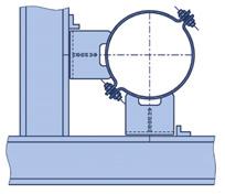
Pipe clamps and clamp bases are often equipped with supplementary parts for special applications. For this purpose LISEGA offers a wide variety of possibilities.
For the support of austenitic pipe systems, all LISEGA pipe clamps and clamp bases can be fitted with stainless steel inlay plates of the material 1.4301 (X5CrNi18-10). These plates must be ordered separately and are offered with the following type numbers:
For type series 36: Stainless steel plate 36 .. ..-IP
For type series 37: Stainless steel plate 37 .. ..-IP
For type series 42: Stainless steel plate 42 .. 09-IP
For type series 43: Stainless steel plate 43 .. ..-IP
For type series 44: Stainless steel plate 44 .. ..-IP
For type series 45: Stainless steel plate 45 .. ..-IP
For type series 46/48: Stainl.st.plate 46/48 .. ..-IP
For type series 49 .. 11/12:
Stainless steel plate 49 .. .. -IP
For type series 49 .. 13/14/25/35/45/55:
Stainless steel plate 2x 42 .. 09-IP
Examples: For a pipe clamp type 44 27 13 inlay plate type 44 27 13-IP. For a clamp base type 49 11 25 2 x inlay plate type 42 11 09-IP.
Material thickness: 0.5mm
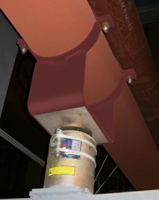
To reduce friction resistance in clamp bases, all of them can be fitted with stainless steel sliding surfaces of the material 1.4301 (X5CrNi18-10). These sliding surfaces, in combination with PTFE slide plates type 70 (up to 180°C) or the new LISEGA high temperature sliding material (up to 350°C), reduce friction forces by approx. 10 – 20% of the support load. See also section ‘slide plates’ page 7.10
This version of the clamp bases with slide plates must be ordered separately. For this, please add the type number suffix “SP”:
Examples: 49 22 14-SP 49 27 14G2A-SP
The installation height of the clamp base increases by approximately 3mm.
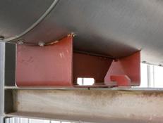
The clamp bases can if required be fitted with lift-off restraints. These restraints ensure that the clamp base remains in position if the support load is too small or the clamp base cannot be welded on. They can be ordered according to the selection tables (page 4.68).
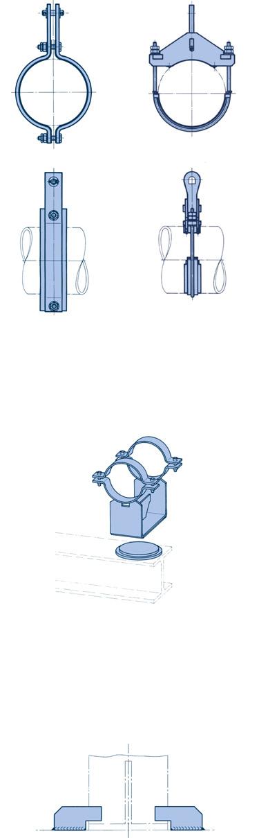
Two pipe clamps types 43 and 44 can be coupled with connection plates. This way the load can be doubled. A selection is shown on page 4.67.
When ordering, this is made clear by replacing the type designation of the clamps with “77”.
Example type 43:
77 09 39 for clamps 43 01 19 – 43 09 59
77 17 39 for clamps 43 10 19 – 43 17 59
77 19 39 for clamps 43 19 19 – 43 19 59
Example type 44:
77 66 38 for type 44 66 38
The load group must be specified for type 44, as the upper connection (type 60) must be correspondingly selected.
Separating tapes are used when the pairing of dissimilar materials in pipe and pipe supports must be electrically separated to prevent local corrosion. This way, the piping can be fitted with supports of more economical martensitic materials, and still be more effectively protected.
The adhesive separating tapes can be applied in a temperature range from –35°C to +210°C and are largely resistant to acids, bases and solvents. They are applied as adhesive tape (in part multilayered) to the grease-free piping at the point where the pipe clamp body surrounds the pipe. The material thickness amounts to only 0.5mm.
The tapes are supplied in different widths to suit the clamps in whole meter lengths. The order designation is:
It is often necessary to limit the piping in its displacement horizontally, vertically or in both directions. On the basis of the type 49 standard designs (version 2), pipe guides are offered here as a variant corresponding to the standard design in form and load capacity. The order number is made up from the standard type number and the desired features of the design.
Example:
type 49 standard: 49 .. .. type 49 double guide parallel: 49 .. .. G2P type 49 lateral guide angulated: 49 .. .. G2A type 49 triple lateral guide: 49 .. .. G3 type 49 foursided guide: 49 .. .. G4
These designs can be fitted with extra slide plates.
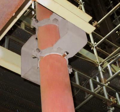
42 00 04b=4042 00 11b=110
42 00 05b=5042 00 12b=120
42 00 06b=6042 00 15b=150
42 00 07b=7042 00 17b=170
42 00 08b=8042 00 20b=200
42 00 09b=9042 00 22b=220
42 00 10b=100
Order details: Anti-corrosion separating tape type 42 00 .. L = …m
For pipe supports, the application of standardized components has long since proven itself through enormous savings in time and costs where design, shipment and installation are concerned. This applies particularly to pipe clamps and clamp bases.
However, the general complexity of pipe systems requires an extremely wide range of applications for these components, which in special cases demands the use of special designs. For the technically correct solution it is necessary in such cases to rely on experienced professionals, who can offer triedand-tested solutions and calculation processes.
The standardized LISEGA program of pipesurrounding support components is comprehensive and covers all general cases of applications, going well beyond the usual spectrum in this field. In spite of this, more complicated cases sometimes occur where only a special design can provide the best solution. Among other things, special designs are most often called for in the following situations:
unusually restricted spaces avoidance of interferences custom-made anchors exceptionally high load requirements special pipe diameters especially high temperatures (up to 1000°C) larger insulation thicknesses unusual angles in piping special trunnion diameters twist restraints / shear lugs
LISEGA’s customers are not left alone in such situations. For these special problem cases, an experienced team of technicians and engineers is on hand, ready to react rapidly and flexibly with the right solutions. They are backed up by a range of computer software programs developed in-house. On top of this, a broad repertoire of tried-and-tested basic designs is available.
There’s no problem that can’t be solved –this conviction is powerful motivation for LISEGA’s experts. We are happy to give our customers proof of this at any time!
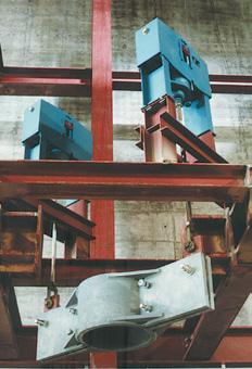
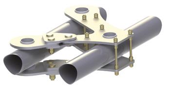
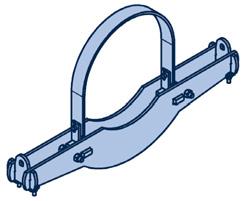
The following points are important for application:
1 All data needed for determination of the correct component and a clearly defined order are outlined in the selection tables.
2 The connection geometries are compatible with those of the LISEGA connection components. Due to the wide load application range, connection components from several LISEGA load groups can be attached.
The dimensions and geometries listed in the selection tables can vary slightly as regards design: The permissible loads apply as shown.
3 The lengths of the connecting lugs are so designed that the connection points always lie outside the economical insulation thicknesses.
4 All pipe clamps and clamp bases can be fitted with corresponding stainless steel inlay plates for use with pipe systems made of austenitic materials. These components can be found on page 4.7.
5 When selecting a suitable pipe clamp the following sequence is to be followed:
5.1 Determination of the relevant page for the outer diameter (OD) of the pipe system to be supported. The normal pipe tolerances are covered.
5.2 Determination of the relevant temperature range in the column for the desired support type, horizontal or vertical.
5.3 Determination of the permissible load to be covered. The permissible operational load taken from the selection table must not be exceeded at any time. The linear interpolation of the permissible load for intermediate temperatures is allowed.
5.4 Checking of installation dimension E and width B for agreement with the installation conditions on site. The dimensions can be taken from the selection tables.
5.5 Checking of the span width in riser clamps (L DIM.).
5.6 Decision as to whether trunnions or shear lugs are to be used for riser clamps type 46/48.
5.7 Agreement of the connection with the load chain required can be checked via the LISEGA load group ranges.
5.8 Specify the component selected by entering the relevant LISEGA type number.
6 When selecting a suitable clamp base the points 5.1 – 5.4 should be followed.
Attention must also be paid to selection of the correct height (dimension H) which depends on the thickness of the insulation.
6.1 The heights specified (dimension H) and the lengths (dimension A) are standard dimensions (see selection tables) and cover the most common cases of application. If required, the components can be supplied with different dimensions.
7 Pipe clamps and clamp bases can be supplied as special designs for unusual applications and conditions (see pages 4.6 to 4.9 for this).
8 In the design and construction of LISEGA pipe clamps and clamp bases, their application in cases of increased requirements was also taken into account. In accordance with the LISEGA quality management system, separate manufacturing is required for this. The type designation thereby changes in the 5th digit by addition of a 5 (see also pages 0.7 and 0.8 on this).
The selection tables on the following pages offer an overview of the fields of application. They are classified in rising stages according to pipe diameters. All pipe clamps and clamp bases coming into consideration for a planned pipe system can therefore be found on one page. The high-temperature range (600°C – 650°C) is included as a supplementary section. The shown loads of the LISEGA pipe clamps consider a force applied conically below 4°.
By coupling two pipe clamps with connection plates type 77 the loads can be doubled. A selection can be found on page 4.67.

45
45 01 41 4.23.73.53.02.32.01.51.00.70.51225706007.5C-4 Temp. of medium 600°C from page 4.52
Load doubling via type 77, see page 4.67
Pipe clamps, clamp bases, OD 26.9 (ND 20), type 42, 43, 45, 49
Temp. of medium 600°C from page 4.52
Load doubling via type 77, see page 4.67
43 02 39 5.85.24.33.62.31.2
45 02 11 4.63.72.6
45 02 11 1.81.41.0 1225506004.4C-4
45 02 31 9.37.86.75.85.04.12.71.4 1225703004.2C-4
45 02 31 6.85.74.94.23.73.02.01.0 1225704005.3C-4
45 02 31 5.34.53.83.32.92.41.50.8 1225705006.4C-4
45 02 31 4.43.73.22.72.42.01.20.6 1225706007.5C-4
45 02 41 8.98.17.56.55.04.43.32.11.51.11225703004.2C-4
45 02 41 6.55.95.54.83.73.22.41.51.10.81225704005.3C-4
45 02 41 5.14.64.33.72.92.51.91.20.90.61225705006.4C-4
45 02 41 4.23.83.53.12.42.11.61.00.70.51225706007.5C-4

Temp. of medium 600°C from page 4.52
Load doubling via type 77, see page 4.67

1225604003.8C-4
1225606005.3C-4
45 03 31 9.68.16.96.05.24.32.81.4 1225703004.2C-4
45 03 32 10109.89.39.09.08.97.3 12259030010.2C-4
45 03 31 6.95.95.04.33.73.12.01.0 1225704005.3C-4
45 03 32 10109.89.39.09.08.95.3 12259040013.0C-4
45 03 31 5.44.63.93.42.92.41.60.8 1225705006.4C-4
45 03 32 10109.89.39.09.08.24.2 12259050015.8C-4
45 03 31 4.53.83.22.82.42.01.30.6 1225706007.5C-4
45 03 32 10109.89.39.09.06.83.5 12259060018.7C-4
45 03 41 9.38.37.86.85.24.63.52.21.61.21225703004.2C-4
45 03 42 8.98.78.26.112259030010.2C-4
45 03 41 6.76.05.64.93.83.32.51.61.10.81225704005.3C-4
45 03 42 8.98.16.04.512259040013.0C-4
45 03 41 5.24.74.43.83.02.61.91.20.90.61225705006.4C-4
45 03 42 9.08.96.44.73.512259050015.8C-4
45 03 41 4.33.93.63.12.42.11.61.00.70.51225706007.5C-4
45 03 42 9.08.45.33.92.912259060018.7C-4
Temp. of medium 600°C from page 4.52
Load doubling via type 77, see page 4.67
Pipe clamps, clamp bases, OD 42.4 (ND 32), type 42, 43, 45, 49
04 17 2.5 10.54566260.19C-D
45 04 11 9.07.25.1 1225703004.3C-4
45 04 11 6.55.23.7 1225704005.4C-4
45 04 11 5.14.02.9 1225705006.5C-4
45 04 11 4.13.32.4 1225706007.6C-4
45 04 39 5.02.8 1225703507.2C-D
45 04 31 18151311108.45.52.8 1630703507.21-4
45 04 32 242423222221137.1 163010035013.41-4
45 04 39 5.04.12.1 1225704508.9C-D
45 04 31 1412108.87.66.34.12.1 1630704508.91-4
45 04 32 242423211916105.4 163010045016.51-4
45 04 39 5.03.31.7 12257055010.5C-D
45 04 31 119.68.27.16.15.13.31.7 16307055010.51-4
45 04 32 2423201715138.54.3 163010055019.71-4
45 04 39 5.04.32.81.4 12257065012.2C-D
45 04 31 9.58.06.95.95.14.32.81.4 16307065012.21-4
45 04 32 2319171413107.13.6 163010065022.81-4
45 04 41 9.99.06.84.33.22.41225703507.0C-4
45 04 42 222217108.16.0163010035013.41-4
45 04 41 10107.76.85.13.22.41.81225704508.6C-4
45 04 42 23221917138.36.14.6163010045016.51-4
45 04 41 109.99.28.06.25.44.12.61.91.412257055010.3C-4
45 04 42 242422191513106.64.93.7163010055019.71-4
45 04 41 9.18.37.76.75.24.53.42.21.61.212257065011.9C-4
45 04 42 2220191613118.85.54.13.1163010065022.81-4

Temp. of medium 600°C from page 4.52
Load doubling via type 77, see page 4.67
45
12258045010.1C-D
45 05 31 161412109.07.54.92.5 16308045010.11-4
45 05 32 242423222219136.7 163012045019.91-4
45 05 39 5.03.92.0 12258055012.0C-D
45 05 31 13119.68.37.26.03.92.0 16308055012.01-4
45 05 32 242423211916105.3 163012055023.61-4
45 05 39 5.04.93.21.6 12258065013.9C-D
45 05 31 119.38.06.96.04.93.21.6 16308065013.91-4
45 05 32 2424201716138.74.4 163012065027.41-4
45 05 41 9.88.05.03.72.81225803508.0C-4
45 05 42 222113107.5163012035016.11-4
45 05 41 109.18.06.03.82.82.11225804509.9C-4
45 05 42 222116107.55.6163012045019.91-4
45 05 41 11109.47.26.44.83.02.21.712258055011.7C-4
45 05 42 23221917128.26.04.5163012055023.61-4
45 05 41 109.68.97.86.05.34.02.51.81.412258065013.6C-4
45 05 42 2423201614106.85.03.7163012065027.41-4
Temp. of medium 600°C from page 4.52
Load doubling via type 77, see page 4.67
Pipe clamps, clamp bases, OD 60.3 (ND 50), type 42, 43, 45, 49
06 17 2.5 10.57594260.27C-D
45 06 11 9.06.74.8 1225703004.4C-4
45 06 12 241813 1630803007.41-4
45 06 11 6.54.83.4 1225704005.5C-4
45 06 12 17139.4 1630804009.31-4
45 06 11 5.13.82.7 1225705006.6C-4
45 06 12 13107.4 16308050011.21-4
45 06 11 4.13.12.2 1225706007.7C-4
45 06 12 118.56.1 16308060013.11-4
45 06 39 5.03.7 122510040011.6C-D
45 06 31 2420171513117.43.7 163010040011.61-4
45 06 32 242423222222158.0 163012040018.11-4
45 06 39 5.02.9 122510050013.9C-D
45 06 31 18161311108.65.62.9 163010050013.91-4
45 06 32 242423222218126.2 163012050021.91-4
45 06 39 5.04.52.3 122510060016.3C-D
45 06 31 1513119.68.47.04.52.3 163010060016.31-4
45 06 32 2424232018159.85.0 163012060025.71-4
45 06 39 5.03.81.9 122510070018.6C-D
45 06 31 12119.48.17.15.93.81.9 163010070018.61-4
45 06 32 2422191715128.24.2 163012070029.41-4
45 06 41 9.89.15.74.23.2122510040011.2C-4
45 06 42 2219129.06.7163012040018.11-4
45 06 41 9.99.27.04.43.22.4122510050013.6C-4
45 06 42 2219149.47.05.2163012050021.91-4
45 06 41 10108.57.55.63.52.62.0122510060015.9C-4
45 06 42 23221816127.65.64.2163012060025.71-4
45 06 41 11109.27.16.34.73.02.21.6122510070018.3C-4
45 06 42 242321191513106.44.73.5163012070029.41-4

08 17 5.0 1395120320.54C-2
45 08 19 5.0 1225703006.6C-D
45 08 11 17139.2 1630703006.61-4
45 08 12 272316 16301003009.41-4
45 08 19 5.0 1225704008.3C-D
45 08 11 14107.5 1630704008.31-4
45 08 12 221611 163010040011.71-4
45 08 19 5.0 1225705009.9C-D
45 08 11 118.36.0 1630705009.91-4
45 08 12 17129.1 163010050014.11-4
45 08 19 5.04.7 12257060011.6C-D
45 08 11 9.06.64.7 16307060011.61-4
45 08 12 13107.3 163010060016.41-4

12257060011.6C-D
16307060011.61-4 45
45
163010060016.51-4
12257075014.1C-D
16307075014.11-4
163010075020.11-4
Temp.
Load
43 10 18 2.52.52.5 12200502.5C-D
43
16200502.51-4
45
45 10 11 17139.7 1630803508.71-4
45 10 19 5.0 12258050011.6C-D
45 10 11 129.36.7 16308050011.61-4
45 10 19 5.0 12258065014.4C-D
45 10 11 9.47.05.0 16308065014.41-4
45 10 19 5.04.0 12258080017.2C-D
45 10 11 7.55.64.0 16308080017.21-4


Heat-resistant materials, see pages 0.9 and 4.4
45
45
45 13 19 5.0 12259055014.3C-D
45 13 11 139.76.9 16309055014.31-4
45 13 19 5.0 12259070017.5C-D
45 13 11 9.97.45.3 16309070017.51-4
45 13 19 5.04.2 12259085020.6C-D
45 13 11 8.05.94.2 16309085020.61-4


Load


43
43
49
Temp. of medium 600°C from page 4.52
Load doubling via type 77, see page 4.67


Pipe
49
Temp. of medium 600°C from page 4.52
Load doubling via type 77, see page 4.67



Load


Load



4.
4. 66 33
Load


Pipe clamps, clamp bases, OD 762 (ND 750), type 42, 44, 46, 48, 49
Load






4. T1 25 435422364286
4.

4.
Temp. of medium 600°C from page 4.52
Load doubling via type 77, see page 4.67
4. T3 35 665617602589576522402213 71205028501302119249746511671688 8 - 30
4. T3 36 680680680680673608468250 71210028501602264279848513391885
4. T3 37 760760760760759742580310 8121002850160252432095201548218010 - 40
4. T3 42 106806046205028501109951257345621916 5 - 8
4. T3 43 147108805120502850110118815083707161054 6 - 9
4. T3 44 25818914061205028501301662213144510051476
4. T3 45 41036727120071205028501302104270044512491838 8 -
4. T3 46 48042431924071212028501602471315849014172044 9 - 30
4. T3 47 5885835714203098121202850160294136844901672239910 - 40






Pipe clamps, OD 244.5 (ND 225), type 44, 48
Pipe clamps, OD 267 (ND 250), type 44, 48
Pipe clamps, OD 273 (ND 250), type 44, 48


clamps, OD 508 (ND 500), type 44, 48


15414112510995835122431014002100292471


Pipe clamps, OD 1016 (ND 1000), type 44, 48
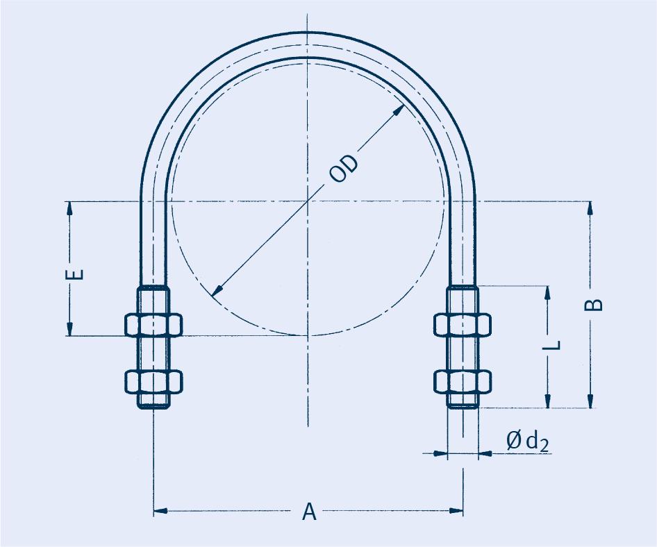
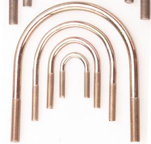
40 01 .821.3 30 70M6 x 6511 0.05
40 02 .826.9 35 70M6 x 6513 0.05
40 03 .833.7 40 70M6 x 6517 0.05
40 04 .842.4 53 75M10 x 6521 0.15
40 05 .848.3 60 75M10 x 6524 0.16
40 06 .860.3 72 85M10 x 7030 0.18
40 07 .873.0 87 95M12 x 7537 0.30
40 08 .876.1 91 95M12 x 7538 0.31
40 09 .888.9 103 100M12 x 7544 0.32
40 10 .8108.0 123 115M12 x 7554 0.36
40 11 .8114.3 130 115M12 x 7557 0.37
40 14 .8139.7 155 130M12 x 7570 0.42
40 17 .8168.3 188 155M16 x 9584 0.91
40 22 .8219.1 238 180M16 x 95110 1.08
40 27 .8273.0 295 215M20 x 110137 2.07
40 32 .8323.9 350 245M20 x 110162 2.35
40 36 .8355.6 381 260M20 x 110178
40 41 .8406.4 432 285M20 x 110203 2.80
40 46 .8457.2 485 320M24 x 125229 4.55
40 51 .8508.0 537 345M24 x 125254 4.90
40 56 .8558.8 587 370M24 x 125279 5.35
40 61 .8609.6 638 395M24 x 125305 5.70
40 66 .8660.4 689 425M24 x 125330 6.15
40 71 .8711.2 740 450M24 x 125356 6.50
40 76 .8762.0 790 475M24 x 125381 6.90
40 81 .8812.8 843 501M24 x 125406 7.30
40 86 .8864.0 895 526M24 x 125432 7.70
40 91 .8914.4 943 550M24 x 125457 8.00 5th digit: 1 = carbon steel 3 = stainless steel
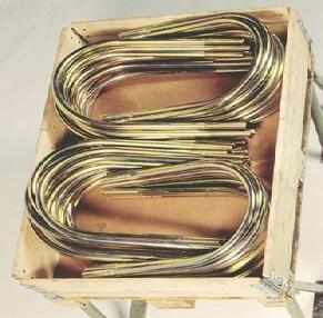
U-bolts
type 40 01 .8 to 40 91 .8
Type 40 mainly serves to fasten pipe systems to existing steel structures.
Order details: U-bolt type 40 .. .8
Scope of delivery: incl. 4 nuts
Weld-on lugs for pipes type 41 D9 11 to 41 79 12
Permissible load at 80°C = normal operating conditions (load case H / level A/B) of the corresponding load group (3rd digit in the type designation, see “Max. permissible load for static components”, page 0.6).
Existing stress in the specified weld seam 50 N/mm2 at 4° load angle.
Material: carbon steel
type 41 .. 11 smax = 10mm type 41 .. 12 smax = 100mm
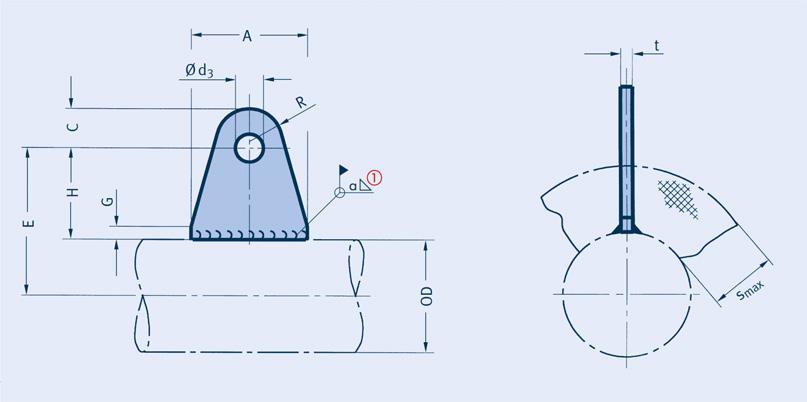
Order details:
lug for pipes type 41 .9 1.
Reduction factors of permissible load at increased temperatures:
Smax = 10mm weight type E a [kg]
41 06 13353.00.13
41 07 13303.00.13
41 08 13353.00.13
41 09 13303.00.13
41 09 14353.00.24
41 10 13303.00.13
41 10 14353.00.25
41 11 13303.00.14
41 11 14353.00.25
41 13 13253.00.14
41 13 14303.00.25
41 14 13253.00.14
41 14 14404.50.62
41 16 13253.00.14
41 16 14404.50.62
41 17 13253.00.25
41 17 14405.50.87
41 19 13203.00.25
41 19 14355.50.88
41 22 13203.00.25
41 22 14355.50.90
41 24 13153.00.25
41 24 14305.50.90
41 26 13103.00.25
41 26 14255.50.90
41 27 13153.00.26
41 27 14255.50.90
41 32 13154.50.62
41 32 14256.51.40
41 36 13-104.50.62
41 36 1456.51.50
41 37 1304.50.62
41 37 14156.51.50
41 41 13-154.50.65
41 41 14-56.51.50
41 42 13-104.50.65
41 42 1456.51.50
41 46 13-205.50.90
41 46 1406.53.40
41 51 13-305.50.90
41 51 14-106.53.40
41 56 13-405.50.90
41 56 14-206.53.40
41 61 13-455.50.90
41 61 14-306.53.40
41 66 13-555.50.90
41 66 14-356.53.40
41 71 13-655.50.90
41 71 14-456.53.40
41 76 13-755.50.90
41 76 14-556.53.40
Smax = 100mm weight type E a [kg]
41 06 151353.00.44
41 07 151353.00.44
41 08 151353.00.44
41 09 151353.00.44
41 09 161404.50.75
41 10 151353.00.44
41 10 161404.50.75
41 11 151353.00.45
41 11 161404.50.75
41 13 151353.00.46
41 13 161404.50.77
41 14 151353.00.47
41 14 161454.51.60
41 16 151353.00.47
41 16 161454.51.70
41 17 151404.50.78
41 17 161505.52.30
41 19 151354.50.78
41 19 161455.52.30
41 22 151354.50.80
41 22 161455.52.30
41 24 151304.50.80
41 24 161455.52.40
41 26 151254.50.80
41 26 161405.52.40
41 27 151304.50.80
41 27 161455.52.40
41 32 151304.51.70
41 32 161456.53.70
41 36 151154.51.70
41 36 161256.53.70
41 37 151204.51.80
41 37 161306.53.70
41 41 151054.51.80
41 41 161156.53.70
41 42 151154.51.80
41 42 161256.53.80
41 46 151005.52.40
41 46 161206.57.10
41 51 15955.52.50
41 51 161106.57.10
41 56 15855.52.50
41 56 161056.57.10
41 61 15805.52.50
41 61 16956.57.10
41 66 15705.52.50
41 66 16856.57.10
41 71 15605.52.50
41 71 16806.57.20
41 76 15505.52.50
41 76 16706.57.20
Permissible loads at 80°C = normal operating conditions (load case H / level A/B) of the specified load group in each case (see “Max. permissible load for static components”, page 0.6).
60.3C-22217.5812.5
73.0C-22217.58 12.5
76.1C-22217.58 12.5
88.9C-22217.58 12.5 88.92-32822.510 16.5
108.0C-22217.58 12.5 108.02-32822.510 16.5
114.3C-22217.58 12.5 114.32-32822.510 16.5 133.0C-22217.58 12.5
133.02-32822.51016.5 139.7C-22217.58 12.5
139.73-43730.015 20.5
159.0C-22217.58 12.5 159.03-43730.015 20.5 168.32-32822.510 16.5 168.34-54032.518 24.5 193.72-32822.510 16.5 193.74-54032.51824.5 219.12-32822.51016.5 219.14-54032.51824.5 244.52-32822.51016.5 244.54-54032.51824.5 267.02-32822.51016.5 267.04-54032.51824.5 273.02-32822.51016.5 273.04-54032.51824.5 323.93-43730.01520.5 323.95-65040.020 34.0 355.63-43730.01520.5 355.65-65040.02034.0 368.03-43730.01520.5 368.05-65040.02034.0 406.43-43730.01520.5 406.45-65040.02034.0 419.03-43730.01520.5 419.05-65040.02034.0 457.24-54032.51824.5 457.26-76550.02541.0 508.04-54032.51824.5 508.06-76550.02541.0 558.84-54032.51824.5 558.86-76550.02541.0 609.64-54032.51824.5 609.66-76550.02541.0 660.44-54032.51824.5 660.46-76550.02541.0 711.24-54032.51824.5 711.26-76550.02541.0 762.04-54032.51824.5 762.06-76550.02541.0
Stress existing in the specified weld seam 50 N/mm2 at 4° load angle.
Weld-on lugs for pipe elbows (R 1.5 OD) type 41 06 13 to 41 76 16
Material: carbon steel
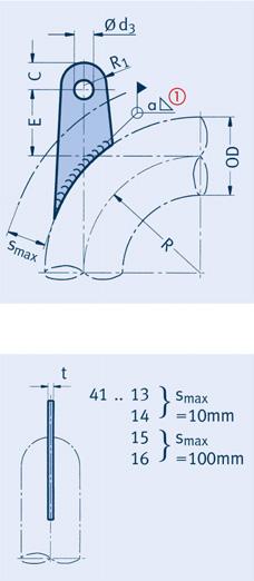
Reduction factors of permissible load at increased temperatures:
Order details: weld-on lug for pipe elbows R 1.5 OD type 41 .. 1.
Connection plates for coupling pipe clamps type 43
type 77 09 39 to 77 19 39
By coupling 2 pipe clamps with type 77 the loads can be doubled.
Order details: connection plate type 77.. 39
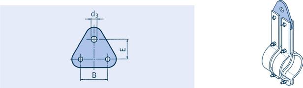
Connection plates for coupling pipe clamp type 44 up to 600°C
type 77 22 .. to 77 T4 ..
Type designation of the connection plates: the figures 44 of the clamps to be coupled must be replaced by the figures 77.
Example: connection plate for type 44 66 38 77 66 38.
The load group for the upper connection (type 60) must be stated when ordering.
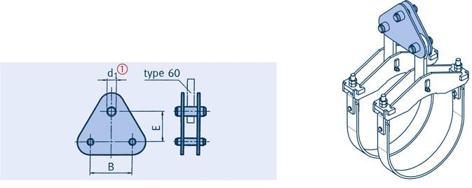
Order details: connection plate type 77.. .. load group ...
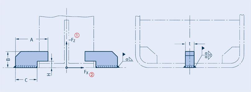
49
49
49
49
49
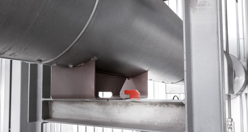
Lift-off restraints for clamp base type 49 type 49 00 01 to 49 00 05
Material: plate t 15mm : S235JR plate t 20mm : S355J2
The following short duration lift-off loads are permissible for the clamp bases: type 49 01 .. to 49 76 .. 10% type 49 81 .. to 49 T4 .. 7% of the catalog load.
When used as a guide it must be ensured that the pipe supports are secured against rotation about the pipe axis. FX is the max. lateral load at a weld seam stress of 50 N/mm2 in the load case H (level A/B). Simultaneous lift-off loads are taken into consideration.
Order details: lift-off restraint type 49 00 ..
Care must be taken during transport that none of the clamp components are damaged. When stored in the open the clamps must be protected from dirt and water.
LISEGA pipe clamps are delivered ready for installation, with all the necessary bolts. For reason of more optimize dispatch clamps can be supplied partially assembled.
Type 42
This clamp is used as a horizontal clamp in connection with threaded eye nut type 60. When tightening the bolts, care must be taken that the clamp halves are parallel to each other. The bolts are to be secured with lock nuts.
Type 43
Connection is made with this horizontal clamp via a separate connection pin with a threaded eye nut type 60. The pins must be secured with the cotter pins provided; otherwise proceed as with type 42.
Type 44 U-bolt/ strap for temperatures up to 600°C
These clamps consist of an upper section with a connecting lug and, depending on load and temperature range, a U-bolt with an inlay plate or a flat steel strap as lower section. For installation, remove the pre-assembled lower part by loosening the locking nuts or removing the connection pins. The upper section is seated on the piping and the lower one inserted and held by bolting the U-bolt or gib the flat steel strap. After alignment of the clamp the bolts are to be firmly tightened. The U-bolts are secured with lock nuts and the flat steel straps with tab washers under the hexagon nuts.
Type 44 for temperatures over 600°C
These clamps consist of an upper section with a connection lug and restrainer and a flat steel strap as lower part.
For installation the restraint and strap must be taken off by removing the outer threaded rods and the connection pins. After attaching the upper section to the hanging part the restraint and strap can be reconnected.
Afterwards they are pinned and the threaded rods are fitted. All parts must then be firmly secured.
Installation of type 44 for temperatures over 600°C
Type 45
When installing these clamps care must be taken to place the spacers supplied onto the bolts between the clamp halves. The bolts are then tightened and locked. The clamp is hung up via the outer support pins, which are secured with washers and cotter pins. The specified height of the clamp is set by tightening the suspended parts and creating a force-and form-fitting connection with the shear lugs.
This riser clamp is supplied in single parts sealed in plastic shrink wrap.
For installation it is best to first fit the front plates into the suspended parts. These parts should be tightened at the lowest level, then both side plates can be attached one after another. In the case of large clamps, the opposite side must hereby be temporarily propped up.
For installation, both side plates are seated on the trunnions and connected with the threaded rods. The nuts should be only loosely tightened here. For large clamps the components should be temporarily propped up.
The front plates can now be pushed from below into the intake slots and connected to the suspended parts. The connection points between front and side plates are made by aligning and firmly tightening the pre-assembled locking plates . The specified height of the clamp is set by tightening the suspended parts, creating a force- and form-fitting connection with the trunnions.
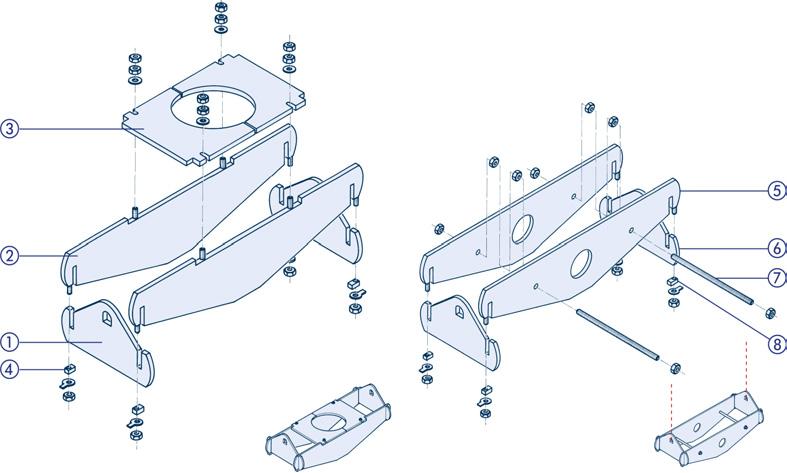
After that, the top plates for the shear lugs are inserted and bolted on. The connection points between front and side plates are secured by aligning and firmly tightening the pre-assembled locking plates .
The specified height is set by tightening the suspended parts, creating a force- and formfitting connection with the shear lugs.
This riser clamp is supplied in single parts sealed in shrink wrap. First of all, a side plate should be prepared by attaching the threaded rods
The horizontal clamp functions flawlessly in any operating condition if the secured boltings are free of any play. Under normal operating conditions maintenance is not required.
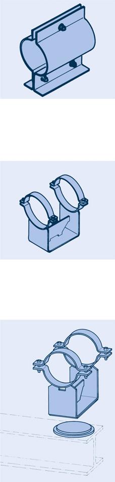
Care must be taken during transport that no clamp base components are damaged. When stored in the open, the clamp bases must be protected from dirt and water.
If not agreed otherwise, LISEGA clamp bases are delivered pre-assembled and ready for installation. For reasons of efficient dispatch clamp bases can be delivered partially assembled. In any event the clamp base is supplied with all the necessary bolts.
LISEGA clamp bases are slidable supports that are fastened to pipe systems by clamping tension. On installation it is essential that the whole clamp base bottom lies flush and can slide unobstructed over the given stretches.
If required, the lower parts can be welded to the supporting surface.
Different designs are used depending on the height of the support, the pipe diameter, the support load and the operating temperature. The following points are hereby to be observed:
Type 49 .. .1 and 49 .. .2
This clamp base design is made up of two halves to be fitted to each side of the pipe. The cornered surfaces form the base. In this lower part the clamp base halves are firmly bolted to each other. The upper bolting serves for clamping tension in the piping against slipping.
Type 49 .. .3, 49 .. .4 and 49 .. .5
The base part of the clamp base forms a firm support for the pipe to be laid in. The upper half provides clamping tension and is to be firmly bolted.
Under normal circumstances no maintenance is required.
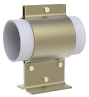
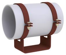
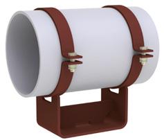
ProducT 5 grouP
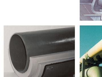
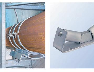
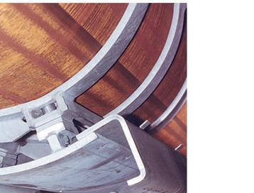
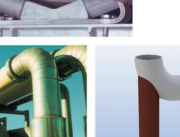

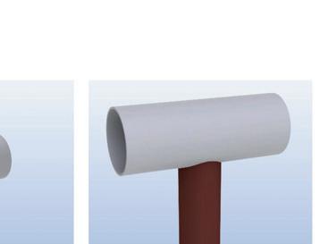
Pipe systems arranged horizontally over longer stretches are supported by movable support bearings and fixed points. To ensure thermal expansion displacement with little friction, the bearing points are designed to be rolling or sliding.
For pipe systems of larger diameters and especially where high loads are caused by fluids and insulation weights, the optimum solution is provided by roller bearings of high load-bearing capacity, great reliability and extremely low friction resistance.
These components offer a suitable standard solution for a wide range of applications within product group 5.
For use outside the standard range specially modified designs can be supplied.
In the development of standard roller bearings, the particular practical requirements that had to be met, were taken into account
The design of the roller bearing enables optimum corrosion protection through hot dip galvanization.
The bearing axles are made of austenitic material with polished surfaces. As bearings for the rollers, bushings made of a sintered teflon / bronze composite material are fitted. They are maintenance-free and guarantee smooth dry run characteristics A formed collar on the bushings minimizes starting friction on lateral loading.
The bearing axles are permanently fixed in the middle section of the base body of the double cylinder roller bearings Special securing devices on the side bracket are not required.
The rollers are of high-tensile carbon steel. The running surfaces are machined.
To balance lateral offset in anchor bolts on site, the intake holes of the base body are slotted. The installation height (E dimensions) within a load group range are the same for rigid and laterally movable roller bearings.
Data on material quality, norms, calculations and welding can be found in the technical specifications, pages 0.9 and 0.10.
Standardization of the products permits efficient series production and storage for most components. For individual manufacture or fabrication in small batches, modern order logistics ensures rapid production and delivery.
Technical data for roller bearings:
rolling resistance of the rollers max. 4%
rolling resistance on lateral displacement max. 4%
temperature range for nominal load – 30°C to + 80°C
permissible lateral loading 35% of nominal load
permissible lift-off load 10% of nominal load
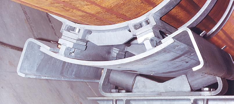
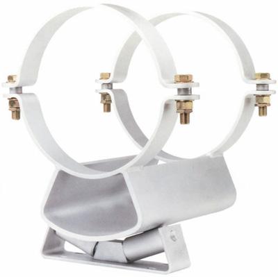

The roller bearings can be fastened with simple bolted connections or welded to the supporting surface. In all cases the whole base plate must lie flush on the surface.
On slight lateral offset of existing anchor bolts the roller bearings can be easily aligned using the existing slot holes.
Pipe saddles for welding are supplied with a weldable primer as corrosion protection (see technical specifications, pages 0.10 and 0.11).
Clamp-fastened pipe saddles are supplied ready-to-install. Close attention must be paid to true-to-size seating and sufficient prestressing.
When installing lift-off restraints, normal displacement over the whole range must be ensured to allow sufficient play between rollers and lift-off restraints.
Their special design and their manufacturing quality offer the following benefits in application:
maintenance of minimum rolling resistance (max. 4%)
absorption of realistic lateral loading for double taper and double cylinder roller bearings (35% of the support load)
for double cylinder roller bearings the whole support load can be carried by a single roller
absorption of lateral displacement possible by laterally movable designs
safe and simple design of lift-off restraints
pipe saddles facilitate load transmission into the pipe walls
pipe saddle design minimizes heat transmission
hot dip galvanized corrosion protection for all roller bearings
maintenance-free operation
roller axle made of non-rusting steel
teflon-bronze composite bushings
wide range of support diameters (OD 60mm – OD 1350mm)
high load capacity (max. support load 120kN)
low installation heights (see selection table for ‘E’ dimensions)
Cylinder roller bearings type 51 08 19 to 51 35
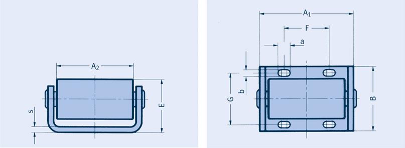
type 51 19
Double taper roller bearings type 52 04 19 to 52 35 19
Surface: hot dip galvanized
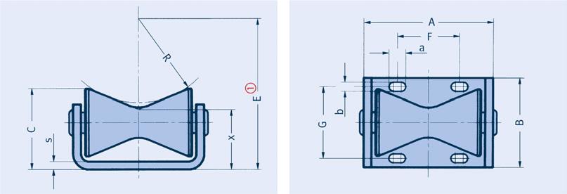
Double taper roller bearings (laterally movable) type 52 04 29 to 52 35 29
Surface: hot dip galvanized Order
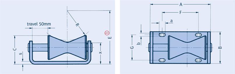
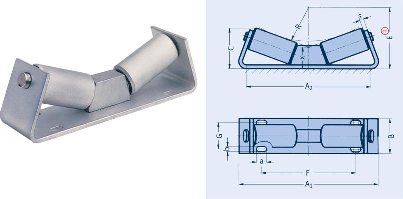
53
53
53
53
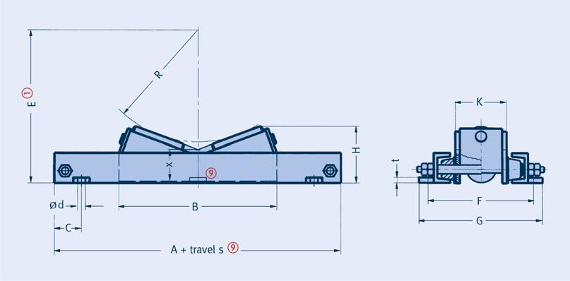
Double cylinder rollers bearing type 53 08 19 to 53 12 19
Order details: double cylinder roller bearing type 53 .. 19
Double cylinder roller bearings (laterally movable) type 53 08 29 to 53 12 29 travel s = lateral pipe movement
Surface: hot dip galvanized
Order details: double cylinder roller bearing (laterally movable) type 53 29 with s = …mm
Weld-on pipe saddles type 54 06 19 to 54 81 19
Material: plate s ≤ 15mm: S235JR plate s ≥ 20mm: S355J2
Surface: weldable primer
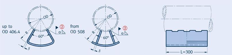
Order details:
weld-on pipe saddle type 54 19 R = …mm
Pipe saddles with clamps type 54 06 29 to 54 81 29
Surface: hot dip galvanized
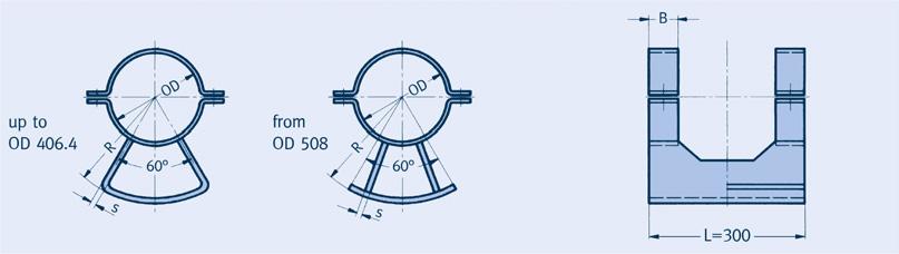
Order
54 .. 29 R = …mm
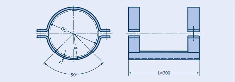
Pipe trays with clamps type 54 06 39 to 54 81 39
Surface: hot dip galvanized
Order details: pipe tray with clamps type 54 .. 39
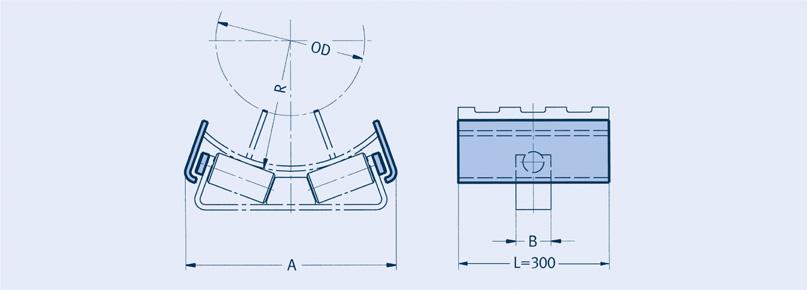
Lift-off restraints type 55 08 19 to 55 12 19
Surface: hot dip galvanized
Order details: lift-off restraint type 55 .. 19 for special pipe saddles type 54 .9 R = …mm
LISEGA offers a complete product program of insulated pipe supports for all kinds of low temperature pipe systems. These products are normally used in industrial processes for the production, transport and distribution of liquefied gases These can be propane and butane (LPG), methane (LNG), ethylene, nitrogen, ammonia etc..
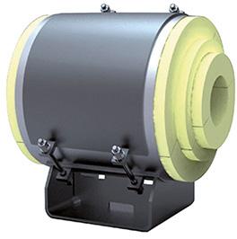
Insulation foam with thicknesses of 80mm to 100mm are single layer with an extended step at either side. For type 56, insulation foam thicknesses of 130mm and higher are supplied as double-layer with two steps To achieve load transmission for axial stop type 57, the HD-PUF insulation is designed as single-layers.
10050 / 50
13050 / 40 / 40
15050 / 50 / 50
18050 / 80 / 50
20050 / 100 / 50
25075 / 100 / 75
LISEGA insulated pipe supports are standardized and designed according to recognized international technical codes and standards. They cover pipe sizes ranging from OD 21.3mm to OD 965.2mm, with insulation thicknesses from 25mm to 250mm. The supports are made from materials suitable for the specified loads and temperatures (temperature of medium as low as -196°C).
The material of the insulated standard pipe supports is made from fire-retarding polyurethane foam of high density (HD-PUF) and forms an integral part of the piping insulation.
The HD-PUF insulation is molded in heavy duty molds under carefully controlled conditions in respect of temperature and air humidity. This process ensures dimensional stability as well as clean sharp edges that fit neatly with the adjacent line insulation material on site.
To guarantee form stability, the molds are stored for a fixed period of time in order to cure. For insulations of higher thicknesses stepped joints are provided to match the layering of the adjoining line insulation. This method, also known as “shiplapping“, provides a reliable interlocking connection to each layer and prevents a direct heat path from the surface of the insulation through to the surface of the piping.
The stepped joints are 25mm long but can be supplied in 50mm steps on request. Insulation foam with thicknesses up to 50mm are single-layer designs without stepping.
Both single-layer and double-layer HD-PUF insulation have stepped longitudinal joints. The size of these joints must be adjusted during installation to a specified gap dimension to ensure a clamping force from the insulated, pipe support on the piping. Once installed the longitudinal gaps are then filled with a flexible insulating foam. The clamping force, which is applied by means of disc spring bolting, prevents relative movement between pipe support and piping.
A laminated aluminum/polyester vapor barrier is factory-bonded to the outer surface of the HD-PUF insulation. The vapor barrier overlaps the longitudinal joints and is sealed at site with a special vapor barrier adhesive tape. Directly after installation of the insulated pipe support, all exposed HD-PUF surfaces must be protected from moisture. For this purpose a cryogenic, elastomeric coating is applied as vapor barrier.
For the HD-PUF insulation three standard color-coded densities for various load requirements are available.
160kg/m3 – yellow 224kg/m3 – red 320kg/m3 – green
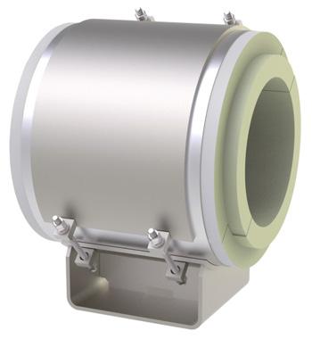
Insulated pipe support base
LISEGA standardized insulated pipe supports are designed to be clamped mechanically to the piping by means of disc spring bolting. The pipe support steel cradle, which houses the HD-PUF insulation, is made of carbon steel and hot-dip galvanized as standard.
Material grades, welding and surface treatment comply with the LISEGA standard specifications. The integrated LISEGA quality assurance system applies to both the manufacture and preassembly of the pipe supports. Inspection and testing procedures guarantee compliance with the required specifications.
HD-PUF insulation with stepped longitudinal joints and stepped front ends
steel cradle
metal protective shield
disc spring bolting
vapor barrier
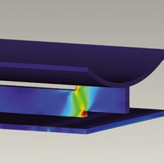

LISEGA insulated standard pipe supports are supplied with detailed installation instructions. Every support is clearly marked according to the LISEGA type designation system. The flexible gap filler insulation foam, as well as the special vapor barrier sealing tape are part of the scope of supply. Additional site installation materials such as cryogenic adhesives and mastics can be supplied on request.
LISEGA insulated pipe supports are completely preassembled and supplied in appropriate packaging to protect them from surface damage and humidity during transport and storage.
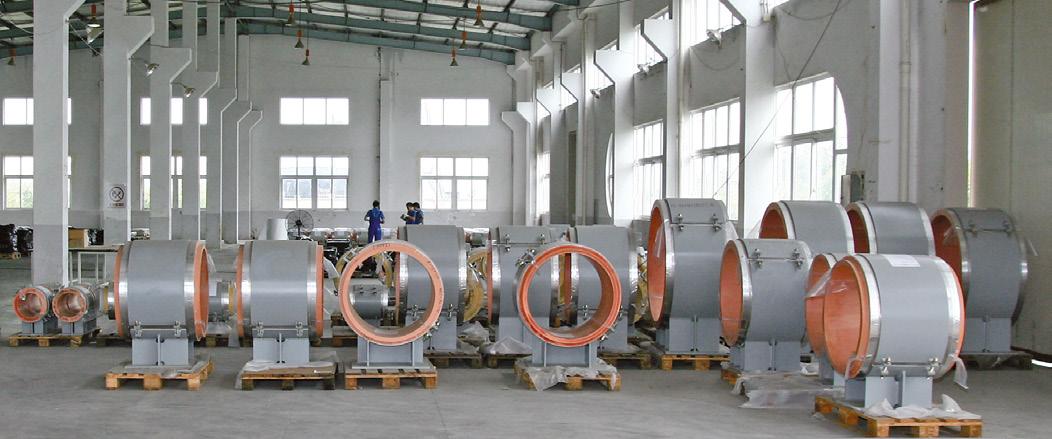
Type 56 is a conventional insulated pipe support and functions as a slide or guide support. Type 57 is similar to type 56 but serves as an axial stop that absorbs increased axial loads by means of thrust rings. The thrust rings on the piping consist of two half-rings which are welded together at site to form a single ring. The rings, which are movable on the piping, are fixed by means of shear lugs welded onto the pipe.
This patented design offers the advantage of fixing the insulated pipe support to the piping after final positioning. There is no need to disassemble any existing or already installed steelwork. The thrust rings and shear lugs are made of stainless steel and form part of the scope of supply.
For high vertical loads or high lateral loads, double clamp bases or guided supports are required. For this purpose, LISEGA’s insulated pipe supports can be extended as required. Each variant is given a suffix after the 6th digit which describes the type of guide used. The pipe support can be ordered in the following designs:
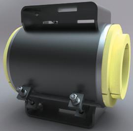
G2A: Angulated clamp base pipe support (laterally guided)
G2P: Double clamp base pipe support (parallely guided)
G3: Triple clamp base pipe support
G4: Quadruple clamp base pipe support
Type 56 as well as type 57 can be ordered with these guide options. A type 57 can be used e.g. as a quadruple pipe support in a vertical pipe.
LISEGA takes pride in offering solutions to their clients and will gladly assist in any special inquiry.
Special pipe sizes can be accommodated.
For large axial movements, special lengths can be supplied.
The use of an insulated pipe support as a hanger (e.g. in combination with spring or constant hangers) is possible. In this case the shoe of the clamp base is replaced by a special pipe clamp type 43. The clamp is then designed for the particular conditions existing in each case.
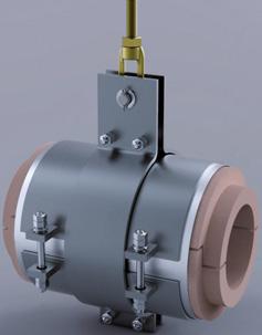
Deviations from the standard HD-PUF densities can be supplied, e.g. a density of 500kg/m3 for high loads.
The use of the pipe support on sliding components is possible. For this purpose a stainless steel plate is fixed to the underside of the shoe.
For special applications when increased loads have to be absorbed, laminated wooden blocks can be utilized.
The installation dimension ‘E’ can be adjusted but it must be considered that changes in the ‘E’ dimension can influence the design and the permissible loads. The actual operating loads must therefore be specified when ordering.
All details required for product selection can be found in the special HIPAC® catalog.
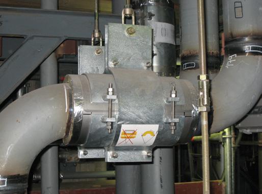
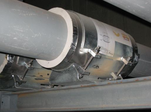
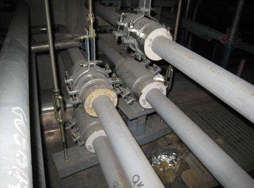
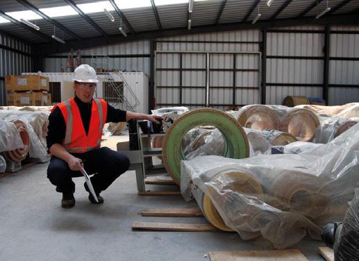
Material: S235JR
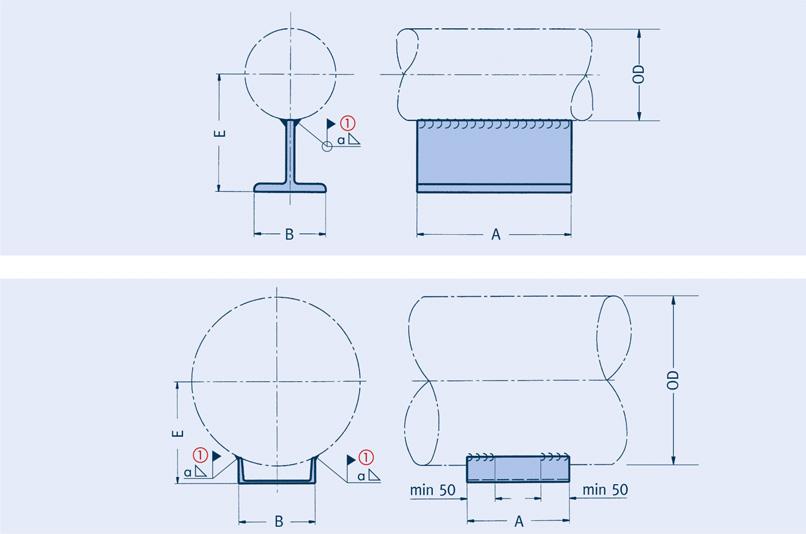
58 05 .148.333.7x4.5a3.0242501000
58 06 .160.333.7x4.5a3.0302501000
58 06 .260.348.3x5.0b3.0302501100
58 07 .173.033.7x4.5a3.0372501000
58 07 .273.048.3x5.0 b3.0372501100
58 08 .176.133.7x4.5a3.0382501000
58 08 .276.148.3x5.0b3.0382501100
58 09 .188.933.7x4.5a3.0442501000
58 09 .288.948.3x5.0b3.0442501100
58 10 .1108.048.3x5.0b3.0543001150
58 10 .2108.073.0x7.0c3.0543001150
58 11 .1114.348.3x5.0b3.0573001150
58 11 .2114.373.0x7.0c3.0573001150
58 13 .1133.048.3x 5.0b3.0673001150
58 13 .2133.073.0x7.0c3.0673001150
58 14 .1139.773.0x 7.0c3.0703001150
58 14 .2139.788.9x5.6d3.0703001150
58 16 .1159.073.0x 7.0c3.0803001150
58 16 .2159.088.9x5.6d3.0803001150
58 17 .1168.373.0x7.0c3.0843001150
58 17 .2168.388.9x 5.6d3.0843001150
58 19 .1193.788.9x5.6d3.0973501150
58 19 .2193.7114.3x8.8e5.0973501150
58 22 .1219.188.9x5.6d3.01103501200
58 22 .2219.1114.3x8.8e5.01103501200
58 24 .1244.588.9x5.6d3.01223501200
58 24 .2244.5114.3x8.8e5.01223501200
58 26 .1267.0114.3x 8.8e5.01343501200
58 26 .2267.0139.7x10f7.01343501200
58 27 .1273.0114.3x8.8e5.01373501200
58 27 .2273.0139.7x10f7.01373501200
58 32 .1323.9139.7x10f7.01624001250
58 32 .2323.9219.1x8.0g5.01624001250
58 36 .1355.6139.7x10f7.01784001250
58 36 .2355.6219.1x8.0g5.01784001250
58 37 .1368.0139.7x 10f7.01844001250
58 37 .2368.0219.1x8.0g5.01844001250
58 41 .1406.4139.7x10f7.02034501300
58 41 .2406.4219.1x8.0g5.02034501300
58 42 .1419.0139.7x10f7.02104501300
58 42 .2419.0219.1 x8.0g5.02104501300
58 46 .1457.2219.1x8.0g5.02295001300
58 46 .2457.2323.9x10h7.02295001300
58 51 .1508.0219.1x8.0g5.02545001350
58 51 .2508.0323.9x10h7.02545001350
58 56 .1558.8219.1x 8.0g5.02795501350
58 56 .2558.8323.9x10h7.02795501350
58 61 .1609.6323.9x10h7.03055501400
58 66 .1660.4323.9x10h7.03306001400
58 71 .1711.2323.9x10h7.03566001450
58 76 .1762.0323.9x10h7.03816501450
58 81 .1812.8323.9x10h7.04066501500
58 91 .1 914.4 323.9x10h7.04577001550
For the selection of stanchions consult the table and diagram on page 5.15.
Type 58 .. 11 Type 58 .. 12
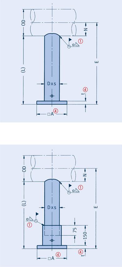
Type 58 .. 21 Type 58 .. 22
For stanchion D = 88.9 mm (designation ‘d’). Permissible load = 0.36 x 11kN (see table and diagram on page 5.15) = 3.96kN. ... See page 5.15.
Example: Telescopic stanchion for pipe OD = 244.5mm, E = 800mm (as sliding shoe). The stanchion length amounts to: L = E-N (see data in selection table) L = 800mm – 122mm = 678mm.
Order details: stanchion for horizontal pipes type 58 , E = ...mm
Type 58 .. 13
Type 58 .. 14
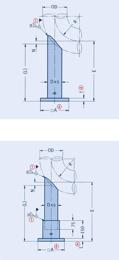
Type 58 .. 23
Type 58 .. 24
... See page. 5.15.
Example: Stanchion for short radius elbow radius R OD, OD = 419mm, E = 750mm (as anchor).
Stanchion length: L = E-N (see data in selection table), L = 750mm – 50mm = 700mm.
For stanchion D = 139.7mm (designation ‘f’).
Permissible load = 0.41 x 22.5kN (see table and diagram on page 5.15) = 9.2kN.
Order details:
stanchion for short radius elbows R OD type 58 .. .., E = ...mm
58 05 .348.333.7x4.5a3.0102501000
58 06 .360.333.7x4.5a3.0102501000
58 06 .460.348.3x5.0b3.0102501100
58 07 .373.033.7x4.5a3.0152501000
58 07 .473.048.3x5.0b3.0152501100
58 08 .376.133.7x4.5a3.0152501000
58 08 .476.148.3x5.0b3.0152501100
58 09 .388.933.7x4.5a3.0152501000
58 09 .488.948.3x5.0b3.0152501100
58 10 .3108.048.3x5.0b3.0152501100
58 10 .4108.073.0x7.0c3.0152501100
58 11 .3114.348.3x5.0b3.0202501100
58 11 .4114.373.0x7.0c3.0202501100
58 13 .3133.048.3x 5.0b3.0202501100
58 13 .4133.073.0x7.0c3.0202501100
58 14 .3139.773.0x 7.0c3.0253001100
58 14 .4139.788.9x5.6d3.0253001100
58 16 .3159.073.0x 7.0c3.0253001100
58 16 .4159.088.9x5.6d3.0253001100
58 17 .3168.373.0x7.0c3.0303001100
58 17 .4168.388.9x 5.6d3.0303001100
58 19 .3193.788.9x5.6d3.0303001100
58 19 .4193.7114.3x8.8e5.0303001100
58 22 .3219.188.9x5.6d3.0353001100
58 22 .4219.1114.3x8.8e5.0353001100
58 24 .3244.588.9x5.6d3.0353001100
58 24 .4244.5114.3x8.8e5.0353001100
58 26 .3267.0114.3x 8.8e5.0403001100
58 26 .4267.0139.7x10f7.0403001100
58 27 .3273.0114.3x8.8e5.0453501100
58 27 .4273.0139.7x10f7.0453501100
58 32 .3323.9139.7x10f7.0503501100
58 32 .4323.9219.1x8.0g5.0503501100
58 36 .3355.6139.7x10f7.0403501100
58 36 .4355.6219.1x8.0g5.0403501100
58 37 .3368.0139.7x 10f7.0453501100
58 37 .4368.0219.1x8.0g5.0453501100
58 41 .3406.4139.7x10f7.0503501100
58 41 .4406.4219.1x8.0g5.0503501100
58 42 .3419.0139.7x10f7.0503501100
58 42 .4419.0219.1 x8.0g5.0503501100
58 46 .3457.2219.1x8.0g5.0554001150
58 46 .4457.2323.9x10h7.0554001150
58 51 .3508.0219.1x8.0g5.0604001150
58 51 .4508.0323.9x10h7.0604001150
58 56 .3558.8219.1x 8.0g5.0654501150
58 56 .4558.8323.9x10h7.0654501150
58 61 .3609.6323.9x10h7.0704501150
58 66 .3660.4323.9x10h7.0804501150
58 71 .3711.2323.9x10h7.0854501150
58 76 .3762.0323.9x10h7.0904501150
58 81 .3812.8323.9x10h7.0955001150
58 91 .3 914.4 323.9x10h7.01105501200
For the selection of stanchions consult the table and diagram on page 5.15.
58 05 .548.333.7x4.5a3.002001000
58 06 .560.333.7x4.5a3.002501000
58 06 .660.348.3x5.0b3.002501050
58 07 .573.033.7x4.5a3.052501000
58 07 .673.048.3x5.0b3.052501050
58 08 .576.133.7x4.5a3.002501000
58 08 .676.148.3x5.0b3.002501050
58 09 .588.933.7x4.5a3.052501000
58 09 .688.948.3x5.0b3.052501050
58 10 .5108.048.3x5.0b3.052501050
58 10 .6108.073.0x7.0c3.052501050
58 11 .5114.348.3x5.0b3.0102501050
58 11 .6114.373.0x7.0c3.0102501050
58 13 .5133.048.3x 5.0b3.0102501050
58 13 .6133.073.0x7.0c3.0102501050
58 14 .5139.773.0x 7.0c3.0152501050
58 14 .6139.788.9x5.6d3.0152501050
58 16 .5159.073.0x 7.0c3.0152501050
58 16 .6159.088.9x5.6d3.0152501050
58 17 .5168.373.0x7.0c3.0152501050
58 17 .6168.388.9x 5.6d3.0152501050
58 19 .5193.788.9x5.6d3.0202501050
58 19 .6193.7114.3x8.8e5.0202501050
58 22 .5219.188.9x5.6d3.0252501050
58 22 .6219.1114.3x8.8e5.0252501050
58 24 .5244.588.9x5.6d3.0252501050
58 24 .6244.5114.3x8.8e5.0252501050
58 26 .5267.0114.3x 8.8e5.0302501050
58 26 .6267.0139.7x10f7.0302501050
58 27 .5273.0114.3x8.8e5.0302501050
58 27 .6273.0139.7x10f7.0302501050
58 32 .5323.9139.7x10f7.0403001050
58 32 .6323.9219.1x8.0g5.0403001050
58 36 .5355.6139.7x10f7.0652501000
58 36 .6355.6219.1x8.0g5.0652501000
58 37 .5368.0139.7x 10f7.0652501000
58 37 .6368.0219.1x8.0g5.0652501000
58 41 .5406.4139.7x10f7.0703001000
58 41 .6406.4219.1x8.0g5.0703001000
58 42 .5419.0139.7x10f7.0753001000
58 42 .6419.0219.1 x8.0g5.0753001000
58 46 .5457.2219.1x8.0g5.0803001000
58 46 .6457.2323.9x10h7.0803001000
58 51 .5508.0219.1x8.0g5.0903501000
58 51 .6508.0323.9x10h7.0903501000
58 56 .5558.8219.1x 8.0g5.01003501000
58 56 .6558.8323.9x10h7.01003501000
58 61 .5609.6323.9x10h7.0110400950
58 66 .5660.4323.9x10h7.0115400950
58 71 .5711.2323.9x10h7.0125450950
58 76 .5762.0323.9x10h7.0135450950
58 81 .5812.8323.9x10h7.0145500950
58 91 .5 914.4 323.9x10h7.0160550900
For the selection of stanchions consult the table and diagram on page 5.15.
Type 58 .. 15 Type 58 .. 16
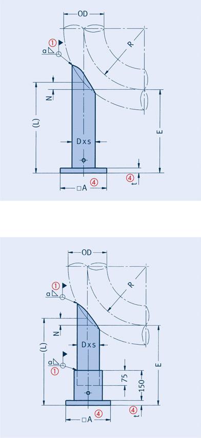
Type 58 .. 25 Type 58 .. 26
Example: Stanchion for long radius elbow radius R 1.5 OD, OD = 419mm, E = 750mm (as anchor).
Stanchion length: L = E+N (see data in selection table), L = 750mm +75mm = 825mm.
For stanchion D = 139.7mm (designation ‘f’). Permissible load = 0.37 x 22.5kN (see table on page 5.15) = 8.3kN. ... See page 5.15.
Order details: stanchion for long radius elbows R 1.5 OD type 58 , E = ...mm
Field weld
The weld seam stress amounts to max 50N/mm2 for the specified weld seam thickness and permissible loads
Type designation:
58 .. 1. stanchion
58 .. 2. telescopic stanchion
Table data A x t
The permissible loading of the stanchion in dependence on length can be found in the diagram.
Max lateral loading of stanchion = 100% of specified vertical load
For welding designs of this type, the load transmission to the piping, and observing the allowable stress of the pipes must be guaranteed by the user.
Materials:
base plate S235JR S355J2 stanchion P235GH
Surface protection: weldable primer
Permissible load in dependence on length of stanchion for slide bearing or fixed point
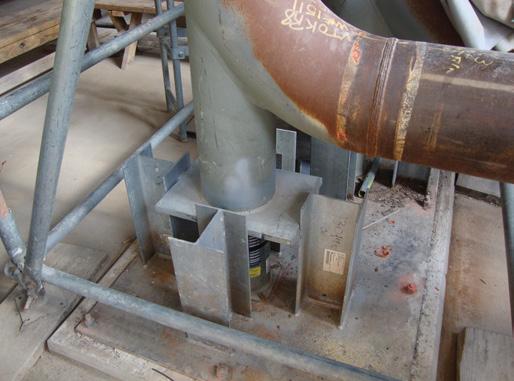
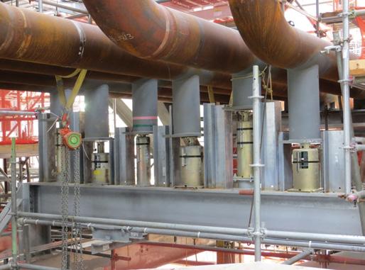
ProducT 6 grouP
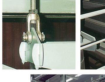
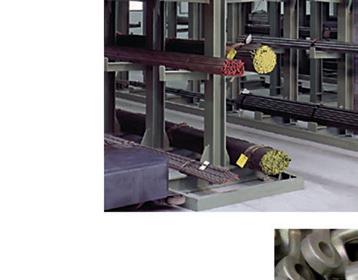
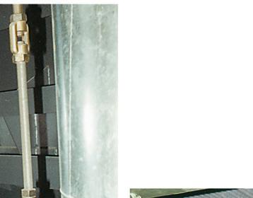
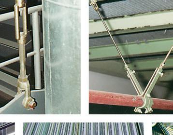
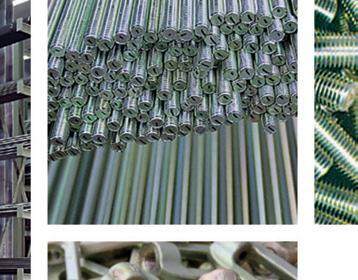
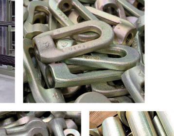
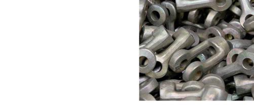
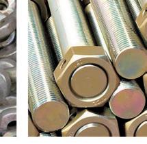
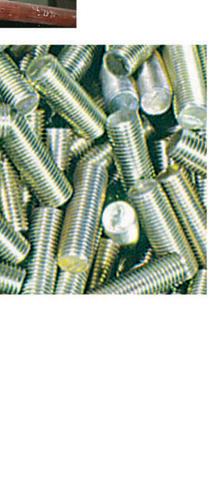
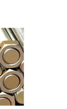
Precision-fit threads, reliable material properties and design with sufficient load reserves are prerequisites for the reliability of the whole load chain.
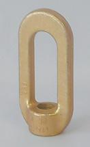
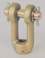
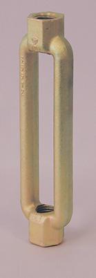
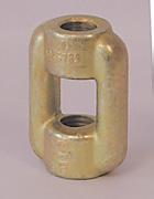
The connections in product group 6 are specially shaped bolting components to attach the connecting rods to other support components. They connect components in the load chains with their counterparts, such as lugs, clevis or eye plates.
The connections in product group 6 form an independent group within the modular system and were specially designed for optimum use as pipe support components.
They are largely drop forged and, except for turnbuckle type 62, so designed that they enable a little length regulation despite low installation heights.
The permissible loads correspond to the load tables for statically determined components on page 0.6 of the technical specifications.
Eye nut type 60 is used as a transition from a rod to a pin connection; threaded clevis with pin type 61 joins a rod to a lug connection.
Turnbuckle type 62 is fitted with a right-hand thread on one side and a left-hand thread on the other. It is used in combination with tie rod type 65 for length regulation and the pre-stressing of load chains.
If required, rod coupling type 64 is used to form rod lengths longer than 12 foot [3.66m].
All threads (except in turnbuckle type 62) are right-hand and available in both UNC and metric versions.
For corrosion protection the components are electro galvanized as standard, coating thickness approximately 0.47 – 0.59 mil [12-15µm]. For use in particularly aggressive atmospheres hot dip galvanized components can be supplied.
If required, the components can be supplied with material certificates.
It is often necessary to use the connection components in areas above the standard field of application, where higher temperatures apply.
The LISEGA connections offer special benefits: universal application possibilities load and connection compatibility with the LISEGA modular system drop forged and heat-treated electro galvanized as standard, hot-dip galvanized if required approval through special type tests
For this, LISEGA SE offers products made from the material 10CrMo9-10 for the connection to special designs (see page 4.9). The upper load limits for use up to 500°C corresponds to the nominal load (see chapter 4.1.1 on page 0.5) of the respective load groups. The type numbers are described as follows:
Eye nuts : 60 .9 04-HT; (60 D9 04-HT to 60 99 04-HT)
Threaded clevises with pin : 61 .9 04-HT; (61 D9 04-HT to 61 99 04-HT)
Turnbuckles : 62 .9 04-HT; (62 D9 04-HT to 62 99 04-HT)
Rod couplings : 64 .9 04-HT; (64 D9 04-HT to 64 99 04-HT)
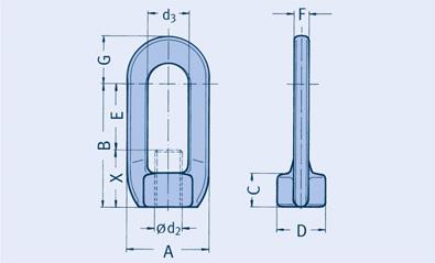
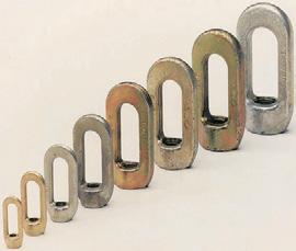
60 D9 19 24401117M101325 5 15 150.05
60 29 12 33601524M121740 6 19200.10
60 39 12 44752030M1625451026300.20
60 49 12 59902535M2029551035350.40
60 59 12 721103044M2435651544450.80
60 69 12 881273750M3042751754521.20
60 79 12 1001404560M3647752062652.00
60 89 12 1101575270M4252852572722.90
60 99 12 1201806080M4862853078954.70
60 10 12 1352006595M56x4621054080957.70
60 20 12 15023070105M64x47213040851008.80
60 30 12 16023070110M68x47213040901009.30
60 40 12 220250120125M72x4821005011015027.00
60 50 12 250280140140M80x4921206012516045.00
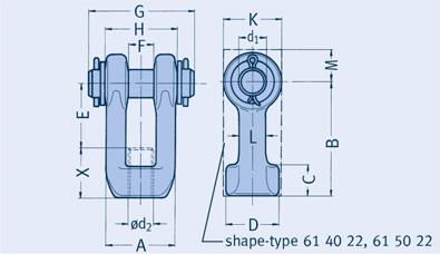
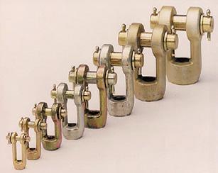
61 D9 19 2350111710M1035115025215x9
61 29 12 3370152512M1250126034248x12
39 12 4280203316M16501770443211x15
61 49 12 5590254020M20552090574616x21
61 59 12 65110304624M246522105685319x25
69 12 72130355133M308027125806419x29
Eye nuts type 60 D9 19 to 60 50 12
Material: P250GH drop forged.
From load group 40 welded design material: S355J2.
Order details: eye nut type 60..1.
Threaded clevises with pin type 61 D9 19 to 61 50 12
Material: P250GH
From load group 10 and further material: S355J2, drop forged.
From load group 40 and further flame cut design material: S355J2.
Pins
C35E+QT complete with cotter pin DIN EN ISO 1234 and washers DIN 1441.
From load group 40 and further material: S355J2.
Order details: threaded clevis with pin type 61..1.
S235JR drop forged. From load group 10 flame cut design material: S355J2.
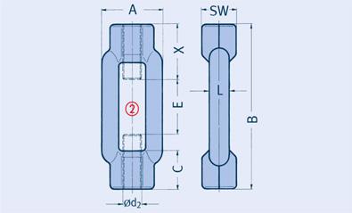
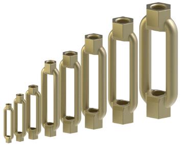
One side right-hand, other side left-hand thread.
The ends of the threaded rods must not come into contact.
Order details: turnbuckle type 62..1.
Rod couplings type 64 D9 19 to 64 50 15
Material: S235JR drop forged.
From load group 10 flame cut design material: S355J2.
62
62
Order details: rod coupling type 64 .. 1.
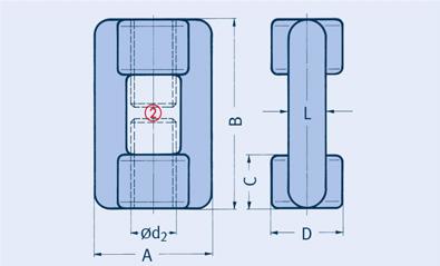
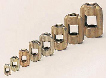
64
Threaded and tie rods connect the support components to each other in order to bridge installation heights. They can be used as rigid supports with the connection components and in elastic load chains with spring and constant hangers.
Only materials with guaranteed mechanical properties regarding good homogeneity and sufficient charpy-test values (ductility) are used. The permissible loads correspond to the load table for statically determined components in the technical specifications on page 0.6.
All threads are manufactured in a rolling process. By rolling the threads are not cut. Through the rolling process the material is made to flow and is plastically formed. In this way the surface is given additional notch-free high-quality strength.
Friction resistance is thereby reduced; this has a favorable effect on any adjustment of the rods under load. On top of that, safety reserves exceeding the demands of the design specifications are created.
Threaded rods type 67 with continuous threading up to M48 and tie rods type 66 (from M20) are available in fixed 500mm length increments in the length range from 500mm up to 3,000mm. The tie rods have thread lengths of 300mm on one side and 600mm on the other. The short thread is for length adjustment, e.g. as a connection for spring and constant hangers. The long thread is for the fitted length. This can be shortened as required according to the installation height on site.
Larger tolerances in the building structure have led to increasing problems with fitted lengths instead of easier installation, especially when the connection threads are too short. The use of standardized fixed lengths is therefore more and more common because of their greater flexibility. Fitting can be easily carried out with hanging rods already mounted at the upper end.
Laborious measurement with the risk of error is thereby avoided. Structural tolerances can be compensated for.
Tie rods type 65 with right-hand / left-hand threads are always used in combination with turnbuckle type 62 and fitted with standard lengths. They are designed for length adjustment and force-fit prestressing of load chains.
All other bolted connections are exclusively right-hand threads and on installation must be locked with a hexagon nut type 63.
For corrosion protection all rod types are electro galvanized, layer thickness approx. 12-15µm. If required, hot-dip galvanization is available.
Hot dip galvanized threaded rods M10/M12 are available in lengths up to 1,000mm. Longer length can be prepared by rod couplings.
If required, all components can be supplied with certificates according to DIN EN 10204-2.2 or 3.1.
materials with proven characteristics rolled threads notch-free surfaces electro galvanized surfaces standard lengths in-house manufacture
Often there is a need to use the connecting members even in areas which are above the standard range of application and can exposed to with higher temperatures. For this LISEGA SE offers products made from the material 21CrMoV57 or 25CrMo4 for hex nuts for the connection to special designs (see page 4.9). The load limits for use up to 500°C correspond to the nominal load of each load groups.
The type numbers are described as follows:
Tie rod L/R : 65 .1 03-HT; (65 D1 03-HT to 65 91 03-HT)
Stud bolt : 67 .1 03-HT; (67 D1 03-HT to 67 91 03-HT)
Threaded rod : 67 .. 03-HT; (67 D2 03-HT to 67 95 03-HT)
Tie rod : 66 .. 03-HT; (66 46 03-HT to 66 97 03-HT)
Hexagon nut : 63 .9 3. ; (63 D9 39 and 63 19 38 to 63 99 38)
The pipe systems are embedded in load chains, where the connecting rods are important elements. When selecting them great attention must be paid to quality so that these seemingly simple components do not form the weakest link in the chain. The decisive factors for their load-bearing capacity are, beside adequate dimensioning, material quality and design conforming to standards.
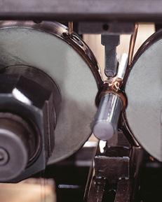
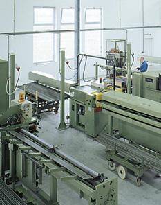
Manufacture of threaded components
Fiber flow of rolled thread
Tie rods left-hand/right-hand type 65 D1 19 to 65 50 13
Material: M10 to M16: S235JR from M20: S355J2.
LISEGA threaded rods should only be replaced in kind.
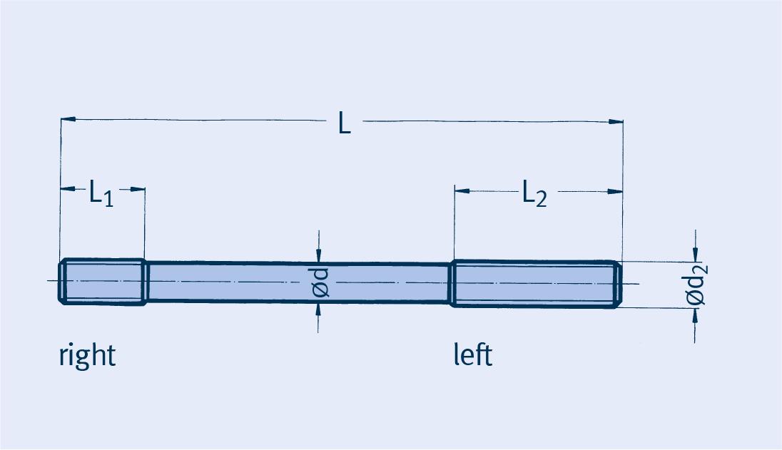
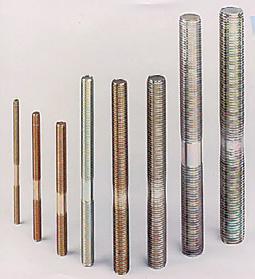
Order details: tie rod L/R type 65..1.
Hexagon nuts type 63 D9 29 to 63 50 28
Material: grade 8 hexagon nuts DIN EN ISO 4032 as counter nuts for threaded rods M10 – M80x4.
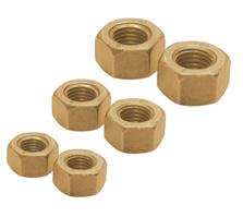
Stud bolts type 67 D1 19 to 67 91 13
Material: M10 to M16: S235JR from M20: S355J2.
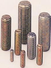
Order details: hexagon nut type 63..2.
Order details: stud bolt type 67..1.
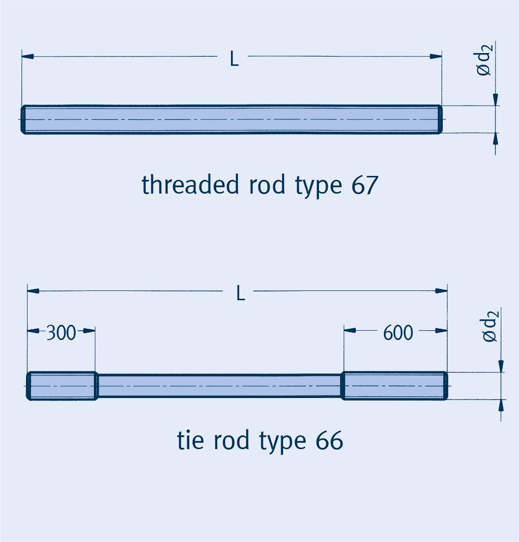
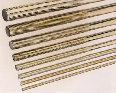
Threaded rods / tie rods type 67 D2 19 to 67 50 13 / type 66 46 13 to 66 50 13
Material: M10 to M16: S235JR from M20: S355J2.
LISEGA threaded rods should only be replaced in kind.
M
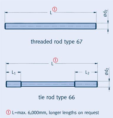
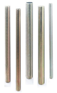
Standard lengths avoid problems caused when installation lengths are too short. They can be flexibly adapted by shortening to suit the installation situation on site.
Order details: threaded rod / tie rod type 6. .. ..
Connecting rods from M56x4 can be supplied as threaded rods type 67 or as tie rods type 66 with individual rolled thread lengths.
Order details: from M56x4: threaded rod / tie rod type 6. .. .. L = …mm L1 = …mm L2 = …mm
ProducT 7 grouP
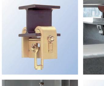
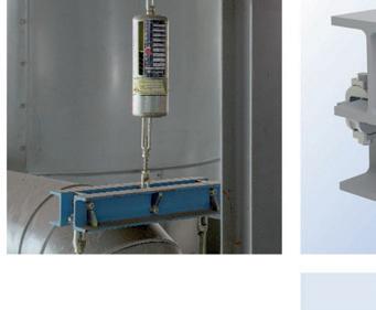
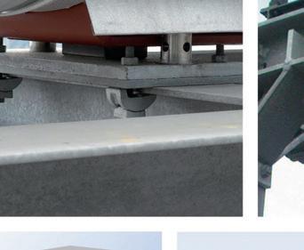
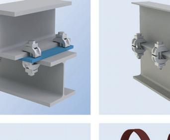
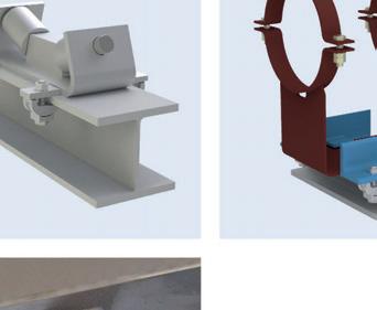
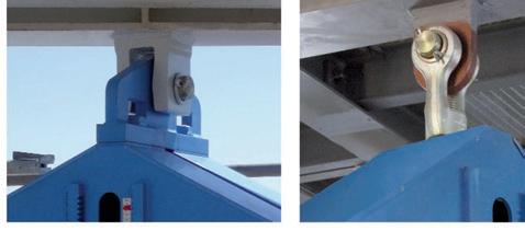
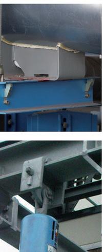
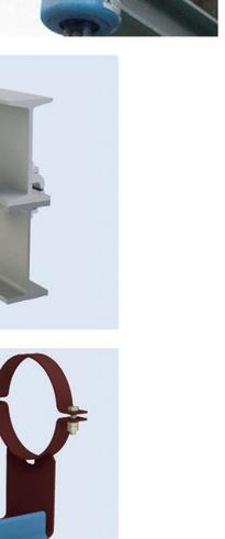
Special components for welding or clamping are available for connecting the pipe supports to the supporting structure. In order to fulfill safety requirements the connections must be suitable.
Connecting components for the direct attachment to the structure and trapezes form part of product group 7.
The permissible loads for the components correspond to the load table for statically determined components in the ‘technical specifications’, page 0.6.
For weld-on clevises type 73 – well suited for connection to hollow sections - and weld-on eye plates type 75 the specified minimum weld seam thicknesses must be taken into account. These are calculated not to exceed a maximum weld seam stress of 75N/mm2 (load case H / level A/B). An angulation of up to 6° was considered in the basis of the load calculation.
The weld-on plates type 74 enable use of the maximum pendulum length in restricted spaces by means of a plug connection. Here too, an angulation of up to 6° was considered in the basis of the load calculation.
The hot dip galvanized beam adapters type 76 allow clamp connections instead of welded connections, for example at extensions of piping systems or steel structures in existing plants.
Beam clamps type 78 are designed for weld-free connection on site. They are suitable for all beam widths and flange slopes. When ordering, please state beam widths and flange thicknesses.
For protection against corrosion the components are given a weldable primer coating (30µm) or are electro galvanized (layer thickness 12 - 15µm).
Trapezes type 79 are for the attachment of clamp bases type 49 and type 56 and can be used for rigid suspension as well as for connection with spring and constant hangers.
The trapeze profiles are protected against corrosion according to LISEGA standard color coating (see page 0.10).
All components can on request be supplied with material certifications.
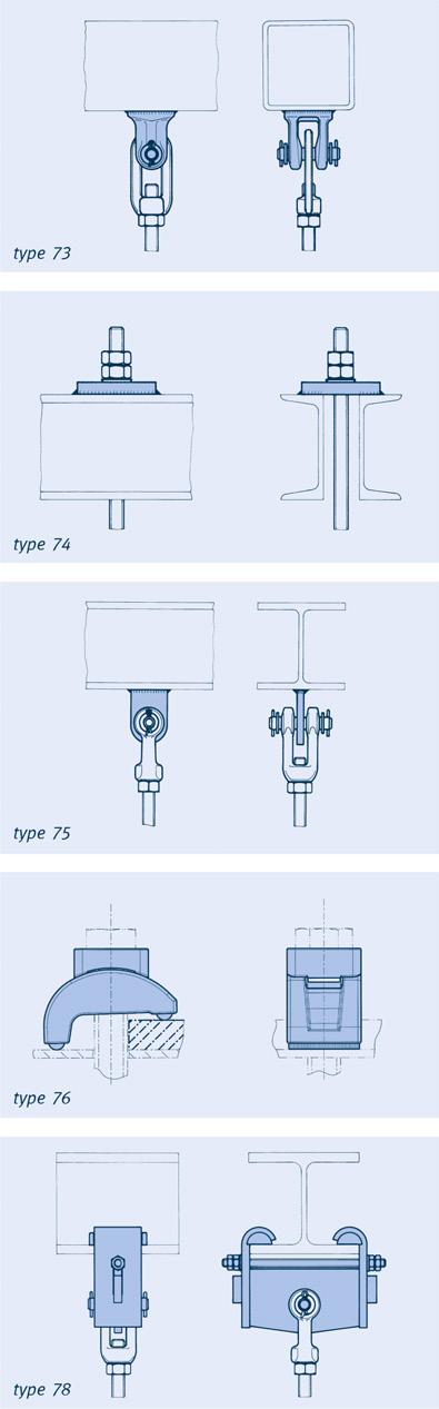
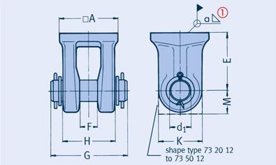
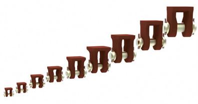
73 29 1340123512603424–3.00.3 73 39 1350164017704432–3.00.4 73 49 1365205020905746–3.01.1 73 59 13752460221056853–3.02.1 73 69 12953390271258064–3.53.8
73 79 1212040110321409380–4.06.8
73 89 12120451203716511090–5.59.2
73 99 121205013042185120100–7.511.1
73 10 121506014050210150120–8.518.5
73 20 12170x1757015060245165170759.037.0
73 30 12170x17570150602451651707510.537.0
73 40 12150x19080170562301501509012.538.0
73 50 12180x220901956424016518011013.558.0
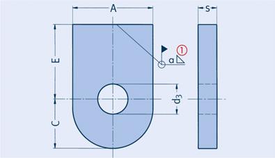
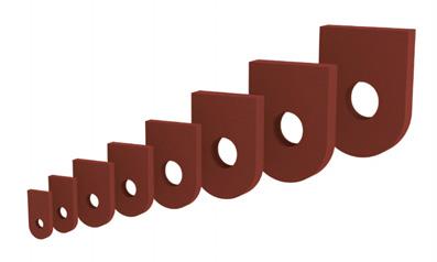
Weld-on clevises type 73 29 13 to 73 50 12
Material: S355J2 drop forged.
From load group 20: flame cut design made of S355J2. pin: C35E+QT.
Calculation of the weld seams was based on a permissible stress of 75N/mm2 in load case H (level A/B).
Order details: weld-on clevis 73 .. 1.
Weld-on eye plates type 75 D1 19 to 75 50 12
Material: S235JR From load group 6: S355J2
75
75 30 12180 71130110
75
75
Calculation of the weld seams was based on a permissible stress of 75 N/mm2 in load case H (level A/B).
Order details: weld-on eye plate type 75 .. 1.
Weld-on plates with spherical washer type 74 D1 19 to 74 50 13
Material spherical washer: case-hardened steel. From load group 5: C15. weld-on plate: S235JR. For s 20: S355J2.
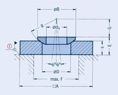
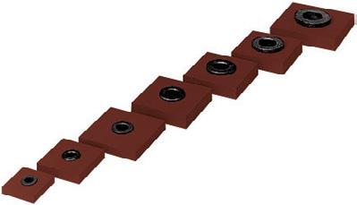
LISEGA recommends tack welding of the weld-on plate for fixing positions or welding all round as specified.
Order details: weld-on plate with spherical washer type 74 .. 1.
74 62 13M3017056453135602741306.8
74 71 13M3613068503737703250304.0
74 72 13M3617068503737703250306.8
74 81 13M4213078594339903758304.0
74 82 13M4217078594339903758306.8
74 91 13M48130926650461204167354.5
74 92 13M48170926650411204167306.8
74 10 13M56x422510376584714050793513.9
74 20 13M64x425012089665415059934019.6
74 30 13M68x4250128957061160641004522.0
74 40 13M72x4300136987561160701074531.8
74 50 13M80x43501521108364180781204543.3
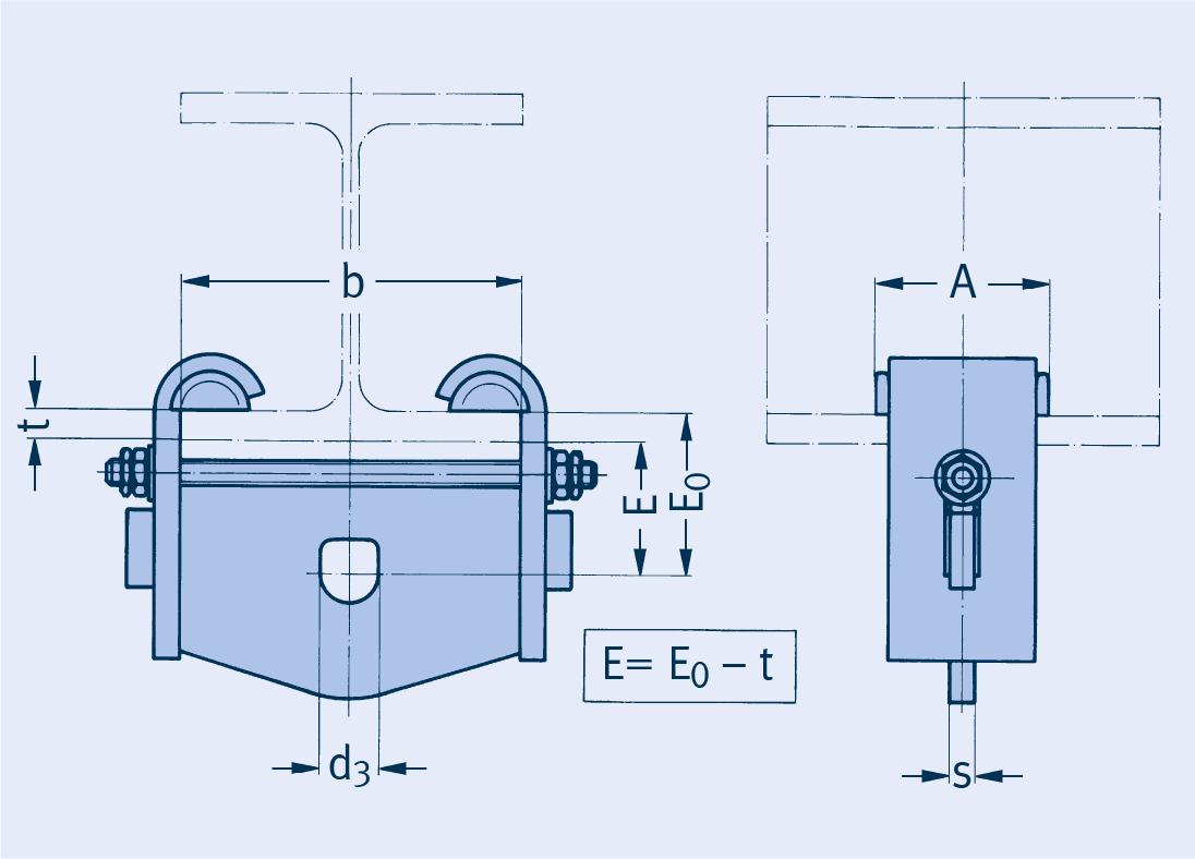
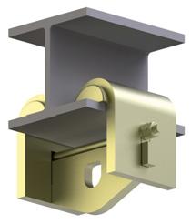
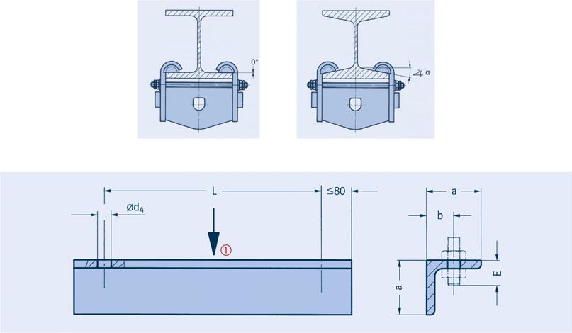
Trägerklammern
Typ 78 21 11 bis 78 71 11
Surface: electro galvanized
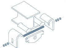
Load sizes 8 + 9 can also be connected. The permissible load amounts to 100kN in load case H (level A/B).
Larger ‘t’ dimension possible on request – E0 increases correspondingly. When ordering please state beam width ‘b’ and flange thickness ‘t’.
Order details: beam clamp type 78 .1 11 beam width b = …mm flange thickness t = …mm
Trapezes for the use of lower loads at temperatures 80°C type 79 C2 37 to 79 42 37
The permissible center load is to be taken from the respective trapeze load group (3rd digit in the type designation).
Order details: trapeze type 79 .2 37, L = …mm
Trapezes
type 79 22 34 to 79 20 34
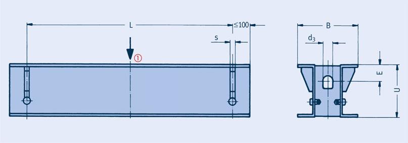
The permissible center load is to be taken from the respective trapeze load group (3rd digit or 3rd and 4th digits in the type designation).
The Lmax dimensions can be lengthened up to 2400mm on load reduction of 5% per 100mm extension.
Connection possible for the specified load groups.
Order details: trapeze
type 79 .. 34, L = …mm
Trapezes
type 79 23 39 to 79 93 39
The permissible load for the middle connection is to be taken from the respective trapeze load group (3rd digit in the type designation).
Lmax can be lengthened to 2400mm for type 79 23 39 to 79 73 39 on reduction of the permissible load by 5% for every 100mm.
Connection possible for the specified load groups.
Order details: trapeze
type 79 .3 39, L = …mm
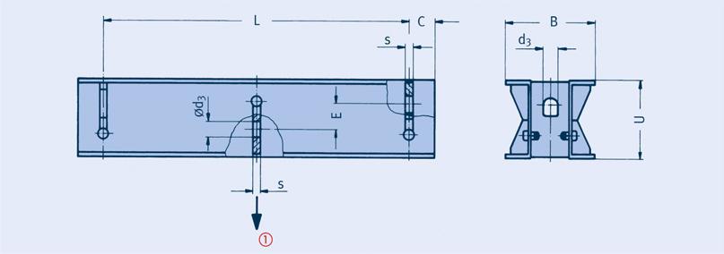
On alterations or extensions of the pipe systems or steelwork in existing plants, clamp connections are frequently preferred to welded connections. Clamp connections are strictly specified in cases where welding connections are excluded for safety reasons.
The safety of the clamping effect of such connections depends essentially on the nature of the existing contact surfaces and the prestressing forces applied. The design of the clamping components used is therefore decisive for a reliable connection.
For the creation of safe and reliable clamp connections LISEGA offers the beam adapter system type 76. These components enable the connection of very different components to existing steelwork without welding or drilling.
Assembly is simple and timesaving. On tightening, LISEGA beam adapters adjust independently to the existing beam thickness.
If the specified tightening torques are observed, lasting security of the connections is guaranteed. Any corrosion protection already present, such as hot-dip galvanization or paint coatings, incurs no damage.
The special support segments are the main feature of the LISEGA beam adapters. Due to their shape they automatically adapt to any position and to existing profile angles.
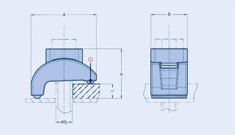
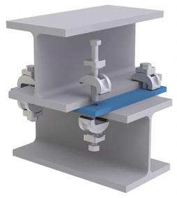
Material: cast iron hot dip galvanized
The loads specified correspond to this in load case H (level A/B) ‘Max. permissible loads’ page 0.6. For further load cases see table. Friction value µ = 0.14.
Order details: beam adapter (without bolt) type 76 .. 11 bolts for beam adapters, see page 7.7.
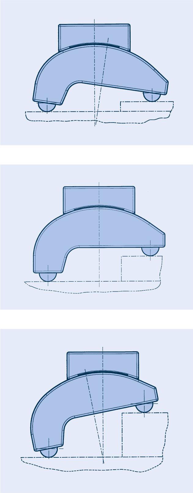
Typical utilization of beam clamps at different material thicknesses
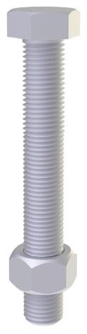
Order details: bolt for beam adapter type 76 .2 11- …
The hardened support segments have a circular groove profile that is pressed into the contact surface on tightening. This way, a form-fit contact is produced which ensures that no shifting in any direction takes place.
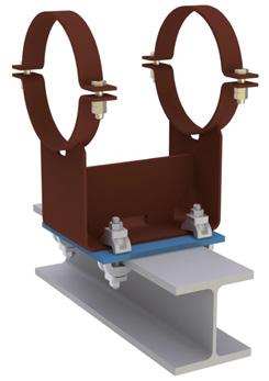
Example of use: Attachment of clamp base to steel beam
Bolts for beam adapters
Cross-connection
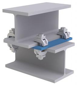
The safe connection of beam profiles to each other is produced very easily with an inlay plate and 8 LISEGA beam adapters. The load-bearing capacity of a cross-connection can be found in the table below.
Hexagon bolts DIN EN ISO 4017, thread to head, grade 8.8, hot dip galvanized, including a hexagon nut DIN EN ISO 4032, grade 8, hot dip galvanized.
Load-bearing capacity of cross-connections with LISEGA beam adapters
Profile connection
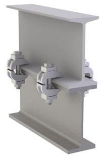
The connection of profiles to each other can be made either directly or by using an inlay plate.
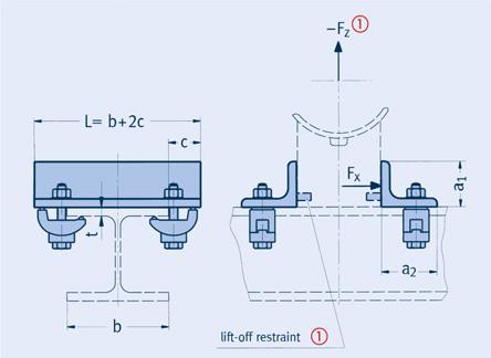
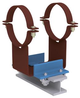
If required, the guides can be supplied with an additional lift-off restraint (width 80mm).
(When ordering also specify clamp base type.)
Fz: the permissible short duration lift-off load is limited in every case by the permissible lift-off load of the clamp base. See page 4.68 for this.
Friction value µ = 0.14
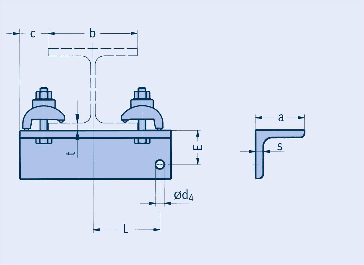
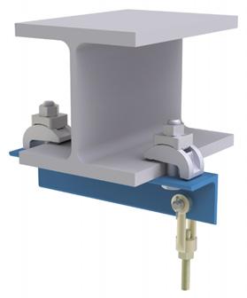
Guide with beam adapters for clamp bases type 76 00 11 to 76 00 14
Material: guide S235JR
Order details: lateral guide type 76 00 1., b = …mm
Order details: lateral guide with lift-off restraint type 76 00 2. – 49 .. .. (clamp base type), b = …mm
Cantilever with beam adapters type 76 C1 16 to 76 21 16
Material: cantilever S235JR
Friction value µ = 0.14
Order details: cantilever with beam adapters type 76 .1 16 b = …mm, L = …mm
Cantilevers with beam adapters types 76 C1 17 to 76 21 17
Material: cantilever S235JR
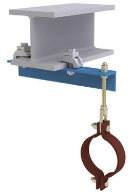
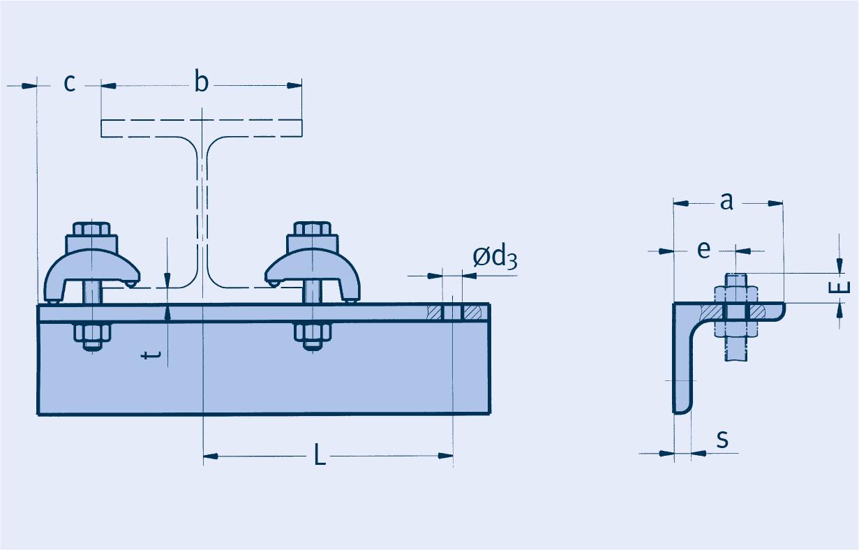
value µ = 0.14
Order details: cantilever with beam adapters type 76 .1 17 b = …mm, L = …mm
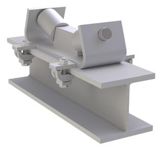
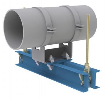
The pipe systems resting on pipe bearings are subject to displacement as a result of thermal expansion. This displacement must be permitted to prevent unacceptable stresses that could damage the piping system. Furthermore, the slight friction caused by these movements is reduced by inserting slide plates between the clamp base and supporting framework.
During the planning phase the reduction of friction forces is extremely important. Since friction forces can represent considerable additional forces to the operational loads, they are usually distributed into the supporting framework (building structure or secondary steelwork) by the use of low friction materials/surfaces.
By lowering friction forces the dimensioning of building structures and secondary steelwork can be, under the aspect of cost saving, reduced. Also the reaction forces in the pipe statics.
Slide plates are commonly used in all pipe systems in industrial processes / chemical plants, in the power station field, in liquefied gas transport or in district heating pipe systems.
Through the use of slide plates friction forces can be reduced about 60%. Instead of steel / steel sliding contact with a friction coefficient of µ 0.3, through the use of slide plates and a stainless steel plate as a counterface on the clamp base side the friction coefficient can be reduced to as little as µ 0.1 (dry).
LISEGA slide plates consist of different low-friction materials for different temperature ranges. For use at a constant temperature up to 180°C (at the bottom of the clamp base) the standard PTFE slide plate is recommended. For temperatures above 180°C to a maximum of 350°C a special high-temperature material is used.
high mechanical wear resistance
temperature resistance up to 350°C suitable for use in aggressive environmental conditions due to their high chemical resistance self-lubricating permanent freedom from maintenance long lifespan
excellent load-bearing capacity
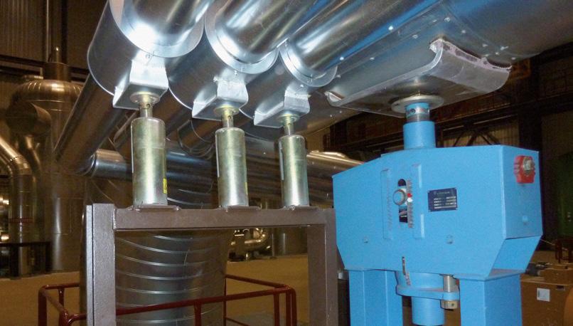
Clamp bases are seated on slide plates allowing movement with reduced friction – this means the pipe systems can move without constraint during thermal expansion.
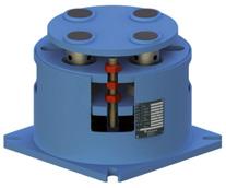
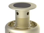
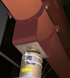
Other fields of application for LISEGA slide plates are uses where heavy loads must be moved horizontally. By using slide plates the force required for movement can be reduced by as much as 60%. The use of slide plates has a favorable effect on the whole pipe system layout.
LISEGA slide plates for the temperature range up to 180°C are made of the low-friction material PTFE. For temperatures from 180°C up to 350°C a special high-temperature material is used that not only increases heat resistance but also optimizes the mechanical properties.
The LISEGA slide plate to weld on consists basically of a supporting plate of carbon steel with a weldable primer coating in which the low-friction material is embedded.
Optionally these supporting plates can be supplied hot dip galvanized.
The LISEGA slide plates for bolting are hot dip galvanized as standard.
The counterface is a stainless steel plate. Optionally the stainless steel plate, that must be ordered separately, can be welded to carbon steel support plate or it is attached to the bottom of the clamp base in the factory and can be used immediately.
Specially developed for vertical installation, such as for example for type 49 .. .. G.. pipe guides, the slide plate is bolted to the support plate.
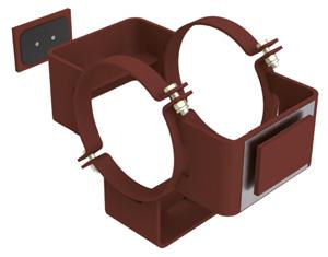
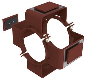
Parallel installation of the slide plates and counterfaces is required.
In every possible bearing position the slide plates must be fully covered by the counterfaces.
The components are to be fitted so that any bending of the slide plates or counterfaces is prevented.
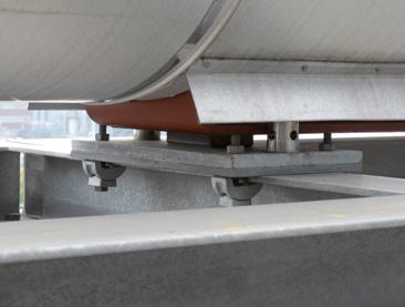
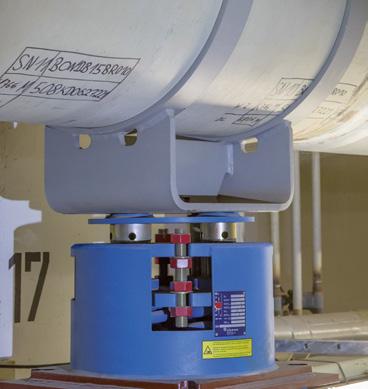
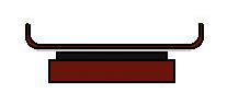
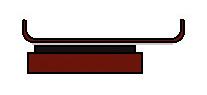
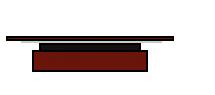
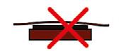
Type 70 .. 1. Is tack-welded with single datum points. If all-round welding is required, the temperature of the PTFE material must not hereby exceed 260°C. When welding, the PTFE material or the restraining surfaces of the support plate must be protected from dirt.
It is recommended to install the slide plates only horizontally. For vertical installation type 70 .. ..-MB is to be used. When it has been ensured that the counterface is always in contact with the PTFE, the standard component shape 70 .. .. can also be used.
Type 70 .. 2. and type 70 .. 3. are bolted to the steelwork with M10 or M12 cylinder bolts. These bolts do not form part of the scope of supply.
Special sizes can be supplied on request.
Slide plates to weld-on (rectangular shape)
type 70 11 1. to 70 48 1.
Material: S235JR
Surface: weldable primer
The 6th digit is to be filled out in dependence of the operating temperature.
For friction values of slide plates: see table on page 7.11.
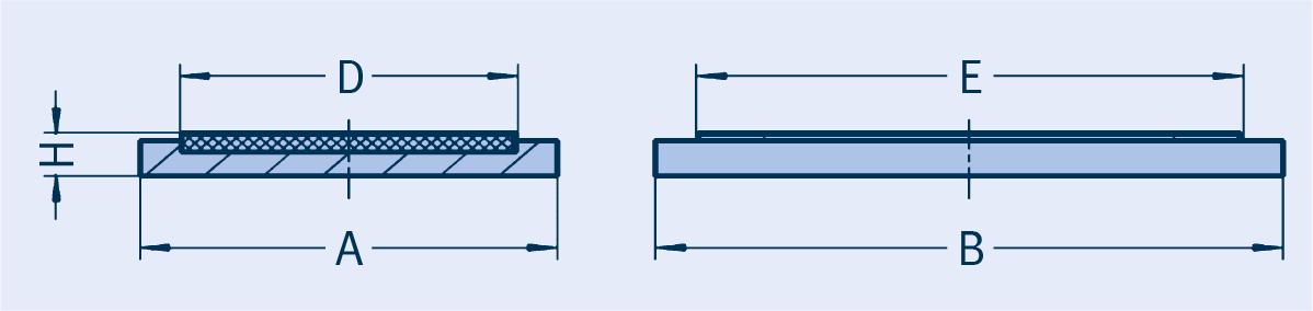
slide plate to weld-on type 70 .. 1.
Slide plates to weld-on (round shape) type 70 05 1. to 70 20 1.
Material: S235JR
Surface: weldable primer
The 6th digit is to be filled out in dependence of the operating temperature.
For friction values of slide plates: see table on page 7.11.
Order details: slide plate to weld-on type 70 .. 1.
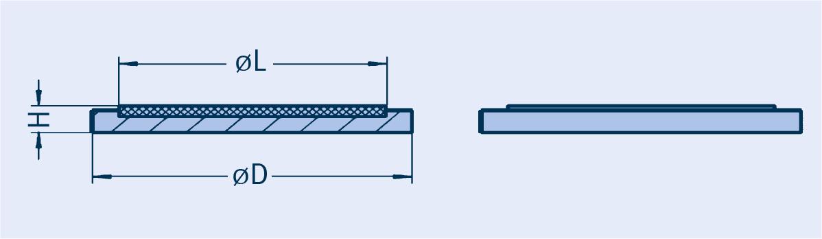
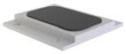
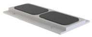
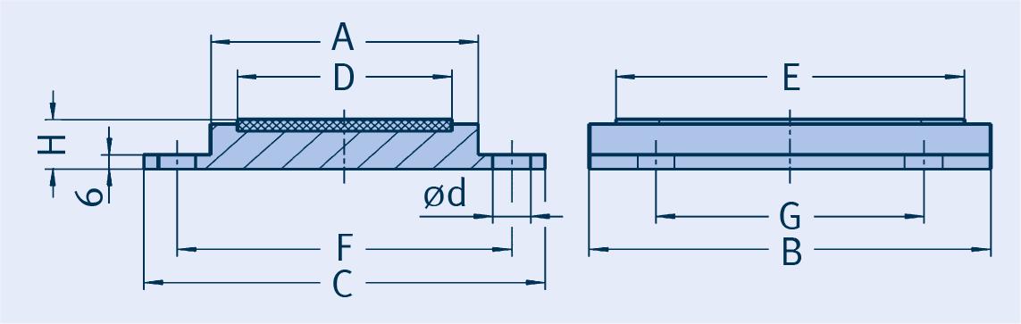
Slide plates for bolting (rectangular shape lengthwise)
type 70 11 2. to 70 48 2.
Surface: hot dip galvanized
The 6th digit is to be filled out in dependence of the operating temperature.
x 1802001751504144.7 70 36 2.35821672015030022130 x 2802001752504147.0 70 37 2.465276920150390222 x 130 x 1802001753004149.1 70 38 2.5953541180150490222
2.498300100020030022180
70
70
70
Order details: slide plate for bolting type 70 .. 2.
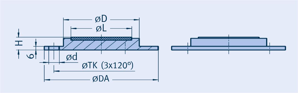
Slide plates for bolting (round shape)
type 70 05 2. to 70 20 2.
Surface: hot dip galvanized
The 6th digit is to be filled out in dependence of the operating temperature.
Order details: slide plate for bolting type 70 .. 2.
Slide plates for bolting (transverse rectangular shape) type 70 12 3. to 70 48 3.
Surface: hot dip galvanized
The 6th digit is to be filled out in dependence of the operating temperature.
For friction values of slide plates: see table on page 7.11.
Order details: slide plate for bolting type 70 .. 3.
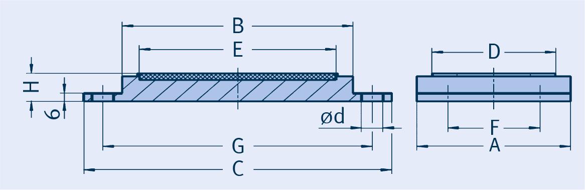
Material: S235JR
Surface: weldable primer
Supplementary order details: slide plate 70 .. ..-MB

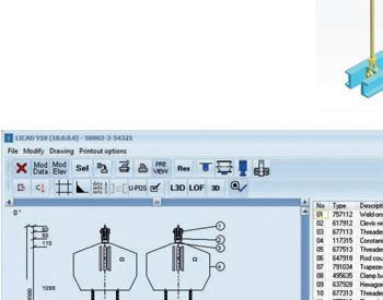
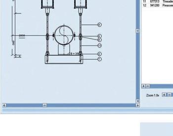
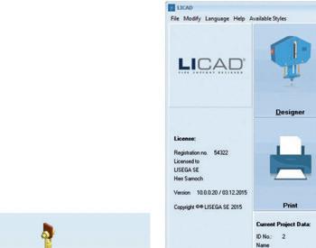
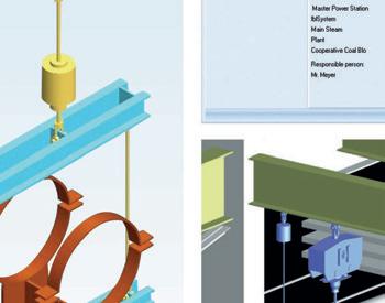
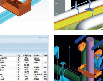
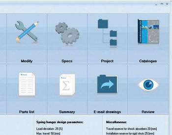

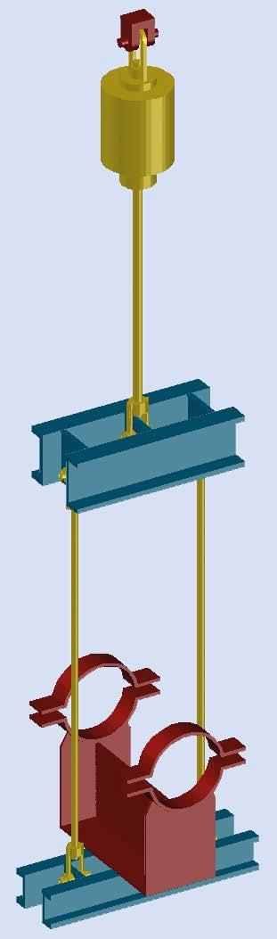
intelligent solution for support design
LISEGA’s unique modular system was the prerequisite for the creation of highly sophisticated user software. The solutions we offer open up new opportunities for increased efficiency in design, optimized quality and significant savings in project man-hours.
In general, the model design of plants is carried out with CAD, including CAE systems. Through the integration of LICAD® into different CAD systems, the benefits for the efficient layout of piping systems have been vastly improved.
The LICAD® program has set new standards in this field. It enables the creation of support drawings and lists of materials in minutes instead of hours. LICAD® is an intelligent frontend program that supplies the necessary interface data from only one source for all CAD programs currently in use.
From the point of view of quality this single-source function is particularly important.
To provide the LICAD® user with the widest possible range of applications, LISEGA has developed supplementary user software. The whole package covers:

LICAD® is a registered trademark of LISEGA SE. All other products, fonts and company names are trade names or registered trade names of the respective companies.

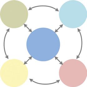





LICAD® planning and design program for pipe supports
Interfaces for import and export of tables and databases
Interfaces with 3D-CAD component packages
2D / 3D libraries for different CAD programs
Internet communication system for downloading the latest program versions and information on projects, including drawings and orders
Interface to stress analysis and steelwork software
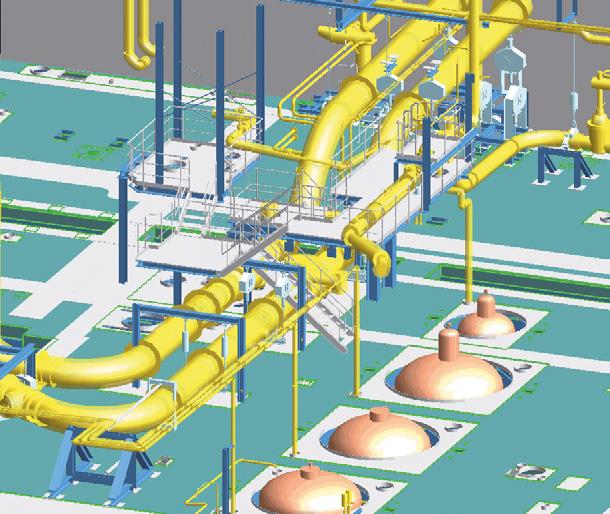
As a rule the project planning of complex pipe systems runs through numerous phases of optimization. The design of pipe supports inevitably takes place at the end of the whole process and so their deployment frequently comes far too late. Although the supports are needed on site beforehand for optimum installation of the pipe systems, they lie right at the end of the planning chain - all the more important to avoid unnecessary delay. The time factor is now crucial.
LICAD® speeds up the planning process
LICAD®, the LISEGA design program for pipe supports, sets the highest standards in efficiency. With LICAD the laborious poring over catalogs and the paintaking preparation of lists of material are a things of the past. Support designs and load chains no longer need to be manually configured and then drawn up at great expense and effort. What would otherwise take hours to produce can be done by computer in minutes –at the click of a mouse!

With LICAD®, great savings in time are possible in the logistics process, from planning right through to delivery. For example, the LICAD® data can, if required, be transmitted directly for processing on the same day by e-mail as a computerized order list. This fits in perfectly with ever-tighter order deadlines.
The downloading and use of LICAD® is free of charge.
In the current version the following languages are available for menu navigation and print editions: Chinese, German, English, French, Italian, Japanese, Polish, Portuguese, Russian, Spanish and Hungarian.
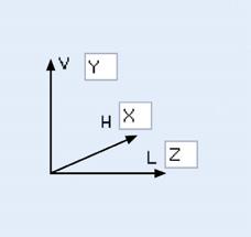
The relevant data for industrial support points is entered using menu-driven program control. Only 6 parameters are needed to find the optimum solution.
pipe diameter temperature of medium operating load displacement installation height support configuration
From this input, the appropriate load chains are automatically generated. The selection of optimum spring and constant hangers thereby follows automatically, whereby the specific customer requirements such as, for example, travel and load
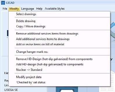
reserves according to ASME B 31.1, VGB-R 510 L, DIN EN 13480 or other optimum parameters are taken into account. This is ensured by the corresponding entries in the options menu.
Taking this information into account, LICAD’s programmed algorithm chooses the most economical solution.
The support chains created are automatically saved as complete assemblies and can be printed out as drawings or modified at any time. They are true to scale and contain all relevant details, including parts lists with weights and materials and optionally with location plan or other freely editable information.
The basis of the program is a database system in which the whole LISEGA standard product program is stored as a modular system of absolute functionality. From more than 12,000 standard components, all fully compatible regarding loads and connections, more than 100 standard configurations cover practically all normal installation situations.
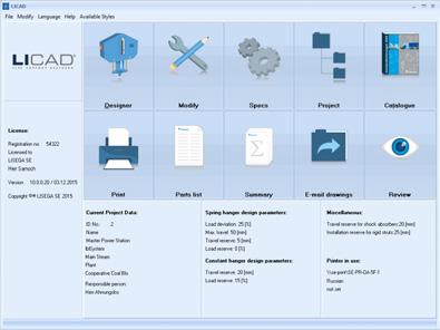
All essential functions at a glance
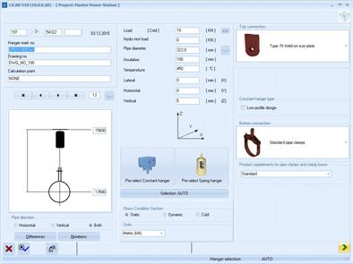

Support design with detailed parts list
LICAD® generates ready-to-install load chains from standard supports, from structural attachment to pipe-surrounding component. More or less complex auxiliary designs are necessary for connection to the existing structures (secondary steelwork).
Through its special interface the LICAD® designs can be exported into a separate CAD program (e.g. AutoCAD®, MicroStation®) and supplemented as required.
For larger plant projects the design of the building structure, including steelwork, main components and connecting piping system, is carried out via 3D CAD programs such as
Smart™ 3D (Intergraph), PlantSpace (Bentley Systems), Plant 3D (AutoDESK) or PDMS™ (AVEVA). Planning continuity, as well as the need to consider possible interference, make it necessary to fully include the pipe supports.
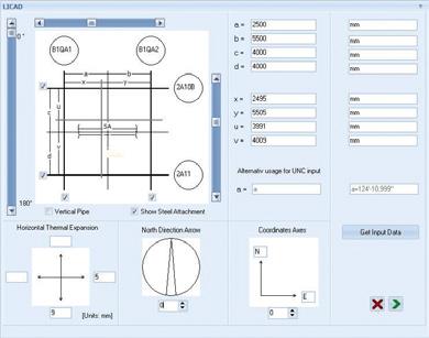
Location plan with axis designations and dimensioning LICAD®
LICAD® runs smoothly on any modern PC with Windows and is easy to use. Due to its particular effectiveness LICAD® has long been an indispensable tool in support planning for countless engineering offices. Potential savings in costs of up to 50% simply cannot be ignored!
LICAD® contains a wide range of interfaces and component libraries for well-known CAE, CAD and steelwork programs.
This benefits resources and makes for significant savings in time when designing pipe systems!
A broad spectrum of interfaces enable the import and export of data already entered from, and to, CAD and CAE systems.
This basis of the selection of a support chain is formed by the design data from the pipe calculations of the pipe system. One of the CAE systems is the ROHR2 ® program system (Sigma Co.), which is used for the static and dynamic analysis of complex piping systems and common skeletal structures.
The interfaces to the CAE systems mentioned above are part of the basic LICAD® package. Optional interfaces for downloading can be found on the LISEGA homepage.
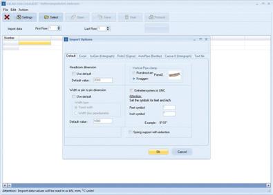

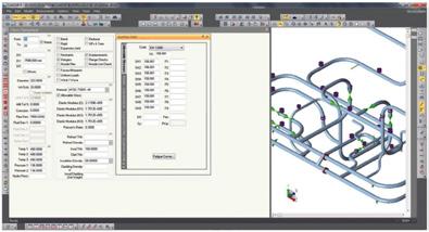
Data from AutoPIPE ® (Bentley systems) or CAESAR II ® (Intergraph Co.) can continue to be included and used in the selection of the appropriate supports. The data gained from the CAE systems can be sent directly to CAD programs after generation of the supports.
This procedure enables a considerable increase in efficiency and savings in time when designing complex pipe systems.
Via defined interfaces the LICAD® support designs can be transmitted true to scale and without any further efforts to the known CAD programs. LICAD® supports the export formats DXF, LOF, L3D and ITM. The data are used for the transmission of graphic information and design data. The relevant additional applications are available in the CAD systems for the import of these data.
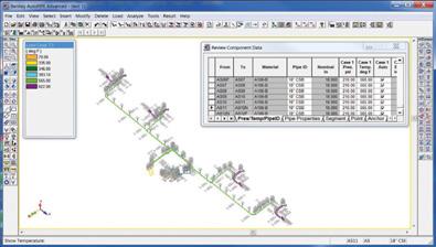
Pipe systems in AutoPIPE ®
Via a DXF export file the support designs, including dimensioning, can be exported optionally with parts lists, site plans, and title block to CAD programs (e.g. AutoCAD® or MicroStation®). This interface is part of the basic LICAD® package. For export, the material list (STL) and design data (TEC) files are additionally generated; they can be used for further evaluations.
On the basis of component libraries the drawings prepared in LICAD® can be transformed into 3D drawings via add-ons in various CAD programs. This is possible for:
AutoCAD®, Autodesk
AutoCAD® Plant 3D, Autodesk MicroStation®, Bentley Systems
SmartPlant ® 3D /Smart™ 3D, Intergraph® PDS ®, Intergraph®
SUPPORT MODELER ®, Intergraph®
For the above mentioned programs the corresponding modules are to be uploaded and installed.
For the PDMS™ software from AVEVA no add-on is registered. A menu extension is available by which data can be conventionally imported and exported.
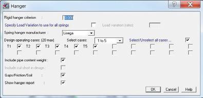
AutoPIPE ® hanger filter
LICAD® plug-ins
LICAD® plug-ins for different systems are also available. These are used in cases where supports are to be designed interactively in a 3D model. The advantage of a plug-in is that the geometric data of the connection points for the support, as well as pipe diameters, height notations and, if required, the design data are exported directly to the program. There is no longer any need to take measurements in the model. The support chain is automatically displayed in the 3D model.
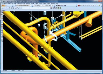


The attributes of the material lists are also imported, depending on the system.
Important: In order for the plug-ins to function, LICAD® must be installed at the respective work station.


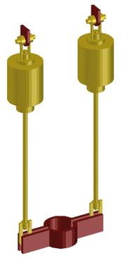
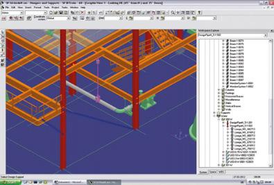
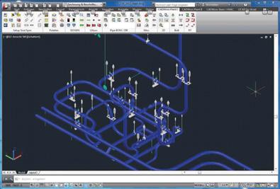
For further designing in the 2D and 3D modes, comprehensive LISEGA component libraries are available, amongst other things, for the following CAD programs:
AutoCAD®, Autodesk
AutoCAD® Plant 3D, Autodesk MicroStation®, Bentley Systems
SmartPlant ® 3D / Smart™ 3D , Intergraph® PDS ®, Intergraph® PDMS™, AVEVA™ SUPPORT MODELER ®, Intergraph® TEKLA Structures, TEKLA®
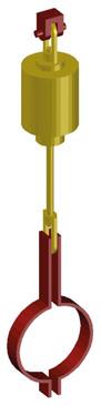
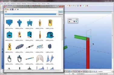
Through LICAD®, the most suitable standard support configurations for each case are determined and from this the corresponding load chains, including all individual parts, are specified.
In plant construction, standard supports are the connecting links between pipe systems and steelwork. In ideal cases they can be directly connected to the existing plant structure, but often a further step is necessary, that is, the use of additional steelwork components as connecting elements (secondary steel). It therefore makes sense to be able to display standard supports in steelwork programs. For this, LICAD® provides interfaces to steelwork programs (e.g. TEKLA Structures software). By means of the plug-in function, LICAD® is integrated into the steelwork program and supports can be directly planned in accordance with the requirements of the model.
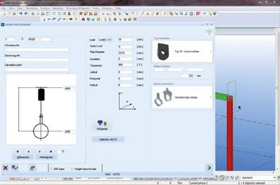
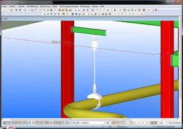
Interactively designed support in TEKLA Structures
This, together with all other plant components in the model, enables the execution of a clash check, which is necessary when planning complex plants.
With the development of the steelwork interface LISEGA supplies a tool that can reduce the enormous investment in time and so optimize the quality of the planning process.
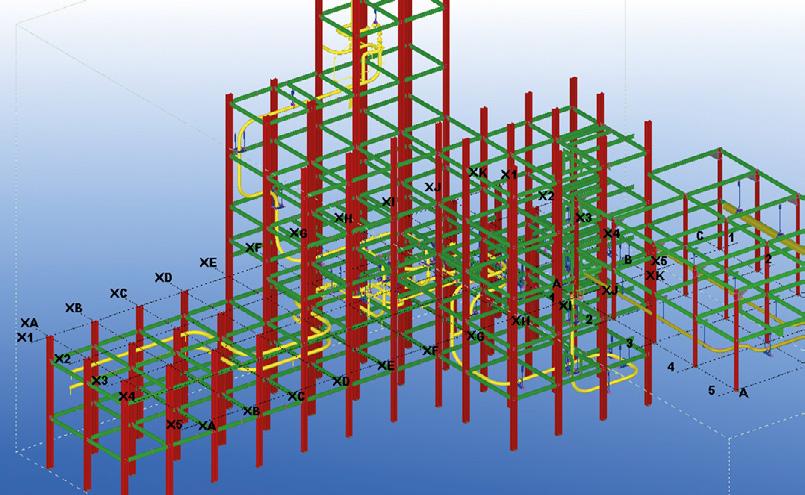
LICAD® and other software packages are being constantly updated and expanded. The applicable program version and interfaces in each case can be found on the LISEGA homepage for downloading.
The use of LICAD ® software is free of charge.

The necessary license numbers are thereby forwarded automatically by e-mail to the recipient. Further license numbers can be obtained by telephone.
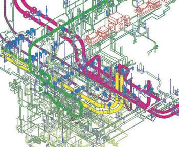


The LISEGA product program presented in this catalog STANDARD SUPPORTS incorporates the latest technical developments with respect to the proper support of pipe systems in industrial plant construction.
The relevant international stipulations are observed to the fullest extent.
The standard design described covers the normal field of application. In special sectors, for example, nuclear or offshore installations, supplementary measures with regard to material quality or corrosion protection may be required. The implementation of particular customer specifications is ensured by the integrated quality management system. Certificates of approval are supplied with the order.
The LISEGA performance package includes not only the product spectrum but a range of services within the framework of product application. In the field of engineering they cover the whole process chain from pipe system design to support planning in all the current 3D design sectors. The service field comprises the usual support when commissioning, right through to plant analyses and walk-downs. Through the use of specially developed software for support design highly effective support is available, e.g. in the 3D CAD sector.
By means of tightly-focused supplementary services the LISEGA standard program can be adapted to particular requirements. In this way the field of application of the products is widened and the LISEGA performance package optimized. All major supplementary services are standardized in line with the LISEGA modular system and cataloged in product group 9.
Constant and spring hangers/supports are adjusted to installation load on a hydraulic test bench via computerized force and travel measurement, then blocked.
9.1.1 Storage of the blocking devices
On request the spring hangers/supports can be equipped for permanent storage of the blocking devices (after deblocking) on the casing. This is standard practice on the constant hangers.
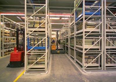
9.2.1 Inspection reports
If required, inspection reports with digitally recorded values can be supplied as function verification for constant hangers, spring hangers and snubbers.
9.2.2 In-service tests
In-service tests can be performed on the mechanically operating components of any make in the respective LISEGA factories or by using mobile test benches directly within the plant itself.
9.2.3 Material certification
The following material certification can be supplied on request.
9.2.4 Supplier’s certificate
Manufacturer and shipment in compliance with the order can be confirmed with a supplier’s certificate according to DIN EN 10204-2.1.
9.2.5 Material certificates
DIN EN 10204-2.2
The materials used in all catalog components can be verified by verification certificates according to DIN EN 10204-2.2.

DIN EN 10204-3.1
Components exposed to the direct flow of force such as, for example, the springs in constant and spring hangers or supports, can be supplied with certificates according to DIN EN 10204-3.1.
9.2.7 Complete traceability through acceptance test certificates
DIN EN 10204-3.1
Due to separate fabrication, complete traceability is possible of materials in all catalog components with test certificates according to DIN EN 10204-3.1.
9.2.8 Pre-examination documents
The standardized products were largely certified by independent inspection bodies by specified suitability and type tests according to KTA 3265.3 and VGB-R 510 L.
Pre-examination documents such as design drawings, parts lists, calculations, test sequence schedules and welding plans can be produced for special designs, particularly non-standardized components (also for other codes).
For applications subject to increased safety and quality demands, such as nuclear installations, the highest level of the quality assurance program is implemented. All stages of order processing and execution are followed according to recognized procedures, in line with the quality stipulations in the standard codes KTA or ASME section III, NCA and NF.
The following areas are thereby taken into special account:
material acquisition from approved suppliers complete traceability of materials strict supervision of manufacture
All areas are fully documented.
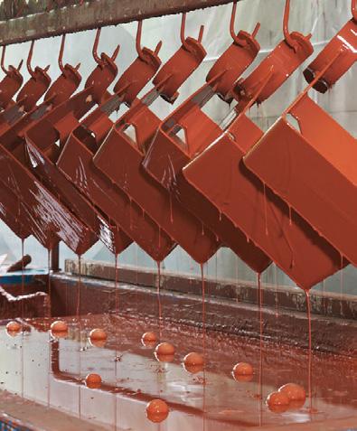
In addition to specified standardized surface protection, further corrosion protection can be supplied according to technical specifications, from page 0.10.
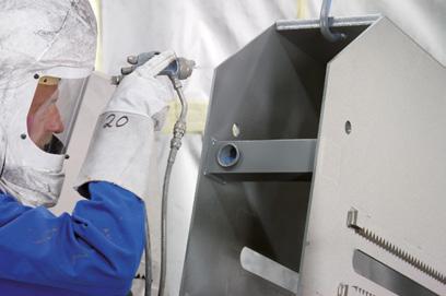
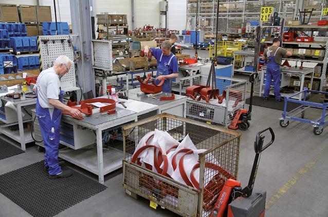
Pre-assembly of load chains Special treatment
Besides the standard designs available from stock, special designs providing extra corrosion protection can be agreed on. For this, separate manufacturing may be required.
If not otherwise agreed, the components belonging to one scope of supply will be packed in bundles according to types.
9.4.1 Pre-assembly of load chains
For simple handling and time-saving assembly at site, the individual components are supplied already pre-assembled into load chains, according support drawings bundled and marked.
Constant and spring hangers/supports, as well as larger pipe clamps (bulky components), are kept separate for easier handling and are correspondingly marked.
9.4.2 Pre-assembly of pipe clamps and clamp bases
Pipe clamp and clamp base halves are bolted ready for shipment and supplied as complete units.
If not otherwise agreed, the components are sorted according to type, packed and marked with quantity, type number and order number. Additional labeling and marking can, if required, be applied.
9.5.1 Marking of individual parts
If required, all components can be marked individually with type, support position number or order number.
9.5.2 Second name plate
If required, spring hangers and constant hangers can be fitted with a second name plate.
9.5.3 Second load and travel scale
If required, constant spring hangers/spring supports can be fitted with a second travel scale and constant hangers/supports with a second load scale.
Appropriate forms of packaging are provided for the various requirements.
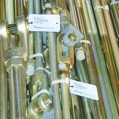
Load chains, pre-assembled, bundled and marked
For road or rail transport, sturdy wooden crates or pallets are offered, fitted with skids for forklifting.
9.6.2
For sea transport, special wooden crates are used, with skids for fork-lifting and with reinforced side walls for any transport by crane. The lids of the crates are lined inside with plastic shrink wrap as protection against moisture.
Other special forms of packaging can be agreed upon in detail.
As a globally operating export company, LISEGA and all its affiliated companies take full responsibility for completely fulfilling all customs and export stipulations.
To ensure and properly execute export control, LISEGA has set up structures that correspond, on the one hand, to legal requirements and, on the other, to a smooth and effective work flow.
By certification as “Authorized Economic Operator” (AEO-F) in the year 2009 and as “Known Consignor” in March 2012, LISEGA has shown that it meets all prerequisites for the support of a secure supply chain.
Together with the simplified customs procedures granted by the AEO certificate for the accelerated export of goods, the independent declaration of preferences, as well as the package acceptance free of any control for airfreight due to our “Known Consignor” status, this contributes noticeably to the trouble-free preferential export processing of LISEGA products.
The personnel in our export office all have comprehensive and regularly updated expert knowledge in all aspects of shipment processing.
Should LISEGA not already be responsible for customs clearance according to the terms of delivery, we will assume this at the customer’s request, also in the form of direct representation, after being granted power of attorney for customs.
Our notable competence in shipping processing is matched by the high standards of packaging and marking at LISEGA, fully covering all international standardized stipulations in the land, sea and air transport sectors. This is confirmed by the unanimously high acceptance shown by our customers.
If requested, we will take charge of the logistics processing for shipment of the components to the construction site or any other shipping addresses.
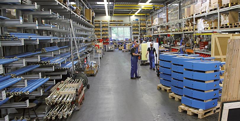

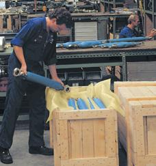
The proper functional integration of pipe supports into the existing piping and plant concept has a decisive influence on the long-term behavior of the pipe systems. Support design should therefore be given the same care and attention as the piping itself. In this regard, selection of the component, the availability of the latest design software and especially the long experience of the planning engineers have a decisive influence on the quality of design.
Besides stringent demands concerning quality it is also important in support planning to fulfill strict requirements regarding tight schedules and economic targets. In order not to endanger the budgets and logistics of entire projects, complete planning phases are outsourced to engineering offices specialized in the work.
As a specialist, LISEGA has long been qualified in the processing of complex planning projects by offering the relevant expertise from over 50 years’ experience in support technology. At all LISEGA locations highly qualified and experienced technicians and engineers are on hand.For internationally overlapping projects and whenever required, the engineering sections of the individual locations work in collaboration with each other.
The following benefits are offered to the customer when using LISEGA’s planning expertise:
economical limitation of their own personnel deployment high security and professional execution through the use of experienced specialists rapid and flexible processing of the whole project, from ordering to shipping, following the principle ‘All from a single source’
quick delivery due to prompt processing complete and permanent computerized documentation highly qualified experts always on hand for follow-up service
Pipe supports for complete plants, including secondary steelwork are conceived, planned and reproduced in drawings. On the basis of the LISEGA modular system and decades of experience, ready-to-install load chains – from structural attachments to pipe-surrounding components – are generated from standard supports.
Should components be required that do not form part of the standard LISEGA program (e.g. anchors etc.) LISEGA can provide appropriate solutions.
Recognized international technical codes and standards, as well as customer specifications, are thereby taken into account.
The relevant pipe stress analysis data are observed for the design and dimensioning of supports, as well as the detailed pipe system layout plans and structural situation.
Besides LISEGA’s LICAD® program, the latest software is applied for the efficient conversion of the support situations into 2D or 3D models and for the economical generation of drawings. The following standard programs are currently being used:
LICAD® AutoCAD® MicroStation® PDMS™
STAAD.Pro® (static/dynamic calculations for secondary steelwork)
SmartPlant ® review Navisworks®
ROHR2 ® CAESAR II ®
Shown below is an example of a planning sequence for a suitable LISEGA support design in seven steps. Depending on needs and specifications the engineering services can also be offered individually.
The following typical load cases are generally calculated per support point for new and existing plants:
1. Primary loads – weight and internal pressure
2. Secondary loads (thermal expansion) – operating loads – design conditions – boiler out of service – (AB operation of pumps)
3. Occasional loads – earthquakes – wind – pressure impact loads
4. Test loads – water pressure tests – pickling (acid clean)
On the basis of the stipulations and information, ready-to-install load chains from standard attachments to pipe-surrounding components are generated with the LISEGA design program LICAD®
For the calculations the codes ASME B31.1, ASME B31.3 and DIN EN 13480 are usually followed. When ordering, the desired code issue according to version and year must be stated.
In existing plants it is frequently necessary, for reasons of operational safety, to update pipe systems and their supports to meet the requirements of the latest technology. Very often, sufficient calculation documentation on the original layout design is no longer available. If required, the stress analysis can also be supplied for these pipe systems.
In accordance with calculations and customer stipulations, the installed load chain is generated from standard supports with the LICAD design program, from structural attachments right through to pipe-surrounding components.


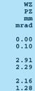
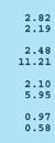


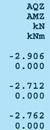
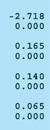
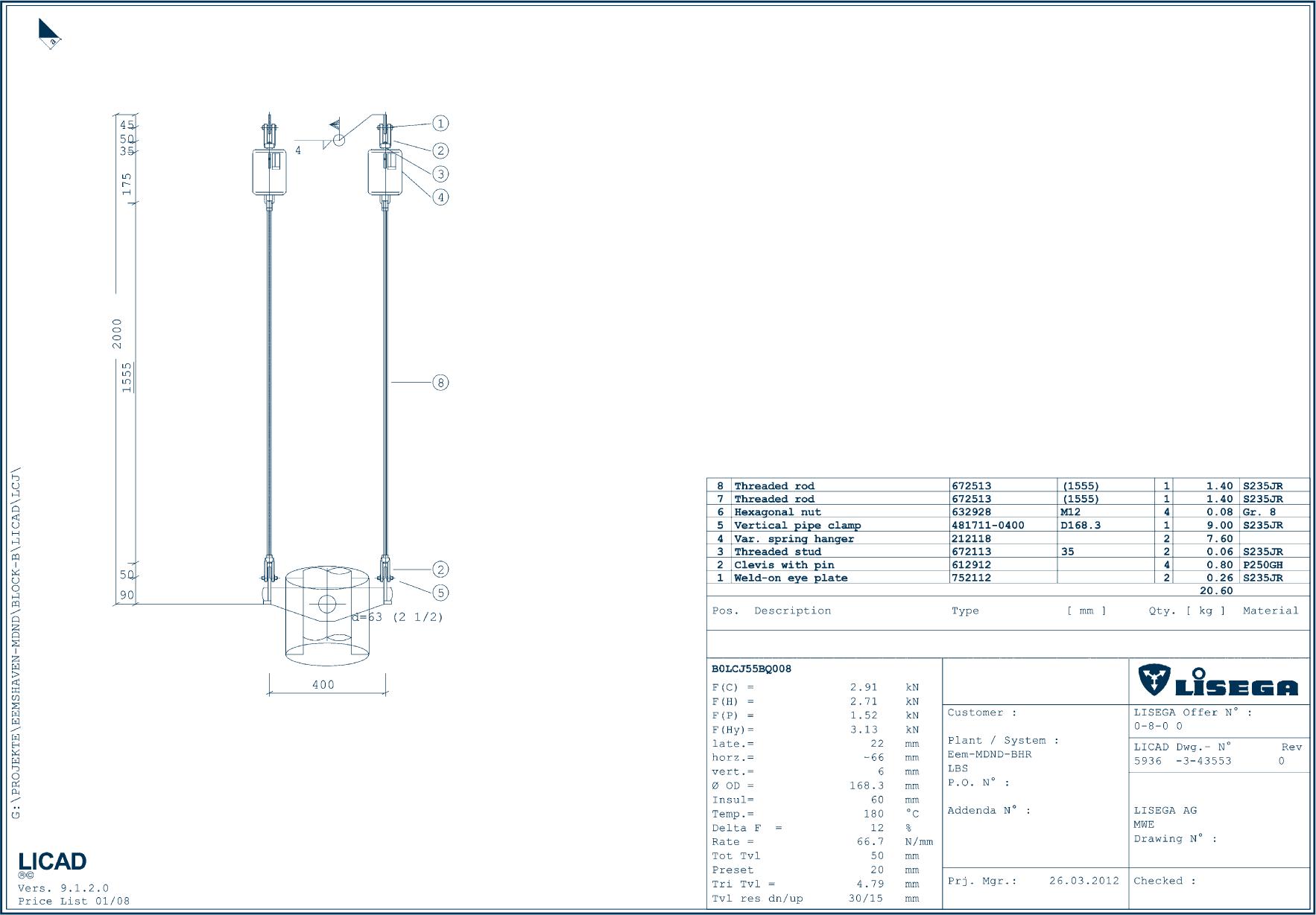
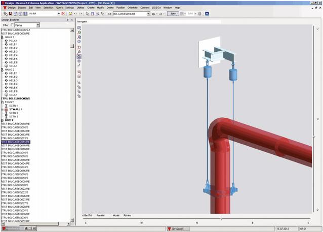
For the design of pipe supports in 3D the customer provides a model complete with pipe systems, steelwork, building structures and components, as well as all the necessary databases. In addition, any specific requirements are to be indicated for the design of the pipe supports.
The support designs are planned directly in 3D (PDMS / SmartPlant), including the secondary steelwork required, and laid out. The load chains generated in LICAD® are imported via existing interfaces into the 3D model. Any secondary steelwork needed can be supplemented directly in PDMS.
Finally, a check is made for any possible interference. The customer receives a database of the 3D model that contains all the support designs checked for freedom from interference.
In almost all other 3D programs LISEGA can, by way of the viewer, edit the characteristics necessary for support design.
For the creation of 3D models on MicroStation® the pipe supports are first generated as 2D displays from a sketch. The 2D data are transformed by LICAD® into 3D data and exported via an interface into the MicroStation® 3D model. Any secondary steelwork required is supplemented in the 3D model. In PDS® the completed 3D models can be used for collision tests.
A 2D drawing is generated directly from the PDMS™ model in DXF format with different views. Parts list, site plan and all the technical specifications are stored as data sets and can be further edited. If required an isometric display of the support on the drawing is possible.
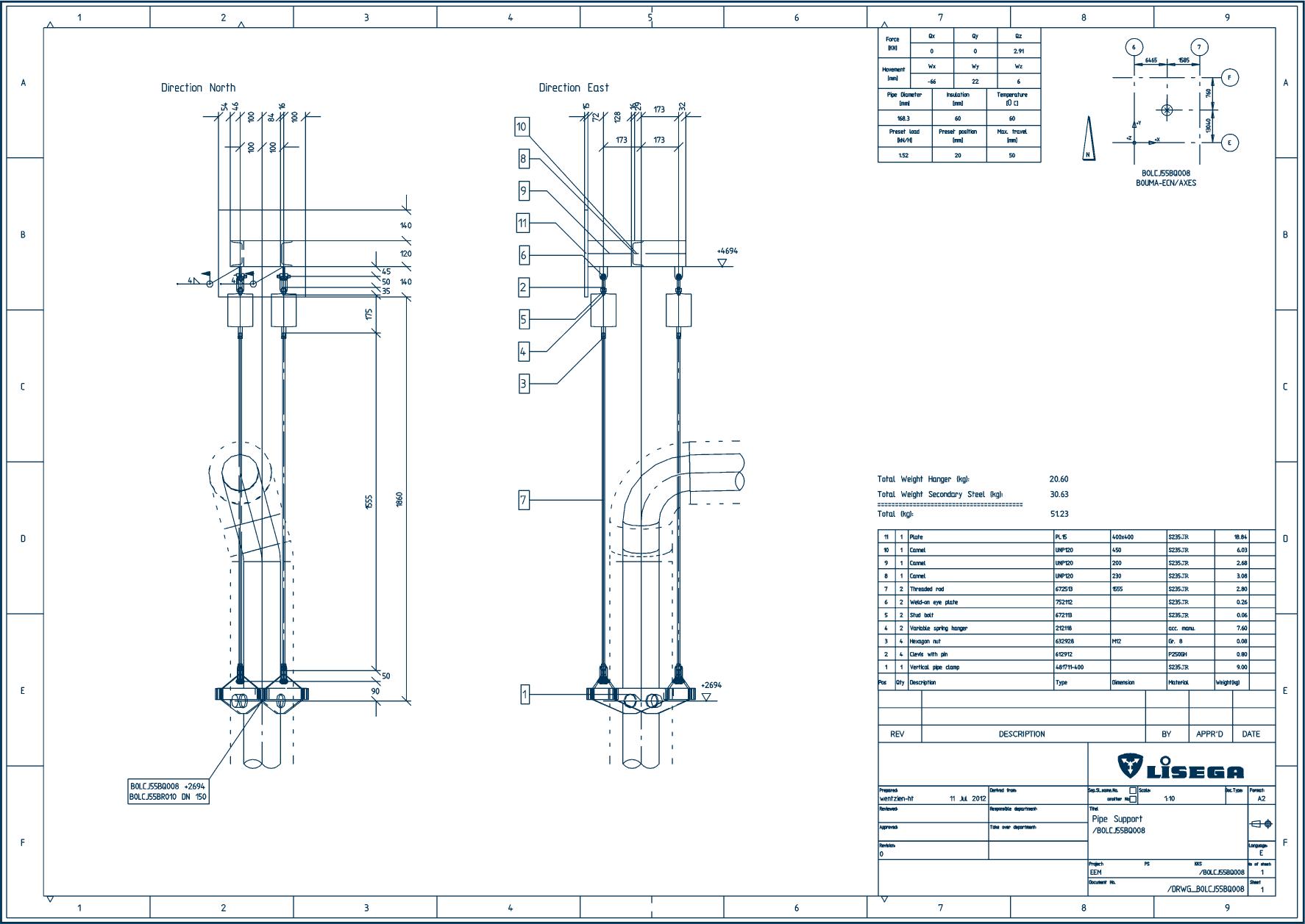
From the drawing generated automatically in Step 5, a production drawing in DWG (AutoCAD®), DXF or DGN (MicroStation®) format is generated. In this, all the information required for installation, including welding specifications, borehole patterns etc. can be seen.
The title block can be individually designed.
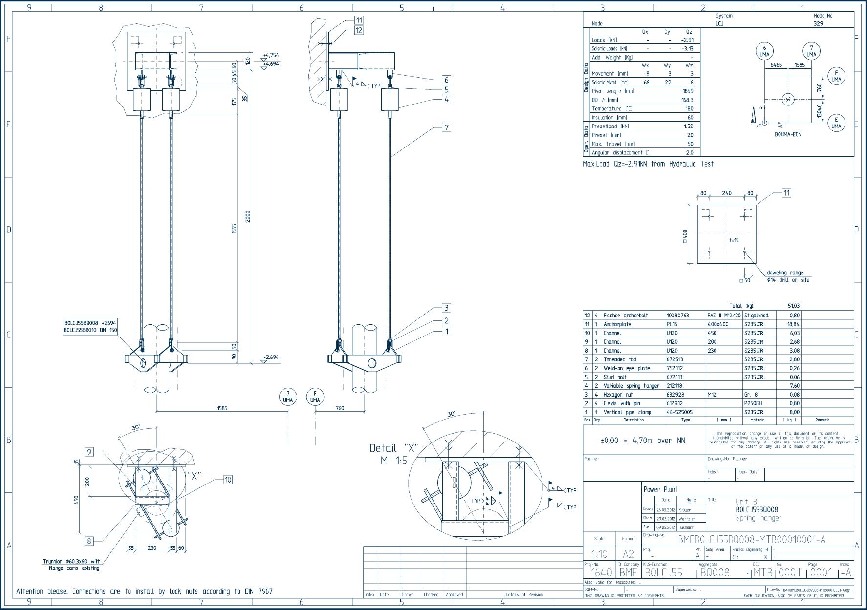
LISEGA supplies the design report summary for the dimensioning of the planned secondary steel according to the AISC code or Eurocode 3. This summary is provided with the STAAD.Pro® statics program.
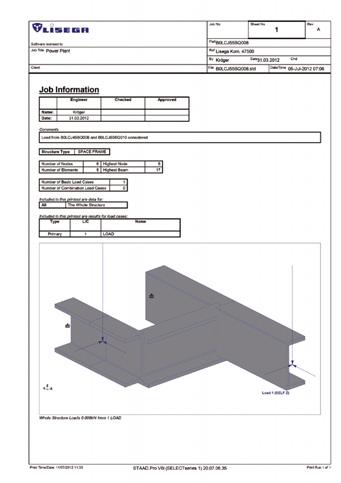
Individual certificates can be provided for most anchor manufacturers with the aid of the corresponding design programs. For economic planning a standard has been developed by which individual certificates can be dispensed with. If required the necessary documentation can be produced.
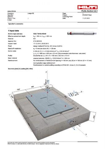
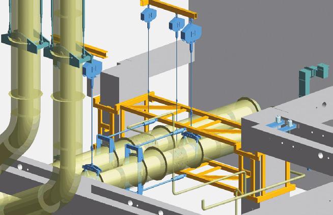
In accordance with the specified codes, individual weld seam certification for steelwork attachments can be provided.
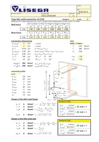
Additional stress and strain due to deficient realized pipe restraints can lead during operation to lasting damage that can considerably increase the risk of malfunction and breakdowns in the plant.
Frequently occurring defects in the pipe supports are:
poor support designs faulty installation incorrect load settings unsuitable layout deficient quality of support components
A particular problem often arises in aged installations when spring and constant hangers with springs that are not pre-relaxed (see page 1.15 on this). In these cases an ever-increasing loss of ultimate load occurs due to growing relaxation over time. The resulting load deviations can lead to impermissible additional stresses, especially at sensitive points such as connections. Timely inspection in the plant can contribute to the prompt identification and elimination of critical stresses.
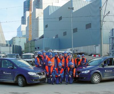
For this special service we offer the resources of an international market leader, with qualified and experienced specialists on hand at all LISEGA Group locations.
Our experts check the thermal pipe displacement and inspect the support systems. They prepare detailed reports on this and propose suitable solutions. For the presentation and documentation of the findings, special software is applied.
The service team is specially trained for the execution of such services in the pipe support field and works strictly in accordance with quality management stipulations and recognized safety guidelines.
The operational safety of pipe systems and hence the readiness and long life of the plants depend in great measure on the condition and functional capacity of the supports used.
To avoid costly damage and breakdowns, regular inspections of the thermal pipe displacement and the condition of the supports – particularly in older plants – is urgently recommended!
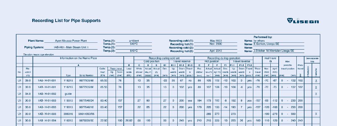
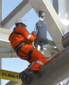
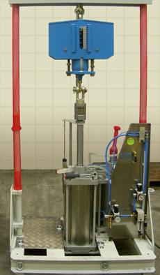
The service package covers the following fields of performance:
inspection of general condition of pipe supports load and travel checking of the spring hangers function testing of constant and spring hangers with mobile test facilities at the plant or on stationary test benches at the LISEGA facility.
inspection of the general condition of the piping sections and if necessary the geometric positioning inspection of the pipe systems for unrestricted freedom of movement in all three planes determination of the vertical displacement at all support points, at the pipe system connections and selected points in all three planes
design and layout of pipe supports for updating and modifications in older plants
measurement work at the plant
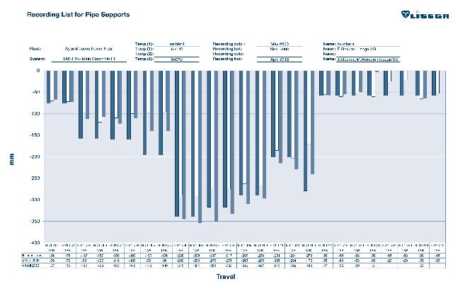
elaboration of solutions to problems arising from restrictions in space design of pipe supports via LICAD® and AutoCAD preparation of lists of parts and materials
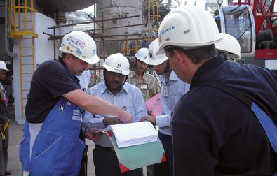
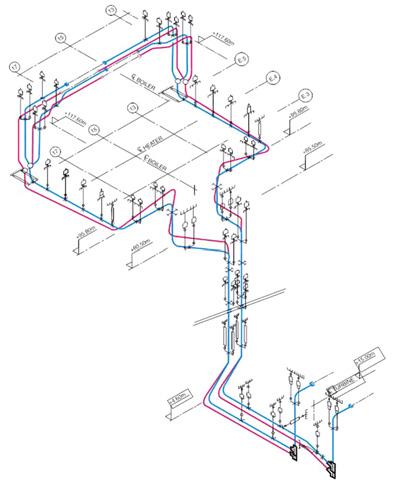
material receipt and control organization and administration of warehouse stocks pre-assembly and arrangement of complete support configurations installation of supports at designated points
supervision of installation of piping into supports prepared inspection of the system for correct installation according to drawings and installation and operating instructions deblocking and commissioning of supports in line with agreed procedures load and travel checks after commissioning according to requirements inspection for freedom of movement in pipe systems in all 3 planes subsequent regulation of hangers if load differences are detected
visual inspection for signs of possible malfunctioning dismounting of snubbers according to stipulations or requirements and documentation of external condition and surrounding conditions function testing on mobile test benches at the plant or on corresponding test facilities at the LISEGA facility dismantling of snubbers and inspection of individual components for wear and damage
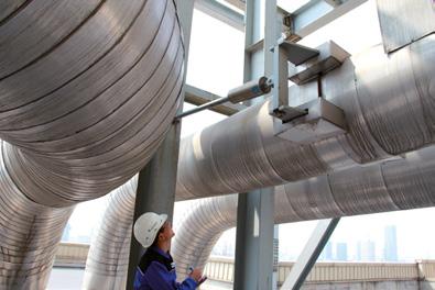
exchange of all seals, hydraulic fluid and any other components showing noticeable wear inal function tests according to test program and specifications on hand re-installation of snubbers at the plant provision of complete final documentation
The wide spectrum of the LISEGA service package applies in particular to pipe supports and their application. If properly implemented, LISEGA service work makes a valuable contribution to the functional safety and long life of complex piping systems.
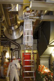
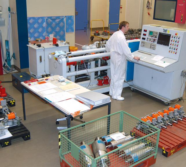
LISEGA SE - Germany
Gerhard-Liesegang-Straße 1
27404 Zeven
Postfach 1357
27393 Zeven
Tel.: +49 (0) 42 81-713-0
Fax: +49 (0) 42 81-713-214
E-Mail: info@de.lisega.com www.lisega.de
LISEGA SAS - France
Z.I. La Marinière 21, Rue Gutenberg 91919 Bondoufle, Cedex
Tel.: +33 (0)1 60 86 40 21
Fax: +33 (0)1 60 86 48 28
E-Mail: info@fr.lisega.com www.lisega.fr
LISEGA Inc. - USA
370 East Dumplin Valley Rd. Kodak, TN 37764
Tel.: +1 (0) 865 940 5200
Fax: +1 (0) 865 940 5140
E-Mail: info@us.lisega.com www.lisega.com
LISEGA Ltd. - England
Unit 3, Washington Centre Halesowen Road Netherton
West Midlands, DY2 9RE
Tel.: +44 (0) 13 84 458 660
Fax: +44 (0) 13 84 213 301
E-Mail: info@uk.lisega.com www.lisega.co.uk
LISEGA PST Co. Ltd. - China
LISEGA Pipe Support Technologies (Shanghai) Co., Ltd.
7800 Songze Av., Qingpu Industrial Zone Shanghai, ZIP 201700, PR China
Tel.: +86 (0) 21 69 21 2888
Fax: +86 (0) 21 69 21 2999
E-Mail: info@cn.lisega.com www.lisega.com.cn