Innovation in Weighing
PRODUCTS CATALOG
D1
JUNCTION BOXES
D2
ACCESSORIES AND WIRINGS
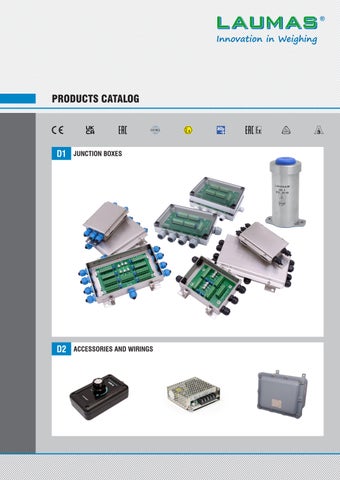
JUNCTION BOXES
ACCESSORIES AND WIRINGS
AISI 304 stainless steel or ABS junction boxes, including equalization boards or parallel connection boards, to connect from 1 to 4 or from 5 to 8 load cells. Hygienic junction boxes. Versions with lightning and electrical shock protection device. Approved versions: ATEX, IECEx, EAC Ex.
The accessories complete the offer of Laumas devices and components for industrial weighing systems: high-efficiency power supplies, load cells signal simulators, cables and PVC sheaths, standard weights.
CERTIFICATIONS
European Conformity Mark (CE)
UKCA CERTIFICATION (UK Conformity Assessed) for the United Kingdom
EAC CERTIFICATION
OIML APPROVAL
ATEX CERTIFICATION
3-A SANITARY STANDARDS
IECEx CERTIFICATION
Testing, calibration, quality control EAC Ex CERTIFICATION
Calibration services accredited by Accredia for load cells and load cells + instrument, performed in our laboratory LAT No. 02141 for force values between 2 and 100 kN, according to UNI EN ISO 376 and ASTM E74 standards. Accredia is the Sole National accreditation body (European Regulation 765/2008) and guarantees compliance with standards and the reliability of conformity certificates issued on the market. The Accredia calibration certificate is an official document recognized worldwide because it is covered by the EA, IAF, and ILAC Mutual Recognition Agreements.
Ex NEPSI CERTIFICATION
In our laboratory, we also perform calibration reports for force values between 0.5 and 5000 kN (compression) and between 0.5 and 600 kN (tension).
Contents PRODUCTS CATALOG
PAGE
LAUMAS S.r.l. Fax: (+39) 0521 681091
• •
D1
JUNCTION BOXES
D1.1
HYGIENIC JUNCTION BOXES
D1.2
INOX JUNCTION BOXES
D1.3
ATEX - INOX JUNCTION BOXES
D1.4
ABS JUNCTION BOXES
D1.5
LOAD CELLS CONNECTION BOARDS
D2
ACCESSORIES AND WIRINGS
D2.1
STABILIZED POWER SUPPLIES
D2.2
LOAD CELL SIMULATOR
D2.3
CABLES - SHEATHES - WIRINGS - SELECTOR SWITCHES
D2.4
STANDARD WEIGHTS
SALES DEPARTMENT: sales@laumas.it Phone: (+39) 0521 683124
4
25
ISO
9001
ISO 14001
www.laumas.com
4
D1 - JUNCTION BOXES PRODUCTS CATALOG
PAGE
LAUMAS S.r.l. Fax: (+39) 0521 681091
• •
D1.1
HYGIENIC JUNCTION BOXES
CDG43A CDG4EQ3A
Hygienic junction boxes in stainless steel with equalization board or parallel connection board
D1.2
INOX JUNCTION BOXES
CE41INOX CE81INOX CE41INOXP C41INOXP
Stainless steel junction boxes with equalization board or parallel connection board
D1.3
ATEX - INOX JUNCTION BOXES
CE41ATEX CE81ATEX CE41PATEX
Stainless steel junction boxes with equalization board
D1.4
ABS JUNCTION BOXES
CE41N/NR CE81PN/PNR CIP67N C41N/NR
ABS junction boxes with equalization board or parallel connection board
D1.5
LOAD CELLS CONNECTION BOARDS
HL6EQSN HL6N
Equalization board Parallel connection board
SALES DEPARTMENT: sales@laumas.it Phone: (+39) 0521 683124
6
8
12
17
22
ISO
9001
ISO 14001
www.laumas.com
5
Notes PRODUCTS CATALOG
LAUMAS S.r.l. Fax: (+39) 0521 681091
• •
SALES DEPARTMENT: sales@laumas.it Phone: (+39) 0521 683124
ISO
9001
ISO 14001
www.laumas.com
6
CDG 3A HYGIENIC JUNCTION BOXES
DESCRIPTION
CODE
Equalization board
CDG4EQ3A
Parallel connection board
CDG43A
Hygienic junction box in AISI 304 stainless steel. Cylindrical design to facilitate sanitization. IP68 protection rating. Blue hygienic cable gland for passage up to 7 cables. Hygienic device RPSCQC authorized by 3-A SSI. Working temperature: -20 °C +60 °C. Up to 4 load cells connection (4/6 wires). Two hygienic M5 screws with seal (included in the supply). CERTIFICATIONS Equivalent of the CE marking for the United Kingdom American standard that regulates the design, production and use of hygienic equipment
R e v. 0 . 0
DIMENSIONS (mm)
LAUMAS S.r.l. Fax: (+39) 0521 681091
• •
SALES DEPARTMENT: sales@laumas.it Phone: (+39) 0521 683124
ISO
9001
ISO 14001
www.laumas.com
7
CDG 3A HYGIENIC JUNCTION BOXES ELECTRICAL CONNECTIONS CDG4EQ3A CE41INOXP
CDG43A C41INOXP
GND -S +S -R -E +R +E
CL3
CL2
CL1 GND -S +S -R -E +R +E
GND -S +S -R -E +R +E
GND -S +S -R -E +R +E
W1
W2
W3
W4
6-WIRES LOAD CELLS CONNECTION COLLEGAMENTO CELLE A 6 FILI
EX -
EX + S+
4-WIRES OUTPUTACABLE CAVO D'USCITA 4 FILI CON4CELLA 4 FILI CELL WITH WIRESA LOAD SHIELD - SIGNAL + SIGNAL
GND -S +S -R -E +R +E
- EXCITATION + EXCITATION
GND -S +S -R -E +R +E
GND -S +S -R -E +R +E
CL2
CL3 GND -S +S -R -E +R +E
GND -S +S -R -E +R +E
CL4 GND -S +S -R -E +R +E
4-WIRES LOAD CELLS CONNECTION COLLEGAMENTO CELLE A 4 FILI
S-
GND -S +S -R -E +R +E
CL1
CL4
GND -S +S -R -E +R +E
GND -S +S -R -E +R +E
6-WIRES OUTPUT ACABLE CAVO D'USCITA 6 FILI CON6 CELLA 6 FILI CELL WITH WIRESALOAD GND -S +S -R -E +R +E
SHIELD - SIGNAL + SIGNAL - Ref./Sense - EXCITATION + Ref./Sense + EXCITATION
SEX -
EX + S+
6-WIRES OUTPUT A CABLE CAVO D'USCITA 6 FILI CON 4 FILI CELL WITH 4 CELLA WIRESALOAD GND -S +S -R -E +R +E
SHIELD - SIGNAL + SIGNAL - Ref./Sense - EXCITATION + Ref./Sense + EXCITATION
EQUALIZATION PROCEDURE (CDG4EQ3A)
R e v. 0 . 0
WARNING! For load cells with 2 mV/V sensitivity the difference between the sensitivities must not be greater than 0.1 mV. For load cells with 3 mV/V sensitivity the difference between the sensitivities must not be greater than 0.15 mV. CDG4EQ3A: the board is equipped with a 20 Ω potentiometer for each load cell. Example with 4 load cells and a sample weight of 978 kg: 1. Turn the potentiometers’screw counterclockwise until to 0 Ω. 2. Place the sample weight in correspondence with the CL1 load cell and take note of the value shown on the display; repeat the same operation for all load cells. Example: CL1 = 1008 kg CL2 = 998 kg CL3 = 973 kg CL4 = 985 kg 3. Adjust the potentiometers related to the higher weight values (W1, W2, W4), leaving the lowest one unchanged (W3). 4. Place the sample weight in correspondence with the CL1 load cell; by adjusting the potentiometer W1 change the value shown on the display from 1008 kg to 973 kg. 5. Place the sample weight in correspondence with the CL2 load cell; by adjusting the potentiometer W2 change the value shown on the display from 998 kg to 973 kg. 6. Place the sample weight in correspondence with the CL4 load cell; by adjusting the potentiometer W3 change the value shown on the display from 985 kg to 973 kg. 7. Place the sample weight in correspondence with the CL3 load cell and take note of the value shown on the display, for example 966 kg. 8. Place the sample weight in correspondence with the CL1 and adjust the potentiometer W1 until 966 kg is displayed. 9. Place the sample weight in correspondence with the CL2 and adjust the potentiometer W2 until 966 kg is displayed. 10. Place the sample weight in correspondence with the CL4 and adjust the potentiometer W4 until 966 kg is displayed. 11. Place the sample weight in correspondence with the CL3 and take note of the value shown on the display, for example 962 kg. 12. Repeat the procedure several times until the display shows the same weight value for all four load cells. 13. Remove the sample weight and zero the tare, then place the sample weight in the middle and calibrate the instrument (see the instrument’s user manual).
LAUMAS S.r.l. Fax: (+39) 0521 681091
• •
SALES DEPARTMENT: sales@laumas.it Phone: (+39) 0521 683124
ISO
9001
ISO 14001
www.laumas.com
8
JUNCTION BOXES AISI 304 STAINLESS STEEL
AISI 304 STAINLESS STEEL JUNCTION BOX IP67 PROTECTION RATING WORKING TEMPERATURE: -20 °C +60 °C 4/6 WIRES LOAD CELLS CONNECTION EARTH TERMINAL DESCRIPTION
CODE
EQUALIZATION BOARD
Up to 4 load cells connection. 4+1 polyamid cable glands M16x1.5 - plugs. Lightning and electrical shock protection device.
CE41INOX
Up to 8 load cells connection. 8+1 polyamid cable glands M16x1.5 - plugs. Lightning and electrical shock protection device.
CE81INOX
Up to 4 load cells connection. 4+1 polyamid cable glands M12x1.5 - plugs.
CE41INOXP
PARALLEL CONNECTION BOARD
Up to 4 load cells connection. 4+1 polyamid cable glands M12x1.5 - plugs.
C41INOXP
CERTIFICATIONS
R e v. 0. 0
Complies with the Eurasian Customs Union regulations Equivalent of the CE marking for the United Kingdom
LAUMAS S.r.l. Fax: (+39) 0521 681091
• •
SALES DEPARTMENT: sales@laumas.it Phone: (+39) 0521 683124
ISO
9001
ISO 14001
www.laumas.com
9
JUNCTION BOXES AISI 304 STAINLESS STEEL DIMENSIONS (mm)
CE41INOX
CE81INOX
CE41INOX - CE41ATEX
4x Ø8
43
42
CE81INOX - CE81ATEX
147
4x Ø8
112
135
142
128 144
149
8+1 M16x1.5
4+1 M16x1.5
200 CE41INOXP - C41INOXP
42
CE41INOXP - C41INOXP - CE41PATEX
90
6.5
20
4+1 M12x1.5
160
R e v. 0. 0
176
LAUMAS S.r.l. Fax: (+39) 0521 681091
• •
SALES DEPARTMENT: sales@laumas.it Phone: (+39) 0521 683124
ISO
9001
ISO 14001
www.laumas.com
10
JUNCTION BOXES AISI 304 STAINLESS STEEL ELECTRICAL CONNECTIONS
CE41INOX CE41INOX
D4
D5
D6
W3
CL3
D6
-E -R -S
+S+R+E
GND
+E +R +S GND -S -R -E
D5
+E +R +S GND -S -R -E
D4
W4
W4
W5
W6
W7
W8
-E -R -S GND +S +R +E
D3
6-WIRES LOAD CELLS COLLEGAMENTO CONNECTION CELLE A 6 FILI
EX -
EX -
SEX +
S-
S+
S+
S-
-E -R -S GND +S +R +E
D2
W2
W3
6-WIRES LOAD CELLSCELLE CONNECTION COLLEGAMENTO A 6 FILI
EX -
D1
-E -R -S GND +S +R +E
+E +R +S GND -S -R -E
W1
CL1
D3
-E -R -S GND +S +R +E
-E -R -S GND +S +R +E
W1
-E -R -S GND +S +R +E
D2
-E -R -S GND +S +R +E
-E -R -S GND +S +R +E
+E +R +S GND -S -R -E
D1
CL4
-E -R -S GND +S +R +E
W2
CL2
-E -R -S GND +S +R +E
CE81INOX CE81INOX
S+ EX +
EX +
4-WIRES LOAD CELLS COLLEGAMENTO CONNECTION CELLE A 4 FILI
-E -R -S GND +S +R +E
+E +R +S GND -S -R -E
4-WIRES LOAD CELLSCELLE CONNECTION COLLEGAMENTO A 4 FILI SEX -
-E -R -S GND +S +R +E
EX +
S+ EX -
EX -
- SIGNAL SHIELD + SIGNAL
6-WIRES OUTPUT CABLE CAVO D'USCITA A 6 FILI WITHCON 6 WIRES CELL CELLALOAD A 6 FILI
6-WIRES CABLE CAVOOUTPUT D'USCITA A 6 FILI WITH 4 WIRES CELL CON CELLALOAD A 4 FILI
-E -R -S GND +S +R +E
-E -R -S GND +S +R +E
- EXCITATION - Ref./Sense - SIGNAL SHIELD + SIGNAL + Ref./Sense + EXCITATION
- EXCITATION - Ref./Sense - SIGNAL SHIELD + SIGNAL + Ref./Sense + EXCITATION
R e v. 0. 0
+ EXCITATION
EX +
EX +
- EXCITATION
-E -R -S GND +S +R +E
S-
S+
S+
S-
4-WIRES OUTPUT CABLE CAVO D'USCITA A 4 FILI WITHCON 4 WIRES LOAD CELL CELLA A 4 FILI
LAUMAS S.r.l. Fax: (+39) 0521 681091
• •
SALES DEPARTMENT: sales@laumas.it Phone: (+39) 0521 683124
ISO
9001
ISO 14001
www.laumas.com
11
JUNCTION BOXES AISI 304 STAINLESS STEEL ELECTRICAL CONNECTIONS CE41INOXP CE41INOXP
C41INOXP C41INOXP CL1
GND -S +S -R -E +R +E
CL3
CL2
CL4
GND -S +S -R -E +R +E
GND -S +S -R -E +R +E
GND -S +S -R -E +R +E
GND -S +S -R -E +R +E
W1
W2
W3
W4
6-WIRES LOAD CELLS CONNECTION COLLEGAMENTO CELLE A 6 FILI
EX -
EX + S+
4-WIRES OUTPUT A CABLE CAVO D'USCITA 4 FILI WITH 4 WIRES CON CELLA ALOAD 4 FILI CELL SHIELD - SIGNAL + SIGNAL
GND -S +S -R -E +R +E
- EXCITATION + EXCITATION
GND -S +S -R -E +R +E
CL2
CL3
GND -S +S -R -E +R +E
GND -S +S -R -E +R +E
CL4 GND -S +S -R -E +R +E
4-WIRES LOAD CELLS CONNECTION COLLEGAMENTO CELLE A 4 FILI
S-
GND -S +S -R -E +R +E
CL1 GND -S +S -R -E +R +E
GND -S +S -R -E +R +E
6-WIRES OUTPUT A CABLE CAVO D'USCITA 6 FILI WITH 6 CELLA WIRESALOAD CON 6 FILI CELL GND -S +S -R -E +R +E
SHIELD - SIGNAL + SIGNAL - Ref./Sense - EXCITATION + Ref./Sense + EXCITATION
SEX -
EX + S+
6-WIRES OUTPUT A CABLE CAVO D'USCITA 6 FILI WITH 4 WIRES CON CELLA ALOAD 4 FILI CELL GND -S +S -R -E +R +E
SHIELD - SIGNAL + SIGNAL - Ref./Sense - EXCITATION + Ref./Sense + EXCITATION
EQUALIZATION PROCEDURE WARNING!
For load cells with 2 mV/V sensitivity the difference between the sensitivities must not be greater than 0.1 mV.
R e v. 0. 0
For load cells with 3 mV/V sensitivity the difference between the sensitivities must not be greater than 0.15 mV. The board is equipped with a 20 Ω potentiometer for each load cell.
Example with 4 load cells and a sample weight of 978 kg: 1. Turn the potentiometers’screw counterclockwise until to 0 Ω. 2. Place the sample weight in correspondence with the CL1 load cell and take note of the value shown on the display; repeat the same operation for all load cells. Example: CL1 = 1008 kg CL2 = 998 kg CL3 = 973 kg CL4 = 985 kg 3. Adjust the potentiometers related to the higher weight values (W1, W2, W4), leaving the lowest one unchanged (W3). 4. Place the sample weight in correspondence with the CL1 load cell; by adjusting the potentiometer W1 change the value shown on the display from 1008 kg to 973 kg. 5. Place the sample weight in correspondence with the CL2 load cell; by adjusting the potentiometer W2 change the value shown on the display from 998 kg to 973 kg. 6. Place the sample weight in correspondence with the CL4 load cell; by adjusting the potentiometer W3 change the value shown on the display from 985 kg to 973 kg. 7. Place the sample weight in correspondence with the CL3 load cell and take note of the value shown on the display, for example 966 kg. 8. Place the sample weight in correspondence with the CL1 and adjust the potentiometer W1 until 966 kg is displayed. 9. Place the sample weight in correspondence with the CL2 and adjust the potentiometer W2 until 966 kg is displayed. 10. Place the sample weight in correspondence with the CL4 and adjust the potentiometer W3 until 966 kg is displayed. 11. Place the sample weight in correspondence with the CL3 and take note of the value shown on the display, for example 962 kg. 12. Repeat the procedure several times until the display shows the same weight value for all four load cells. 13. Remove the sample weight and zero the tare, then place the sample weight in the middle and calibrate the instrument (see the instrument’s user manual). Th e Com p any re se r ve s t h e r i g h t to m ake c h a n ge s to t h e te c h n i ca l d a t a , d ra w i n gs a n d i m a ge s w i t h o u t n o t i ce.
LAUMAS S.r.l. Fax: (+39) 0521 681091
• •
SALES DEPARTMENT: sales@laumas.it Phone: (+39) 0521 683124
ISO
9001
ISO 14001
www.laumas.com
12
ATEX/IECEx JUNCTION BOXES AISI 304 STAINLESS STEEL II 1G Ex ia IIC T4 II 1D Ex ta IIIC T85°C
-20 °C ≤ Tamb +60 °C -20 °C ≤ Tamb +60 °C
AISI 304 STAINLESS STEEL JUNCTION BOX IP67 PROTECTION RATING 4/6 WIRES LOAD CELLS CONNECTION EARTH TERMINAL
DESCRIPTION
CODE
EQUALIZATION BOARD
Up to 4 load cells connection. 4+1 polyamid cable glands M16x1.5 - plugs.
CE41ATEX
Up to 8 load cells connection. 8+1 polyamid cable glands M16x1.5 - plugs.
CE81ATEX
Up to 4 load cells connection. 4+1 polyamid cable glands M12x1.5 - plugs.
CE41PATEX
CERTIFICATIONS ATEX/IECEx (zone 1-21) Complies with the Eurasian Customs Union standards Equivalent of the CE marking for the United Kingdom CERTIFICATIONS ON REQUEST
R e v. 0. 0
Complies with the Eurasian Customs Union standards for use in potentially explosive atmospheres Complies with Chinese market regulations for use in potentially explosive atmospheres
LAUMAS S.r.l. Fax: (+39) 0521 681091
• •
SALES DEPARTMENT: sales@laumas.it Phone: (+39) 0521 683124
ISO
9001
ISO 14001
www.laumas.com
13
ATEX/IECEx JUNCTION BOXES AISI 304 STAINLESS STEEL INSTALLATION AND MAINTENANCE
Connect the junction boxes to the earthing system. Use appropriate section cables in accordance with the technical standard EN60079-14:2014. For junction boxes installed in dangerous areas use ATEX Ex ia certified barriers placed in a safe area. Periodically wipe the junction boxes surface with a damp cloth to prevent dust buildup. Replace the cable gland membrane if it is damaged to prevent gas or dust entering the junction box.
DIMENSIONS (mm)
CE81ATEX CE81INOX - CE81ATEX
4x Ø8
43
42
CE41INOX - CE41ATEX CE41ATEX
147
4x Ø8
112
135
142
128 144
149
8+1 M16x1.5
4+1 M16x1.5
200
42
CE41PATEX CE41INOXP - C41INOXP - CE41PATEX
90
6.5
20
4+1 M12x1.5
160
R e v. 0. 0
176
LAUMAS S.r.l. Fax: (+39) 0521 681091
• •
SALES DEPARTMENT: sales@laumas.it Phone: (+39) 0521 683124
ISO
9001
ISO 14001
www.laumas.com
14
ATEX/IECEx JUNCTION BOXES AISI 304 STAINLESS STEEL ELECTRICAL CONNECTIONS
CAVO D'USCITA CE41ATEX - CE81ATEX OUTPUT CABLE: CE41ATEX - CE81ATEX
SHIELD
7766Pac
2
7761ac
4
AREA PERICOLOSA DANGEROUS AREA
2 1
4 3
+ SIGNAL + Ref./Sense + EXCITATION
- Ref./Sense - EXCITATION + EXCITATION + Ref./Sense + SIGNAL - SIGNAL
1
3
- EXCITATION - Ref./Sense - SIGNAL
-E -R -S GND +S +R +E
Collegare allato rete di terra Connect the dell'impianto a sicurezza intrinsically safe intrinseca
AREA SAFE SICURA AREA
system earth terminal
CE41ATEX CE41INOX - CE41ATEX
CE81ATEX CE81INOX - CE81ATEX
D3
D4
D5
D6
W3
CL3
D6
W4
-E -R -S
+S+ R+E
GND
+E +R +S GND -S -R -E
D5
W4
W3
W5
W6
W7
W8
-E -R -S GND +S +R +E
D2
-E -R -S GND +S +R +E
D1
W2
+E +R +S GND -S -R -E
D4
-E -R -S GND +S +R +E
+E +R +S GND -S -R -E
W1
CL1
D3
CL4
-E -R -S GND +S +R +E
-E -R -S GND +S +R +E
W1
-E -R -S GND +S +R +E
D2
-E -R -S GND +S +R +E
-E -R -S GND +S +R +E
+E +R +S GND -S -R -E
D1
W2
CL2
-E -R -S GND +S +R +E
6-WIRE LOAD CELLS COLLEGAMENTO CONNECTION CELLE A 6 FILI
COLLEGAMENTO A 6 FILI 6-WIRE LOAD CELLSCELLE CONNECTION
EX + S-
S+
S+
S-
-E -R -S GND +S +R +E
EX -
EX -
SEX -
S+ EX +
EX +
4-WIRE
-E -R -S GND +S +R +E
+E +R +S GND -S -R -E
4-WIRE LOAD CELLSCELLE CONNECTION COLLEGAMENTO A 4 FILI
COLLEGAMENTO LOAD CELLS CELLE A 4 FILI CONNECTION
SEX -
-E -R -S GND +S +R +E
EX +
S+ EX -
EX -
R e v. 0. 0
- EXCITATION
-E -R -S GND +S +R +E
LAUMAS S.r.l. Fax: (+39) 0521 681091
- SIGNAL SHIELD + SIGNAL + EXCITATION
• •
EX +
EX +
CON CELLA A 4 FILI
6-WIRE OUTPUT CABLE D'USCITA 6 FILI WITHCAVO 6-WIRE LOAD ACELL
6-WIRE OUTPUT CABLE D'USCITA 6 FILI WITHCAVO 4-WIRE LOAD ACELL
-E -R -S GND +S +R +E
-E -R -S GND +S +R +E
CON CELLA A 6 FILI
SALES DEPARTMENT: sales@laumas.it Phone: (+39) 0521 683124
- EXCITATION - Ref./Sense - SIGNAL SHIELD + SIGNAL + Ref./Sense + EXCITATION
S-
S+
S+
S-
4-WIRE OUTPUT CABLE D'USCITA 4 FILI WITHCAVO 4-WIRE LOAD ACELL
CON CELLA A 4 FILI
- EXCITATION - Ref./Sense - SIGNAL SHIELD + SIGNAL + Ref./Sense + EXCITATION
ISO
9001
ISO 14001
www.laumas.com
15
ATEX/IECEx JUNCTION BOXES AISI 304 STAINLESS STEEL ELECTRICAL CONNECTIONS
OUTPUT CABLE: CEP41ATEX CAVO D'USCITA CE41PATEX
AREA PERICOLOSA DANGEROUS AREA
2
4
7761ac
2 1
4 3
7766Pac
- Ref./Sense - EXCITATION + EXCITATION + Ref./Sense + SIGNAL - SIGNAL
1
- SIGNAL + SIGNAL - Ref./Sense - EXCITATION + Ref./Sense + EXCITATION
3
GND -S +S -R -E +R +E
SHIELD
Collegare allatorete di terra Connect the dell'impianto a sicurezza intrinsically safe intrinseca system earth terminal
AREA SAFE SICURA AREA
CE41PATEX CE41PATEX CL1 GND -S +S -R -E +R +E
CL2 GND -S +S -R -E +R +E
GND -S +S -R -E +R +E
GND -S +S -R -E +R +E
W1
W2
W3
W4
6-WIRECOLLEGAMENTO LOAD CELLS CONNECTION CELLE A 6 FILI
COLLEGAMENTO CELLECONNECTION A 4 FILI 4-WIRE LOAD CELLS
S-
GND -S +S -R -E +R +E
EX -
EX + S+
4-WIRECAVO OUTPUT CABLE D'USCITA A 4 FILI WITH 4CON WIRES LOAD CELLA A 4CELL FILI SHIELD - SIGNAL + SIGNAL
GND -S +S -R -E +R +E
- EXCITATION
GND -S +S -R -E +R +E
SEX -
EX + S+
6-WIRE OUTPUT CABLE CAVO D'USCITA A 6 FILI WITH WIRES CON 6 CELLA A 6LOAD FILI CELL GND -S +S -R -E +R +E
SHIELD - SIGNAL + SIGNAL - Ref./Sense - EXCITATION + Ref./Sense + EXCITATION
6-WIRE OUTPUT CABLE
CAVO D'USCITA A 6 FILI WITH 4 WIRES LOAD CELL CON CELLA A 4 FILI GND -S +S -R -E +R +E
SHIELD - SIGNAL + SIGNAL - Ref./Sense - EXCITATION + Ref./Sense + EXCITATION
R e v. 0. 0
+ EXCITATION
CL4
CL3
GND -S +S -R -E +R +E
LAUMAS S.r.l. Fax: (+39) 0521 681091
• •
SALES DEPARTMENT: sales@laumas.it Phone: (+39) 0521 683124
ISO
9001
ISO 14001
www.laumas.com
16
ATEX/IECEx JUNCTION BOXES AISI 304 STAINLESS STEEL EQUALIZATION PROCEDURE
WARNING!
For load cells with 2 mV/V sensitivity the difference between the sensitivities must not be greater than 0.1 mV. For load cells with 3 mV/V sensitivity the difference between the sensitivities must not be greater than 0.15 mV.
The board is equipped with a 20 Ω potentiometer for each load cell.
Re v. 0 . 0
Example with 4 load cells and a sample weight of 978 kg: 1. Turn the potentiometers’screw counterclockwise until to 0 Ω. 2. Place the sample weight in correspondence with the CL1 load cell and take note of the value shown on the display; repeat the same operation for all load cells. Example: CL1 = 1008 kg CL2 = 998 kg CL3 = 973 kg CL4 = 985 kg 3. Adjust the potentiometers related to the higher weight values (W1, W2, W4), leaving the lowest one unchanged (W3). 4. Place the sample weight in correspondence with the CL1 load cell; by adjusting the potentiometer W1 change the value shown on the display from 1008 kg to 973 kg. 5. Place the sample weight in correspondence with the CL2 load cell; by adjusting the potentiometer W2 change the value shown on the display from 998 kg to 973 kg. 6. Place the sample weight in correspondence with the CL4 load cell; by adjusting the potentiometer W3 change the value shown on the display from 985 kg to 973 kg. 7. Place the sample weight in correspondence with the CL3 load cell and take note of the value shown on the display, for example 966 kg. 8. Place the sample weight in correspondence with the CL1 and adjust the potentiometer W1 until 966 kg is displayed. 9. Place the sample weight in correspondence with the CL2 and adjust the potentiometer W2 until 966 kg is displayed. 10. Place the sample weight in correspondence with the CL4 and adjust the potentiometer W3 until 966 kg is displayed. 11. Place the sample weight in correspondence with the CL3 and take note of the value shown on the display, for example 962 kg. 12. Repeat the procedure several times until the display shows the same weight value for all four load cells. 13. Remove the sample weight and zero the tare, then place the sample weight in the middle and calibrate the instrument (see the instrument’s user manual).
Th e Com p any re se r ve s t h e r i g h t to m ake c h a n ge s to t h e te c h n i ca l d a t a , d ra w i n gs a n d i m a ge s w i t h o u t n o t i ce.
LAUMAS S.r.l. Fax: (+39) 0521 681091
• •
SALES DEPARTMENT: sales@laumas.it Phone: (+39) 0521 683124
ISO
9001
ISO 14001
www.laumas.com
17
JUNCTION BOXES ABS
ABS JUNCTION BOX IP67 PROTECTION RATING WORKING TEMPERATURE: -20 °C +60 °C 4/6 WIRES LOAD CELLS CONNECTION DESCRIPTION
CODE
EQUALIZATION BOARD
Up to 4 load cells connection. CE41N CE41NR
4+1 polyamid cable glands M16x1.5 - plugs. 4+1 PVC end-fittings for sheath.
Up to 8 load cells connection. Lightning and electrical shock protection device. Earth terminal.
8+2 polyamid cable glands M16x1.5 - plugs. 8+2 PVC end-fittings for sheath.
CE81PN CE81PNR
PARALLEL CONNECTION BOARD
Up to 4 load cells connection.
CIP67N
Up to 4 load cells connection. C41N C41NR
4+1 polyamid cable glands M16x1.5 - plugs. 4+1 PVC end-fittings for sheath.
CERTIFICATIONS
R e v. 0 . 0
Complies with the Eurasian Customs Union regulations Equivalent of the CE marking for the United Kingdom
LAUMAS S.r.l. Fax: (+39) 0521 681091
• •
SALES DEPARTMENT: sales@laumas.it Phone: (+39) 0521 683124
ISO
9001
ISO 14001
www.laumas.com
18
JUNCTION BOXES ABS
25
21
DIMENSIONS (mm)
130
113
4x Ø4.5
163 180
35
ELECTRICAL CONNECTIONS TO CONNECT TO THE INSTRUMENT USE: 4-wire connection: shielded cable 4x0.5 mm² (minimum section). 6-wire connection: shielded cable 6x0.2 mm² (minimum section).
CE41N - CE41NR 6-WIRES LOAD CELLS CONNECTION COLLEGAMENTO CELLE A 6 FILI SH + SIG – SIG – REF + REF + EX – EX
– EX + EX + REF – REF – SIG + SIG SH
V – EX + EX + REF – REF – SIG + SIG SH
V
– EX + EX + REF – REF – SIG + SIG SH
V – EX + EX + REF – REF – SIG + SIG SH
V
4-WIRES CABLE CAVOOUTPUT D'USCITA A 4 FILI WITH 4 WIRES LOAD CON CELLA A 4CELL FILI SCHERMO + SEGNALE – SEGNALE
SH + SIG – SIG – REF + REF + EX – EX
S-
COLLEGAMENTO CELLE A 4 FILI 4-WIRES LOAD CELLS CONNECTION SH + SIG – SIG – REF + REF + EX – EX
6-WIRES CABLE CAVOOUTPUT D'USCITA A 6 FILI WITH 6 WIRES LOAD CON CELLA A 6CELL FILI SH + SIG – SIG – REF + REF + EX – EX
EX-
SCHERMO + SEGNALE – SEGNALE – Ref./Sense + Ref./Sense + ALIMENTAZIONE – ALIMENTAZIONE
S+ EX+
EX-
S-
6-WIRES CABLE CAVOOUTPUT D'USCITA A 6 FILI WITH 4 WIRES LOAD CELL
CON CELLA A 4 FILI
SCHERMO + SEGNALE – SEGNALE – Ref./Sense + Ref./Sense + ALIMENTAZIONE – ALIMENTAZIONE
SH + SIG – SIG – REF + REF + EX – EX
R e v. 0 . 0
+ ALIMENTAZIONE – ALIMENTAZIONE
SH + SIG – SIG – REF + REF + EX – EX
S+ EX+
LAUMAS S.r.l. Fax: (+39) 0521 681091
• •
SALES DEPARTMENT: sales@laumas.it Phone: (+39) 0521 683124
ISO
9001
ISO 14001
www.laumas.com
19
JUNCTION BOXES ABS ELECTRICAL CONNECTIONS
– EX + EX + REF – REF – SIG + SIG SH – EX + EX + REF – REF – SIG + SIG SH
V
– EX + EX + REF – REF – SIG + SIG SH
V
– EX + EX + REF – REF – SIG + SIG SH
CE81PN - CE81PNR
– EX + EX + REF – REF – SIG + SIG SH
CAVOOUTPUT D'USCITA 4-WIRES CABLEA 4 FILI WITH 4 WIRES LOAD CELL CON CELLA A4 FILI SCHERMO + SEGNALE – SEGNALE
SH + SIG – SIG – REF + REF + EX – EX
SH + SIG – SIG – REF + REF + EX – EX
V
V
SH + SIG – SIG – REF + REF + EX – EX
EX-
S-
SCHERMO + SEGNALE – SEGNALE – Ref./Sense + Ref./Sense + ALIMENTAZIONE – ALIMENTAZIONE
S+ EX+
EX-
S-
CAVOOUTPUT D'USCITA A 6 FILI 6-WIRES CABLE WITH 4 WIRES LOAD CON CELLA A 4CELL FILI SCHERMO + SEGNALE – SEGNALE – Ref./Sense + Ref./Sense + ALIMENTAZIONE – ALIMENTAZIONE
SH + SIG – SIG – REF + REF + EX – EX
R e v. 0 . 0
+ ALIMENTAZIONE – ALIMENTAZIONE
EX+
SH + SIG – SIG – REF + REF + EX – EX
CAVOOUTPUT D'USCITA A 6 FILI 6-WIRES CABLE WITH 6 WIRES LOAD CON CELLA A 6CELL FILI SH + SIG – SIG – REF + REF + EX – EX
S+
COLLEGAMENTO CELLE A 4 FILI 4-WIRES LOAD CELLS CONNECTION
– EX + EX + REF – REF – SIG + SIG SH
– EX + EX + REF – REF – SIG + SIG SH
V
V
V – EX + EX + REF – REF – SIG + SIG SH
V
6-WIRES LOAD CELLS CONNECTION COLLEGAMENTO CELLE A 6 FILI
LAUMAS S.r.l. Fax: (+39) 0521 681091
• •
SALES DEPARTMENT: sales@laumas.it Phone: (+39) 0521 683124
ISO
9001
ISO 14001
www.laumas.com
20
JUNCTION BOXES ABS ELECTRICAL CONNECTIONS
CIP67N - C41N - C41NR
CAVOOUTPUT D'USCITA A 4 FILI 4-WIRES CABLE WITH 4 WIRES LOAD CON CELLA A 4CELL FILI SCHERMO + SEGNALE – SEGNALE
SH + SIG – SIG – REF + REF + EX – EX
SH + SIG – SIG – REF + REF + EX – EX
– EX + EX + REF – REF – SIG + SIG SH – EX + EX + REF – REF – SIG + SIG SH
– EX + EX + REF – REF – SIG + SIG SH
– EX + EX + REF – REF – SIG + SIG SH
COLLEGAMENTO CELLE A 6 FILI 6-WIRES LOAD CELLS CONNECTION
EX-
S-
4-WIRES LOAD CELLS CONNECTION COLLEGAMENTO CELLE A 4 FILI SH + SIG – SIG – REF + REF + EX – EX
CAVOOUTPUT D'USCITA 6-WIRES CABLEA 6 FILI WITH 6 WIRES LOAD CON CELLA A 6CELL FILI SH + SIG – SIG – REF + REF + EX – EX
EX+
SCHERMO + SEGNALE – SEGNALE – Ref./Sense + Ref./Sense + ALIMENTAZIONE – ALIMENTAZIONE
S+ EX+
EX-
S-
CAVOOUTPUT D'USCITA 6-WIRES CABLEA 6 FILI WITH 4 WIRES LOAD CELL CON CELLA A4 FILI SCHERMO + SEGNALE – SEGNALE – Ref./Sense + Ref./Sense + ALIMENTAZIONE – ALIMENTAZIONE
SH + SIG – SIG – REF + REF + EX – EX
R e v. 0 . 0
+ ALIMENTAZIONE – ALIMENTAZIONE
SH + SIG – SIG – REF + REF + EX – EX
S+
LAUMAS S.r.l. Fax: (+39) 0521 681091
• •
SALES DEPARTMENT: sales@laumas.it Phone: (+39) 0521 683124
ISO
9001
ISO 14001
www.laumas.com
21
JUNCTION BOXES ABS EQUALIZATION PROCEDURE
WARNING!
For load cells with 2 mV/V sensitivity the difference between the sensitivities must not be greater than 0.1 mV.
For load cells with 3 mV/V sensitivity the difference between the sensitivities must not be greater than 0.15 mV.
The board is equipped with a 50 Ω potentiometer for each load cell. PROCEDURE WITH TESTER (mV and VDC scale): Example with 4 load cells and a sample weight of 978 kg: 1. Check that the voltage value measured on the test points V is 0 mV; if necessary adjust the potentiometers until the correct value is obtained. 2. Place the sample weight in correspondence with each load cell, noting the weight indicated on the display each time. Example: 1008 kg, 998 kg, 973 kg and 985 kg. 3. Measure the supply voltage between +EX and –EX terminals. Example: 4.87 VDC. 4. Adjust the potentiometers related to the higher weight values, leaving the lowest one unchanged; the mV value to be measured on the respective test points is given by the following formula: [(load cell value to be adjusted - lowest load cell value) ÷ lowest load cell value] x supply voltage value x 1000 [(1008 - 973) ÷ 973] x 4.87 x 1000 = 175 mV [(998 - 973) ÷ 973] x 4.87 x 1000 = 125 mV [(985 - 973) ÷ 973] x 4.87 x 1000 = 60 mV 5. Adjust the potentiometers of the three load cells until the following values are obtained respectively: 175 mV, 125 mV, 60 mV 6. Place the sample weight in correspondence of each load cell, the display must now show the same value for all of them. 7. Remove the sample weight and zero the tare, then place the sample weight in the middle and calibrate the instrument (see the instrument’s user manual).
R e v. 0 . 0
PROCEDURE WITHOUT TESTER: Example with 4 load cells and a sample weight of 978 kg: 1. Turn the potentiometers’screw counterclockwise until to 0 Ω. 2. Place the sample weight in correspondence with the CL1 load cell and take note of the value shown on the display; repeat the same operation for all load cells. Example: CL1 = 1008 kg CL2 = 998 kg CL3 = 973 kg CL4 = 985 kg 3. Adjust the potentiometers related to the higher weight values (W1, W2, W4), leaving the lowest one unchanged (W3). 4. Place the sample weight in correspondence with the CL1 load cell; by adjusting the potentiometer W1 change the value shown on the display from 1008 kg to 973 kg. 5. Place the sample weight in correspondence with the CL2 load cell; by adjusting the potentiometer W2 change the value shown on the display from 998 kg to 973 kg. 6. Place the sample weight in correspondence with the CL4 load cell; by adjusting the potentiometer W3 change the value shown on the display from 985 kg to 973 kg. 7. Place the sample weight in correspondence with the CL3 load cell and take note of the value shown on the display, for example 966 kg. 8. Place the sample weight in correspondence with the CL1 and adjust the potentiometer W1 until 966 kg is displayed. 9. Place the sample weight in correspondence with the CL2 and adjust the potentiometer W2 until 966 kg is displayed. 10. Place the sample weight in correspondence with the CL4 and adjust the potentiometer W3 until 966 kg is displayed. 11. Place the sample weight in correspondence with the CL3 and take note of the value shown on the display, for example 962 kg. 12. Repeat the procedure several times until the display shows the same weight value for all four load cells. 13. Remove the sample weight and zero the tare, then place the sample weight in the middle and calibrate the instrument (see the instrument’s user manual).
The Comp any res er ves the right to make cha nges to the technica l da ta , dra wings a nd ima ges witho ut no tice.
LAUMAS S.r.l. Fax: (+39) 0521 681091
• •
SALES DEPARTMENT: sales@laumas.it Phone: (+39) 0521 683124
ISO
9001
ISO 14001
www.laumas.com
22
HL6EQSN - HL6N LOAD CELLS CONNECTION BOARDS
DESCRIPTION
CODE
EQUALIZATION BOARD
Up to 4 load cells connection (4/6 wires). Working temperature: -20 °C +60 °C.
HL6EQSN
PARALLEL CONNECTION BOARD
Up to 4 load cells connection (4/6 wires). Working temperature: -20 °C +60 °C.
HL6N
=
50
=
DIMENSIONS (mm)
92 100
CERTIFICATIONS
R e v. 0 . 0
Equivalent of the CE marking for the United Kingdom
LAUMAS S.r.l. Fax: (+39) 0521 681091
• •
SALES DEPARTMENT: sales@laumas.it Phone: (+39) 0521 683124
ISO
9001
ISO 14001
www.laumas.com
23
HL6EQSN - HL6N LOAD CELLS CONNECTION BOARDS ELECTRICAL CONNECTIONS
TO CONNECT TO THE INSTRUMENT USE: HL6EQSN: - 4-wire connection: shielded cable 4x0.5 mm² (minimum section). - 6-wire connection: shielded cable 6x0.2 mm² (minimum section). HL6N: - 4-wire connection: shielded cable 4x1 mm2 (minimum section). - 6-wire connection: shielded cable 6x0.2 mm2 (minimum section).
HL6EQSN HL6EQSN
HL6N HL6N CL1
GND -S +S -R -E +R +E
CL3
CL2 GND -S +S -R -E +R +E
GND -S +S -R -E +R +E
GND -S +S -R -E +R +E
W1
W2
W3
W4
6-WIRES LOAD CELLS CONNECTION COLLEGAMENTO CELLE A 6 FILI S-
GND -S +S -R -E +R +E
EX -
SHIELD - SIGNAL + SIGNAL
GND -S +S -R -E +R +E
EX + S+
CAVO D'USCITA 4 FILI 4-WIRES OUTPUTACABLE CON CELLA ALOAD 4 FILI CELL WITH 4 WIRES
- EXCITATION
GND -S +S -R -E +R +E
GND -S +S -R -E +R +E
CL2
CL3
GND -S +S -R -E +R +E
GND -S +S -R -E +R +E
CL4 GND -S +S -R -E +R +E
4-WIRES LOAD CELLS CONNECTION COLLEGAMENTO CELLE A 4 FILI GND -S +S -R -E +R +E
SEX -
EX + S+
CAVO D'USCITA 6 FILI 6-WIRES OUTPUTACABLE CON CELLA A LOAD 6 FILI CELL WITH 6 WIRES
6-WIRES CAVO OUTPUT D'USCITA ACABLE 6 FILI CON CELLA ALOAD 4 FILI CELL WITH 4 WIRES
GND -S +S -R -E +R +E
GND -S +S -R -E +R +E
SHIELD - SIGNAL + SIGNAL - Ref./Sense - EXCITATION + Ref./Sense + EXCITATION
SHIELD - SIGNAL + SIGNAL - Ref./Sense - EXCITATION + Ref./Sense + EXCITATION
R e v. 0 . 0
+ EXCITATION
CL1
CL4
GND -S +S -R -E +R +E
LAUMAS S.r.l. Fax: (+39) 0521 681091
• •
SALES DEPARTMENT: sales@laumas.it Phone: (+39) 0521 683124
ISO
9001
ISO 14001
www.laumas.com
24
HL6EQSN - HL6N LOAD CELLS CONNECTION BOARDS EQUALIZATION PROCEDURE
WARNING!
For load cells with 2 mV/V sensitivity the difference between the sensitivities must not be greater than 0.1 mV. For load cells with 3 mV/V sensitivity the difference between the sensitivities must not be greater than 0.15 mV. The board is equipped with a 20 Ω potentiometer for each load cell. PROCEDURE WITH TESTER (mV and VDC scale): Example with 4 load cells and a sample weight of 978 kg: 1. Check that the voltage value measured on the test points V is 0 mV; if necessary adjust the potentiometers until the correct value is obtained. 2. Place the sample weight in correspondence with each load cell, noting the weight indicated on the display each time. Example: 1008 kg, 998 kg, 973 kg and 985 kg. 3. Measure the supply voltage between +EX and –EX terminals. Example: 4.87 VDC. 4. Adjust the potentiometers related to the higher weight values, leaving the lowest one unchanged; the mV value to be measured on the respective test points is given by the following formula: [(load cell value to be adjusted - lowest load cell value) ÷ lowest load cell value] x supply voltage value x 1000 [(1008 - 973) ÷ 973] x 4.87 x 1000 = 175 mV [(998 - 973) ÷ 973] x 4.87 x 1000 = 125 mV [(985 - 973) ÷ 973] x 4.87 x 1000 = 60 mV 5. Adjust the potentiometers of the three load cells until the following values are obtained respectively: 175 mV, 125 mV, 60 mV 6. Place the sample weight in correspondence of each load cell, the display must now show the same value for all of them. 7. Remove the sample weight and zero the tare, then place the sample weight in the middle and calibrate the instrument (see the instrument’s user manual).
R e v. 0 . 0
PROCEDURE WITHOUT TESTER: Example with 4 load cells and a sample weight of 978 kg: 1. Turn the potentiometers’screw counterclockwise until to 0 Ω. 2. Place the sample weight in correspondence with the CL1 load cell and take note of the value shown on the display; repeat the same operation for all load cells. Example: CL1 = 1008 kg CL2 = 998 kg CL3 = 973 kg CL4 = 985 kg 3. Adjust the potentiometers related to the higher weight values (W1, W2, W4), leaving the lowest one unchanged (W3). 4. Place the sample weight in correspondence with the CL1 load cell; by adjusting the potentiometer W1 change the value shown on the display from 1008 kg to 973 kg. 5. Place the sample weight in correspondence with the CL2 load cell; by adjusting the potentiometer W2 change the value shown on the display from 998 kg to 973 kg. 6. Place the sample weight in correspondence with the CL4 load cell; by adjusting the potentiometer W3 change the value shown on the display from 985 kg to 973 kg. 7. Place the sample weight in correspondence with the CL3 load cell and take note of the value shown on the display, for example 966 kg. 8. Place the sample weight in correspondence with the CL1 and adjust the potentiometer W1 until 966 kg is displayed. 9. Place the sample weight in correspondence with the CL2 and adjust the potentiometer W2 until 966 kg is displayed. 10. Place the sample weight in correspondence with the CL4 and adjust the potentiometer W3 until 966 kg is displayed. 11. Place the sample weight in correspondence with the CL3 and take note of the value shown on the display, for example 962 kg. 12. Repeat the procedure several times until the display shows the same weight value for all four load cells. 13. Remove the sample weight and zero the tare, then place the sample weight in the middle and calibrate the instrument (see the instrument’s user manual).
The Comp any res er ves the right to make cha nges to the technica l da ta , dra wings a nd ima ges witho ut no tice.
LAUMAS S.r.l. Fax: (+39) 0521 681091
• •
SALES DEPARTMENT: sales@laumas.it Phone: (+39) 0521 683124
ISO
9001
ISO 14001
www.laumas.com
25
D2 - ACCESSORIES AND WIRINGS PRODUCTS CATALOG
PAGE
D2.1
STABILIZED POWER SUPPLIES
ALI
Single output power supplies
27
ADPEALIM
Industrial power supply in explosion proof box
29
D2.2
LOAD CELL SIMULATOR
SIMN
Analog simulator of load cell signal
D2.3
CABLES - SHEATHES - WIRINGS - SELECTOR SWITCHES
30
CAVO6020S/ARM GUA3/5/6/10 ESTENSIONE5/10 COLCELLA/ COLSTRU/EC D2.4
31
STANDARD WEIGHTS
PC
LAUMAS S.r.l. Fax: (+39) 0521 681091
• •
SALES DEPARTMENT: sales@laumas.it Phone: (+39) 0521 683124
32
ISO
9001
ISO 14001
www.laumas.com
26
Notes PRODUCTS CATALOG
LAUMAS S.r.l. Fax: (+39) 0521 681091
• •
SALES DEPARTMENT: sales@laumas.it Phone: (+39) 0521 683124
ISO
9001
ISO 14001
www.laumas.com
27
ALI SINGLE OUTPUT SWITCHING POWER SUPPLIES
High efficiency stabilized power supplies Protection against short circuits Protection against overloads Cooling by free air convection Plate mounting: holes ø3.5 mm and M3
OUTPUT VOLTAGE
5 VDC ±2% 5A
12 VDC ±1% 1.3 A
24 VDC ±1% 2.1 A
24 VDC ±1% 6.5 A
INPUT VOLTAGE (*selectable)
85÷264 VAC 47÷63 Hz
85÷132 VAC* 170÷264 VAC* 47÷63 Hz
85÷132 VAC* 170÷264 VAC* 47÷63 Hz
88÷132 VAC* 176÷264 VAC* 47÷63 Hz
OUTPUT POWER
25 W
15.6 W
50.4 W
156 W
DC ADJUSTMENT RANGE
-10% +10%
-10% +10%
-10% +10%
-12% +16%
WORKING TEMPERATURE HUMIDITY (RH)
-25 °C +70 °C 20% +90%
-10 °C +60 °C 20% +90%
-10 °C +60 °C 20% +90%
-10 °C +60 °C 20% +90%
STORAGE TEMPERATURE HUMIDITY (RH)
-40 °C +85 °C 10% +95%
-20 °C +85 °C 10% +95%
-20 °C +85 °C 10% +95%
-20 °C +85 °C 10% +95%
37 Hz
37 Hz
27 Hz
25 Hz
99x82x30 mm
100x97x38 mm
160x97x38 mm
200x110x50 mm
210 g
310 g
510 g
800 g
FIXED SWITCHING FREQUENCY
DIMENSIONS
R e v. 0 . 0
WEIGHT
LAUMAS S.r.l. Fax: (+39) 0521 681091
• •
SALES DEPARTMENT: sales@laumas.it Phone: (+39) 0521 683124
ISO
9001
ISO 14001
www.laumas.com
28
ALI SINGLE OUTPUT SWITCHING POWER SUPPLIES
Omega/DIN rail mounting
also available with jack connector
OUTPUT VOLTAGE
5 VDC ±2% 5.4 A
24 VDC ±2% 2A
24 VDC ±5% 1A
INPUT VOLTAGE
85÷264 VAC 47÷63 Hz
85÷264 VAC 47÷63 Hz
100÷240 VAC 47÷63 Hz
OUTPUT POWER
25 W
48 W
24 W
DC ADJUSTMENT RANGE
-5% +10%
-6% +10%
-
WORKING TEMPERATURE HUMIDITY (RH)
-10 °C +60 °C 20% +90%
-10 °C +60 °C 20% +90%
0 °C +40 °C 10% +90%
STORAGE TEMPERATURE HUMIDITY (RH)
-20 °C +85 °C 10% +95%
-20 °C +85 °C 10% +95%
-20 °C +60 °C 10% +90%
37 Hz
37 Hz
-
93x78x67 mm
93x78x67 mm
72x43x37 mm
310 g
310 g
150 g
FIXED SWITCHING FREQUENCY
DIMENSIONS
R e v. 0 . 0
WEIGHT
The Comp any res er ves the right to make cha nges to the technica l da ta , dra wings a nd ima ges witho ut no tice.
LAUMAS S.r.l. Fax: (+39) 0521 681091
• •
SALES DEPARTMENT: sales@laumas.it Phone: (+39) 0521 683124
ISO
9001
ISO 14001
www.laumas.com
29
ADPEALIM INDUSTRIAL POWER SUPPLY IN EXPLOSION PROOF BOX
DESCRIPTION
TECHNICAL FEATURES
The system is composed by: Industrial power supply, single output voltage, suitable for Omega/DIN rail mounting. ADPE explosion proof box (ATEX/IECEx) in light aluminum alloy: ATEX marking
IECEx marking
II 2 GD Ex d IIB+H2 T6 Gb Ex tb IIIC T85°C Db IP6 (-20 °C≤Ta≤+40 °C) INERIS 14 ATEX 0008X
Ex d IIB+H2 T6 Gb Ex tb IIIC T85°C Db IP66 (-20 °C≤Ta≤+40 °C) IECEx INE 13.0065X
Input voltage
85 ÷ 264 VAC; 47 ÷ 63 Hz
Output voltage
24 VDC ±2%; 2 A
Output power
48 W
Output adjustment range
-6% ÷ +10%
Working temperature
-10 °C ÷ +40 °C
Storage temperature
-20 °C ÷ +85 °C
Humidity (RH)
20% ÷ 90%
Storage humidity (RH)
10% ÷ 95%
Fixed switching frequency
100 kHz
Weight
7150 g
Protection rating
IP66
CERTIFICATIONS Equivalent of the CE marking for the United Kingdom
DIMENSIONS (mm) REAR SIDE
2x Ø1/2''NPT
100
250
160
4x Ø7
50
190 200
150
Re v. 0. 0
210 The Company re se r ve s t he r ight to make cha ng es t o t he t echnica l d a t a , d ra wings a nd ima g es wit ho ut no t ice.
LAUMAS Elettronica srl • Phone: (+39) 0521 683124 • Fax (+39) 0521 681091 UFFICIO VENDITE ITALIA: commerciale@laumas.it • EXPORT SALES DEPARTMENT: sales@laumas.it
ISO
9001
ISO 14001
www.laumas.com
30
SIMN LOAD CELL SIMULATOR
DESCRIPTION
MAIN FUNCTIONS
Analog simulator of 6-wire load cell signal. Load cell resistance selector. Output value: 0÷3 mV/V.
Enables weighing instruments to be calibrated by means of a multimeter with scale in mV VDC.
CERTIFICATIONS Equivalent of the CE marking for the United Kingdom
ELECTRICAL CONNECTIONS Cable length
35 cm
Cable diameter
6.5 mm
Cores
6 x 0.2 mm
SHIELD
R e v. 0 . 0
2
+ SIGNAL
GREEN
+ EXCITATION + REF./SENSE
RED BLUE
- SIGNAL
WHITE
- EXCITATION - REF./SENSE
BLACK YELLOW
The Comp any res er ves the right to make cha nges to the technica l da ta , dra wings a nd ima ges witho ut no tice.
LAUMAS S.r.l. Fax: (+39) 0521 681091
• •
SALES DEPARTMENT: sales@laumas.it Phone: (+39) 0521 683124
ISO
9001
ISO 14001
www.laumas.com
31
WIRINGS CABLES - SHEATHES - WIRINGS - SELECTOR SWITCHES
DESCRIPTION
CABLES AND SHEATHES
CAVO6020S 6x0.25 mm2 shielded cable. Available coils: 5 - 10 - 200 m.
CAVO6020SARM 6x0.22 mm2 anti-rodent armored shielded cable. Available coils: 5 - 10 - 200 m.
Flexible PVC GUA sheath, installed on the load cell cable. IP67 - inner Ø: 10 mm - outer Ø: 14 mm.
length 3 m + 1 PVC end-fitting length 5 m + 1 PVC end-fitting length 6 m + 1 PVC end-fitting length 10 m + 1 PVC end-fitting 6x0.22 mm2 shielded extension cable, sheathed, for connecting the weighing instrument to the junction box. PVC flexible sheath - IP67. Wiring by the customer.
length 5 m + 1 M16x1.5 PVC end-fitting length 10 m + 1 M16x1.5 PVC end-fitting WIRINGS Wiring between load cell and junction box.
CONNECTIONS Wiring between weighing instrument and junction box.
SELECTOR SWITCHES EC External 12-position selector switch for selecting formulas and setpoint groups.
R e v. 0 . 0
E 12 groups selection by 5 setpoint via external contact.
The Comp any res er ves the right to make cha nges to the technica l da ta , dra wings a nd ima ges witho ut no tice.
LAUMAS S.r.l. Fax: (+39) 0521 681091
• •
SALES DEPARTMENT: sales@laumas.it Phone: (+39) 0521 683124
ISO
9001
ISO 14001
www.laumas.com
32
PC PAINTED CAST IRON STANDARD WEIGHTS WITH HANDLE
DESCRIPTION
HT150 painted cast iron. Tensile strength (MPa) = 150w Structure: pearlitic cast iron (flake graphite+ferrite). C: 3.46 - 3.54 Composition (%):
Si: 0.51 - 0.57 Mn: 2.12 - 2.49 Certifiable in class M1 as per OIML R111-1. Aluminum case with carrying handle (option on request).
NOMINAL VALUE
kg
TOLERANCE
DIMENSIONS
5
±250 mg (M1)
152 x 77 x 84 mm
10
±500 mg (M1)
193 x 97 x 109 mm
20
±1000 mg (M1)
234 x 117 x 139 mm
DIMENSIONS Section: A-A
A2
a
B2
a
c b
h
H
d
A
r
A
A1
B1
kg
Nominal value
A1
A2
B1
B2
H
a
b
c
d
h
r 5
5 kg
150
152
75
77
84
36
30
6
19
66
10 kg
190
193
96
97
109
46
38
8
25
84
6
20 kg
230
234
115
117
139
61
52
12
29
109
8
R e v. 0 . 0
OPTIONS ON REQUEST DESCRIPTION
SAMPLE WEIGHTS
Aluminum case with carrying handle.
5 kg 10 kg 20 kg
The Comp any res er ves the right to make cha nges to the technica l da ta , dra wings a nd ima ges witho ut no tice.
LAUMAS S.r.l. Fax: (+39) 0521 681091
• •
SALES DEPARTMENT: sales@laumas.it Phone: (+39) 0521 683124
ISO
9001
ISO 14001
www.laumas.com
LOAD CELLS AND MOUNTING KITS
LAUMAS offers a wide range of load cells of the most common types in the main industrial sectors providing for each of them the quality, availability and assistance. For all load cells, LAUMAS is able to provide suitable mounting kits, with the aim of obtaining the correct application of the cell and maximum reliability and accuracy, and compatibly with the mechanical, electrical and pneumatic connections present on the weighing structure.
Electronic instrumentation for weighing and batching SYSTEMS
LAUMAS produces Weight Indicators and Transmitters for PC/PLC connection to the most important international brands (Siemens, Rockwell Automation, Allen-Bradley, B&R Automation, Omron, Beckhoff, Schneider, Panasonic, Mitsubishi, Bosch Rexroth, Vipa, ABB, etc.) through the main fieldbuses on the market (Modbus RTU, Modbus TCP, PROFIBUS DP, PROFINET IO, Ethernet/IP, Ethernet TCP/IP, EtherCAT, POWERLINK, DeviceNet, CANopen, CC-Link, CCLink IE, IO-Link, SERCOS III, etc.). The wide range of products and components for industrial weighing systems is designed to be in compliance with the most relevant industry standards and is certified by the most established national and international bodies.
LAUMAS S.r.l. VIA I MAGGIO N. 6 43022 MONTECHIARUGOLO (PR) - ITALY PHONE (+39) 0521 683124 FAX
(+39) 0521 681091
SALES DEPARTMENT: sales@laumas.it